Silvus Technologies SC42-245 MIMO Radio User Manual
Silvus Technologies, Inc. MIMO Radio
UserManual.wiki
>
Silvus Technologies
>
SC42 245 User Manual
User Manual
Navigation menu
Upload a User Manual
Namespaces
Wiki Guide
HTML
PDF
Info
Views
User Manual
Discussion / Help
Navigation
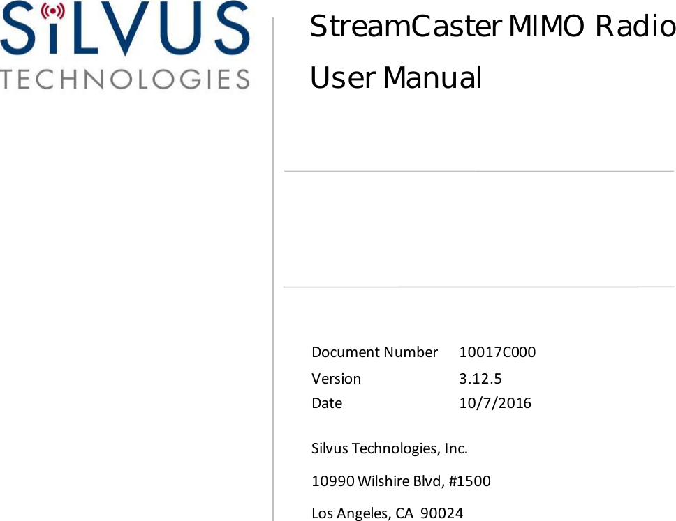

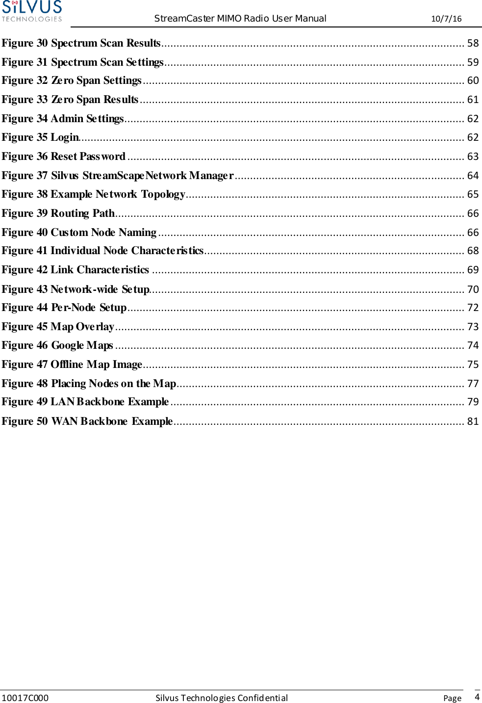


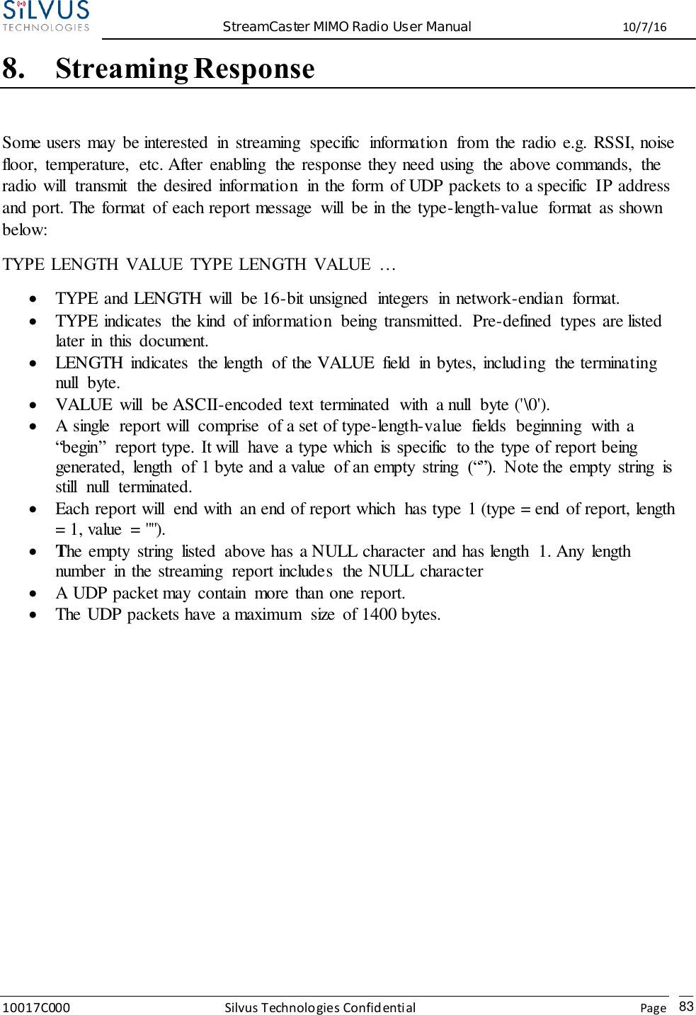
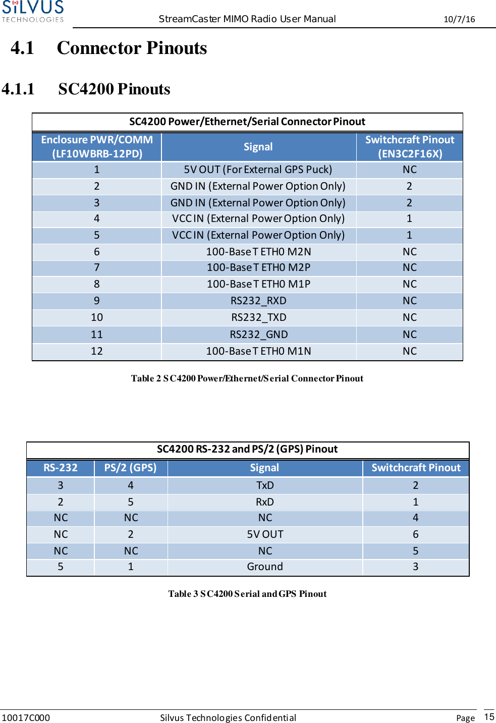
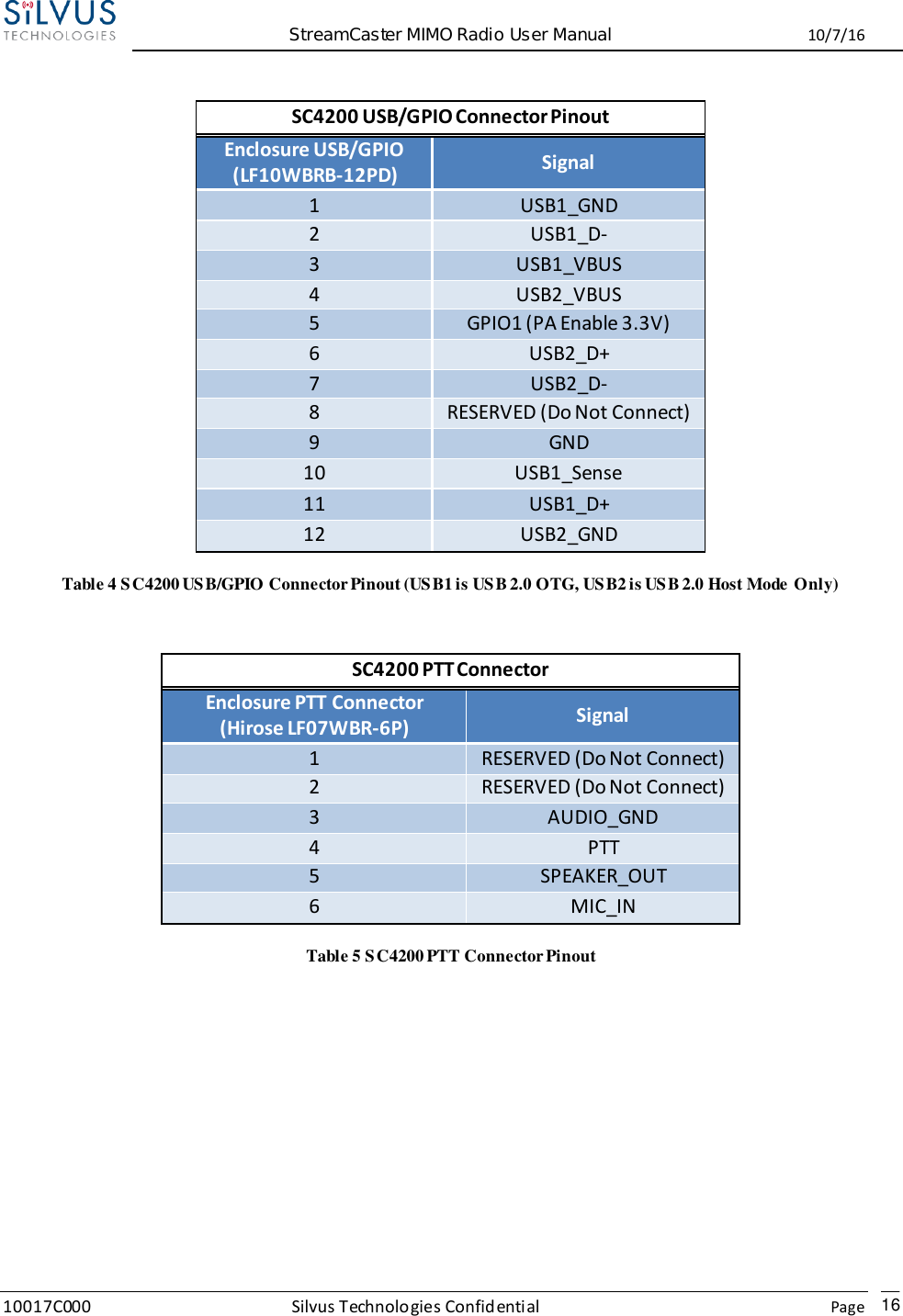
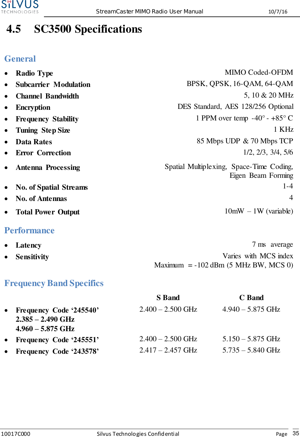
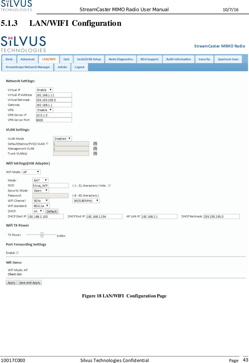
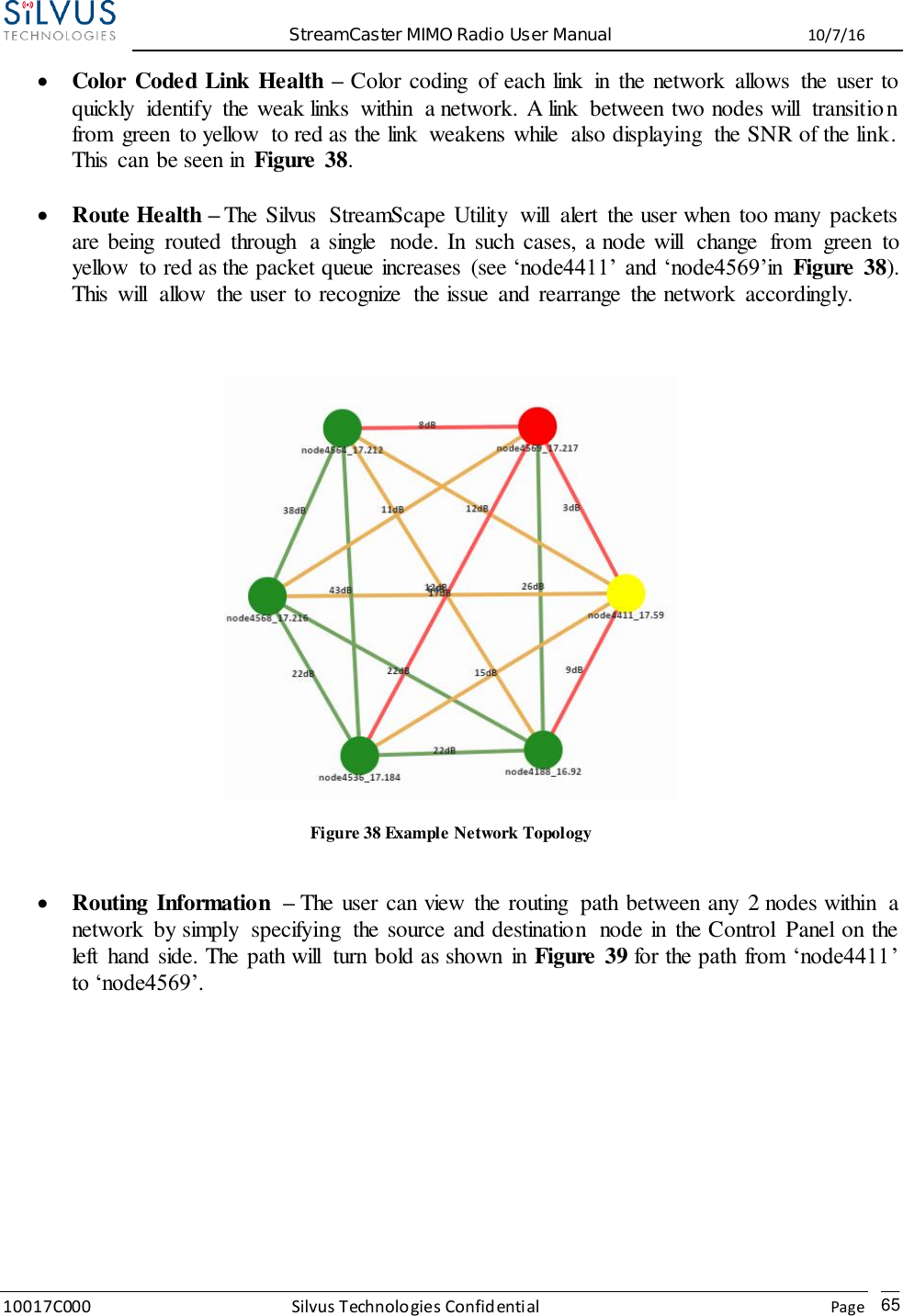
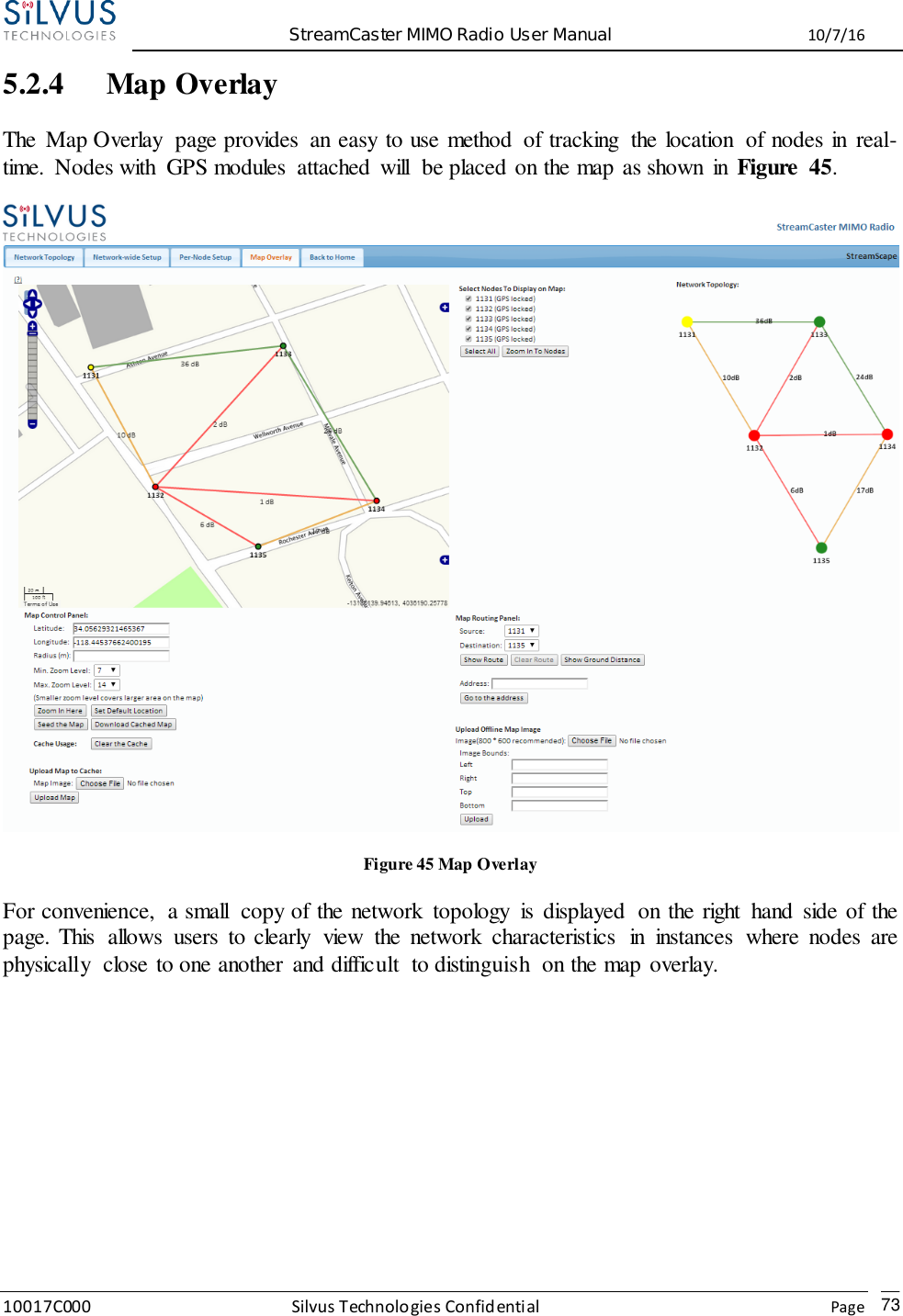
![StreamCaster MIMO Radio User Manual 10/7/16 10017C000 Silvus Technologies Confidential Page 10 4. StreamCaster Hardware Overview 4.1 Hardware Interfaces SC4200: Figure 1 StreamCaster 4200 Ruggedized Enclosure RF channels 1-2 connectors [TNC Female] Power Switch [2-Position Rotating] Power (Optional, 9-20V), Ethernet, and Serial Port connector [Hirose LF10WBRB-12PD] Bi-Color Status LED (See Section 11.1 for Troubleshooting Information) Red – Radio is in the process of booting up Flashing Green – Radio is fully booted but not wirelessly connected to any other radio Green – Radio is wirelessly connected to at least one other radio 1 2 3 4 1 3 5 4 6 2](https://usermanual.wiki/Silvus-Technologies/SC42-245/User-Guide-3166455-Page-12.png)
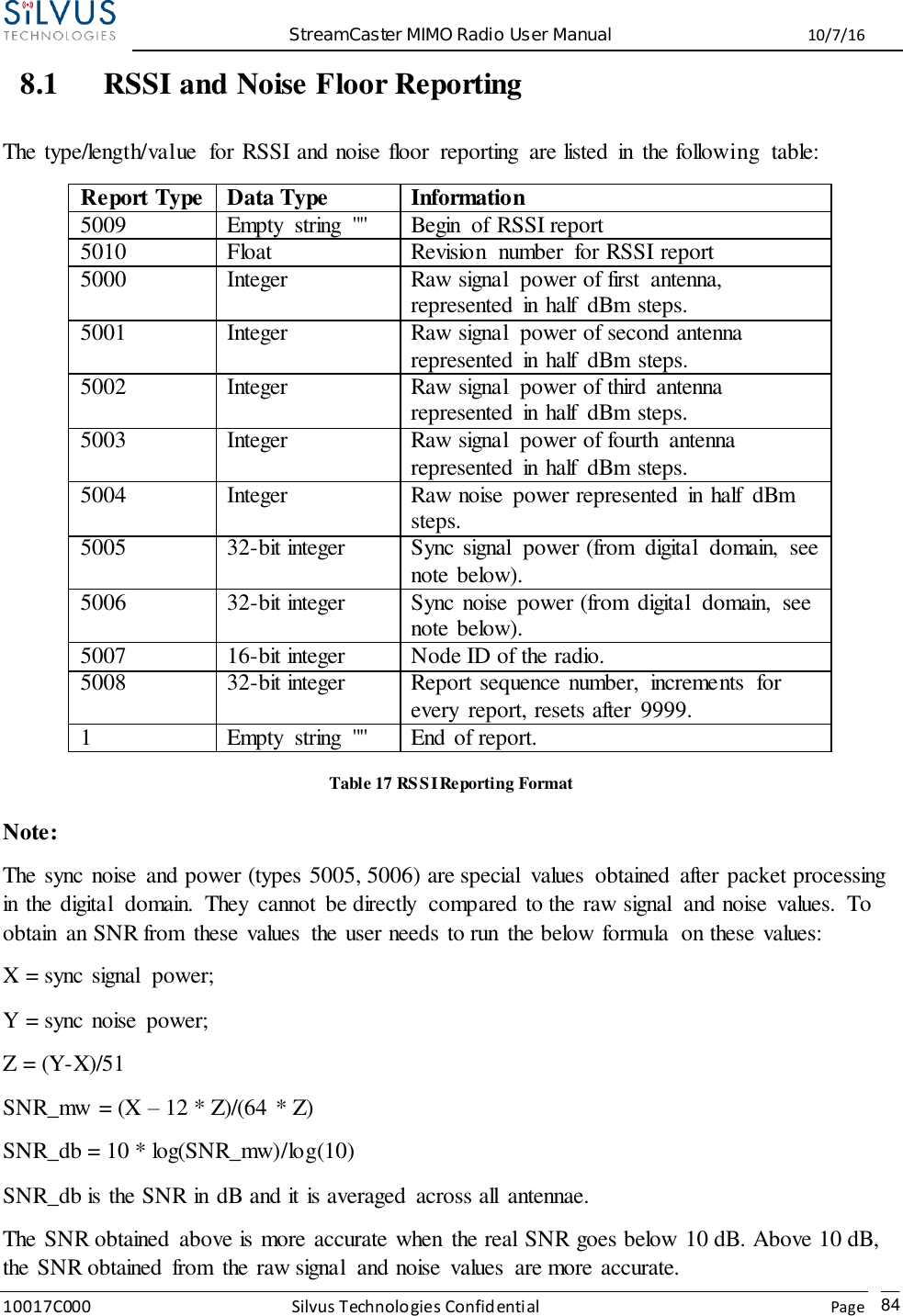
![StreamCaster MIMO Radio User Manual 10/7/16 10017C000 Silvus Technologies Confidential Page 11 Flashing Red – Radio has recovered from a bad state and has reverted to factory default settings. Push-to-Talk (PTT) Connector [Hirose LF07WBR-6P 12PD] USB/GPIO connector [Hirose LF10WBRB-12SD] 5 6](https://usermanual.wiki/Silvus-Technologies/SC42-245/User-Guide-3166455-Page-13.png)
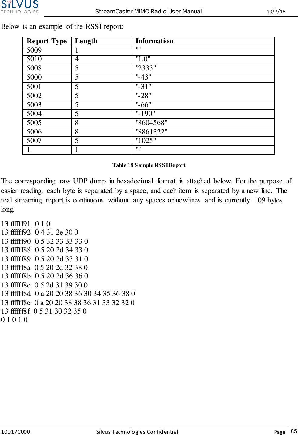
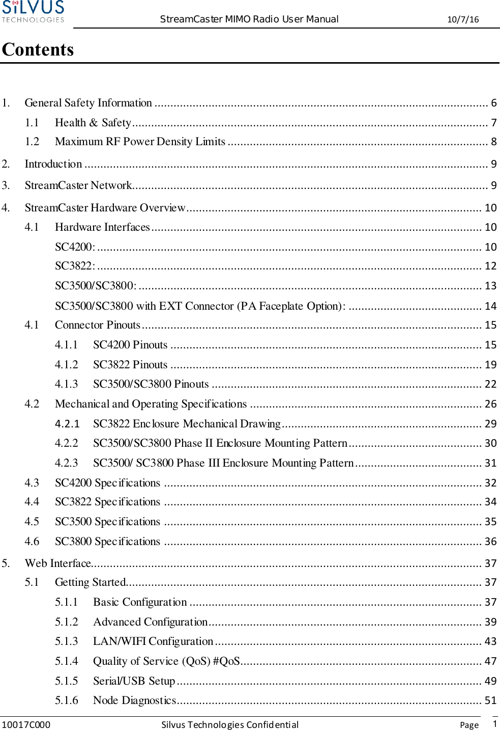
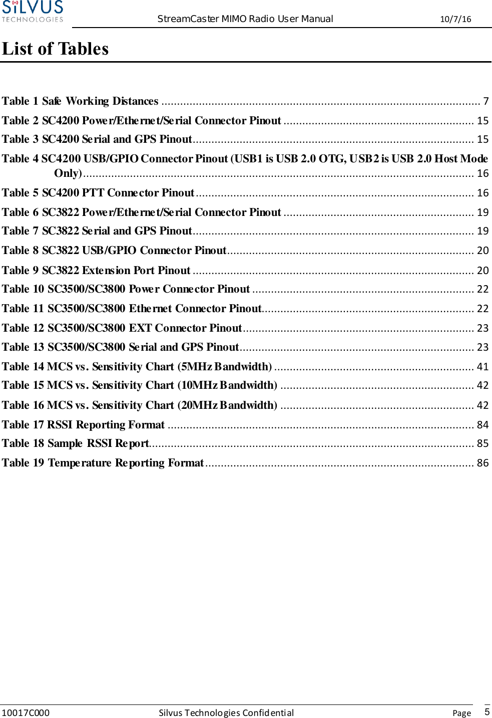
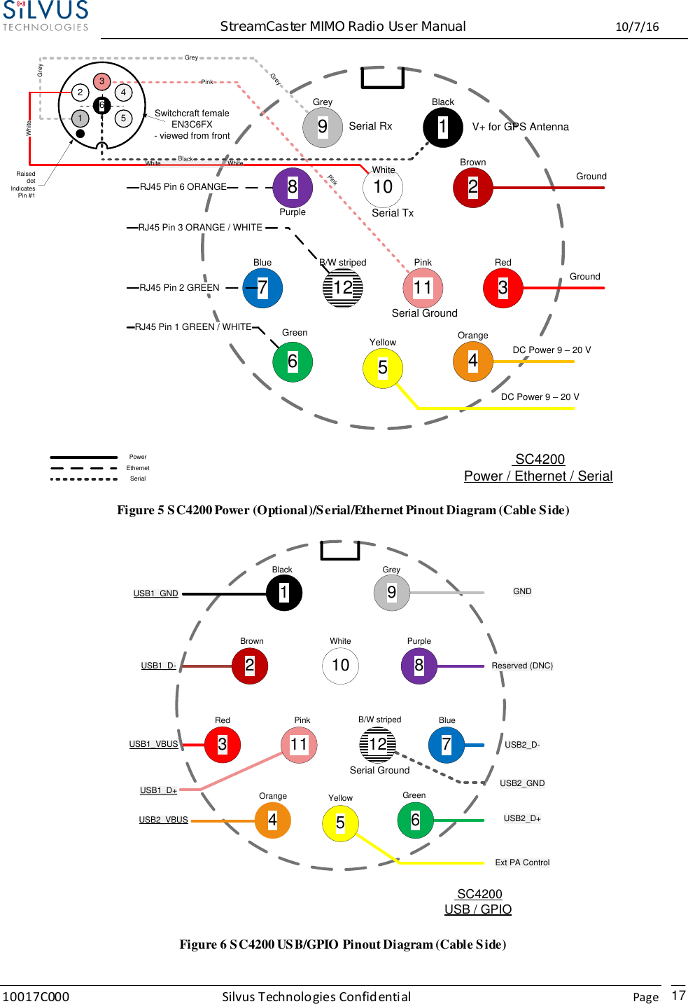
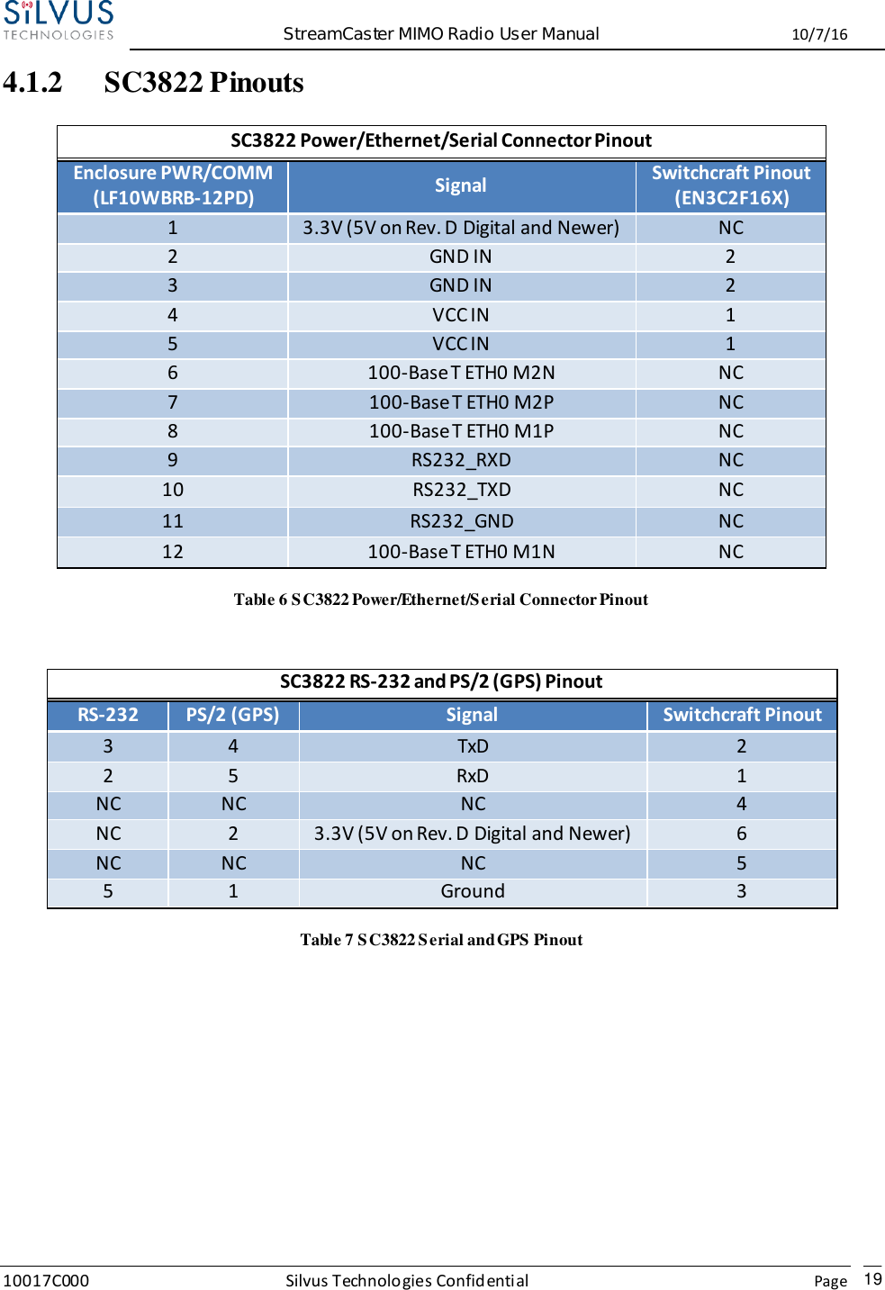
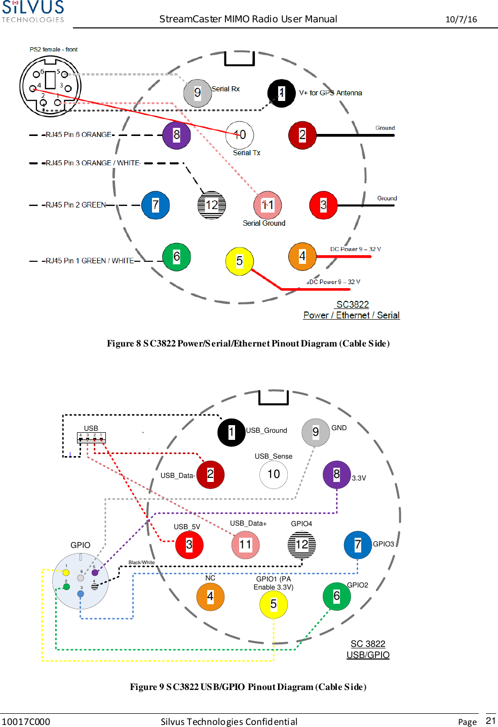
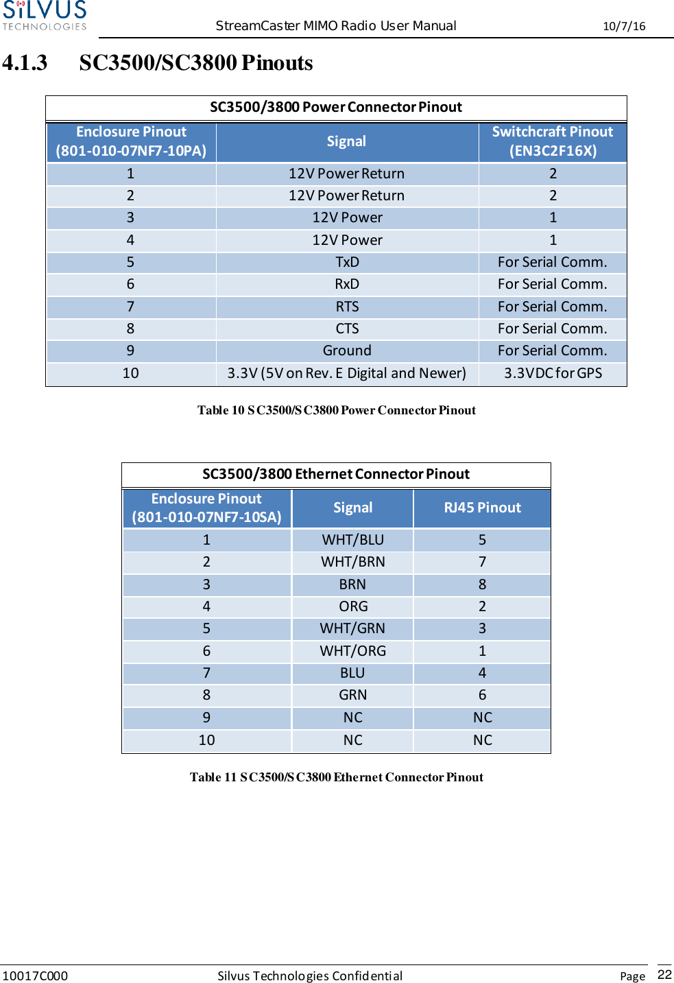
![StreamCaster MIMO Radio User Manual 10/7/16 10017C000 Silvus Technologies Confidential Page 12 SC3822: Figure 2 StreamCaster 3822 Ruggedized Enclosure RF channels 1-2 connectors [SMA Female] USB/GPIO connector [Hirose LF10WBRB-12SD] Tri-Color Status LED (See Section 11.1 for Troubleshooting Information) Red – Radio is in the process of booting up Orange – Radio is fully booted but not wirelessly connected to any other radio Green – Radio is wirelessly connected to at least one other radio Flashing Red – Radio has recovered from a bad state and has reverted to factory default settings. Power (9-32 VDC), Ethernet, and Serial Port connector [Hirose LF10WBRB-12PD] 1 2 3 4 2 1 3 4](https://usermanual.wiki/Silvus-Technologies/SC42-245/User-Guide-3166455-Page-14.png)
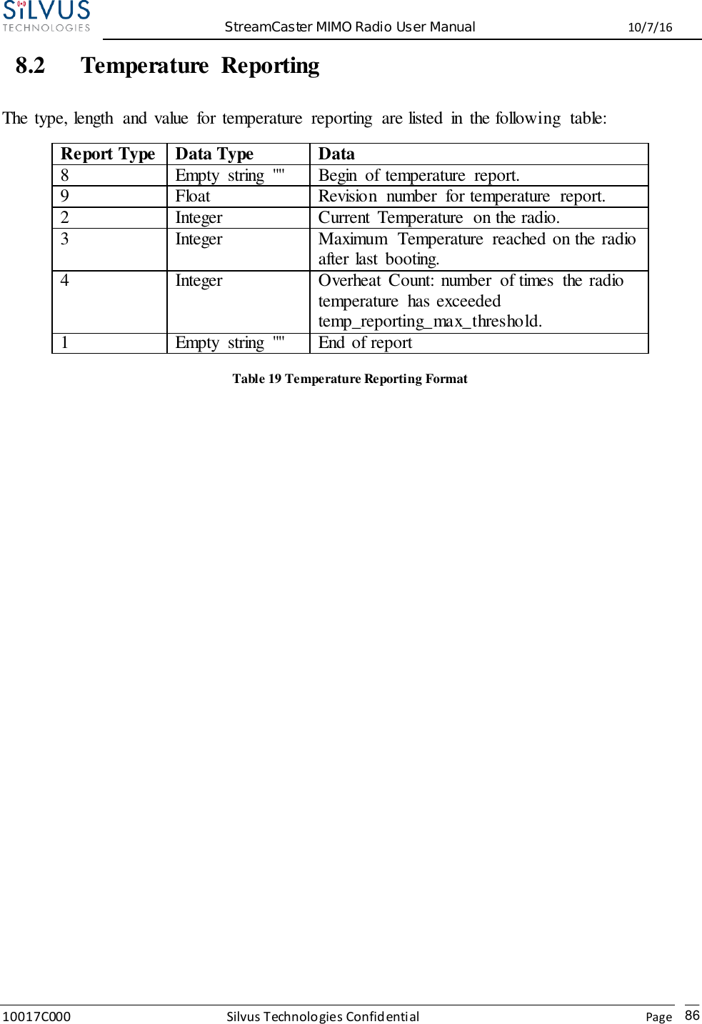
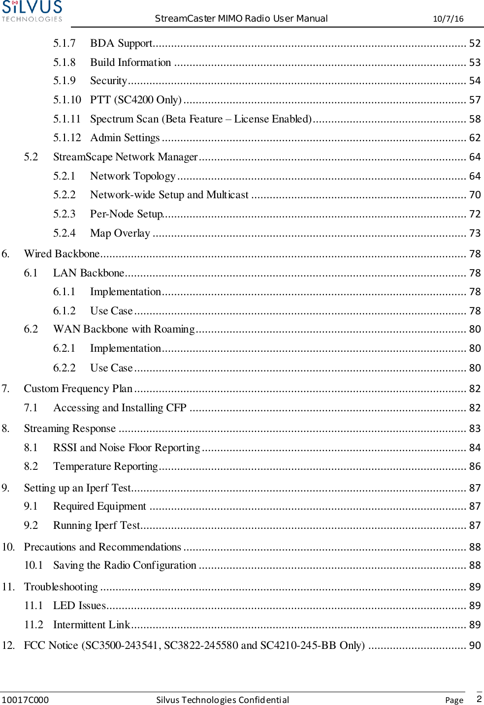
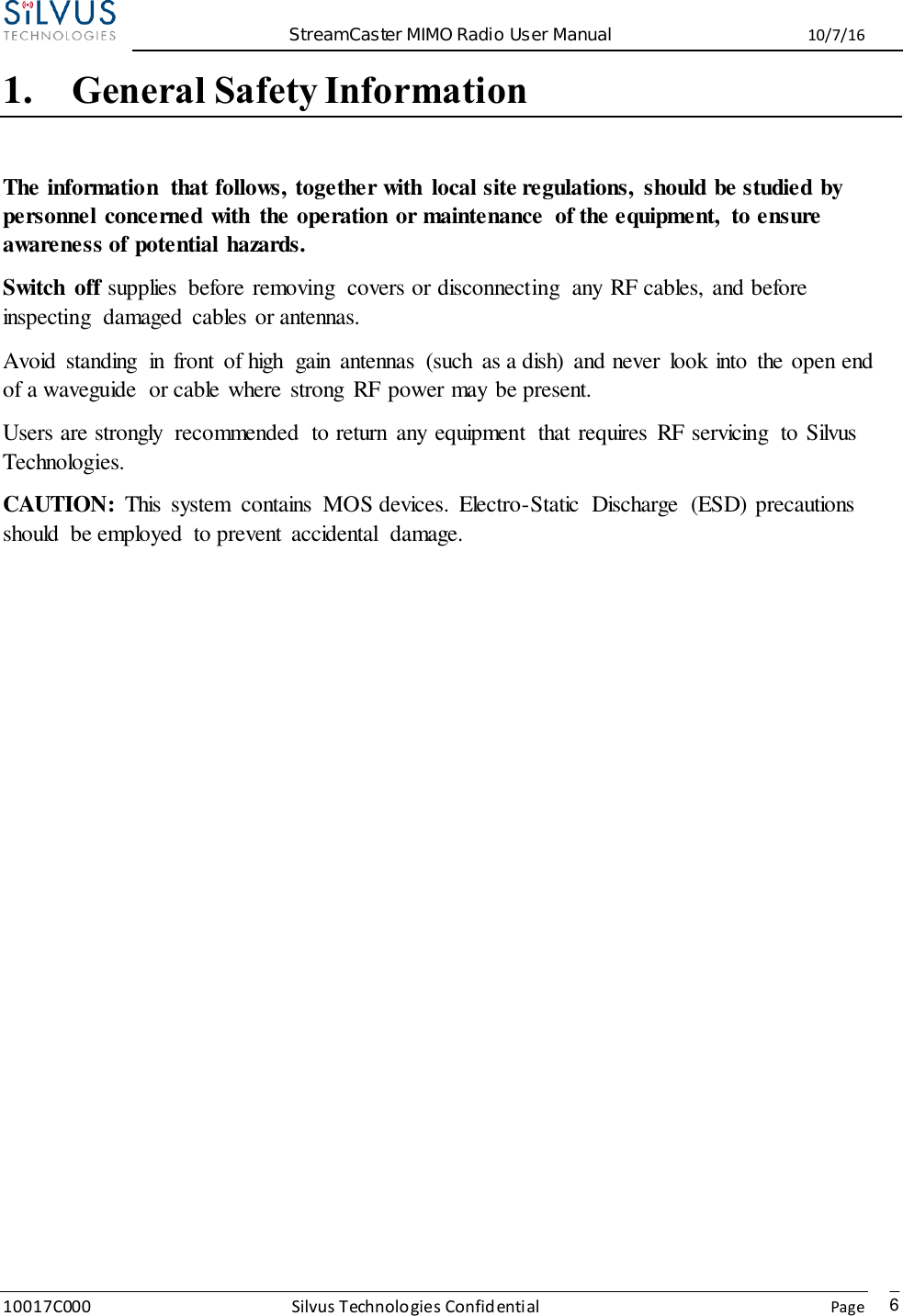
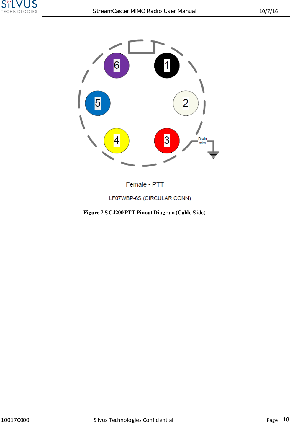
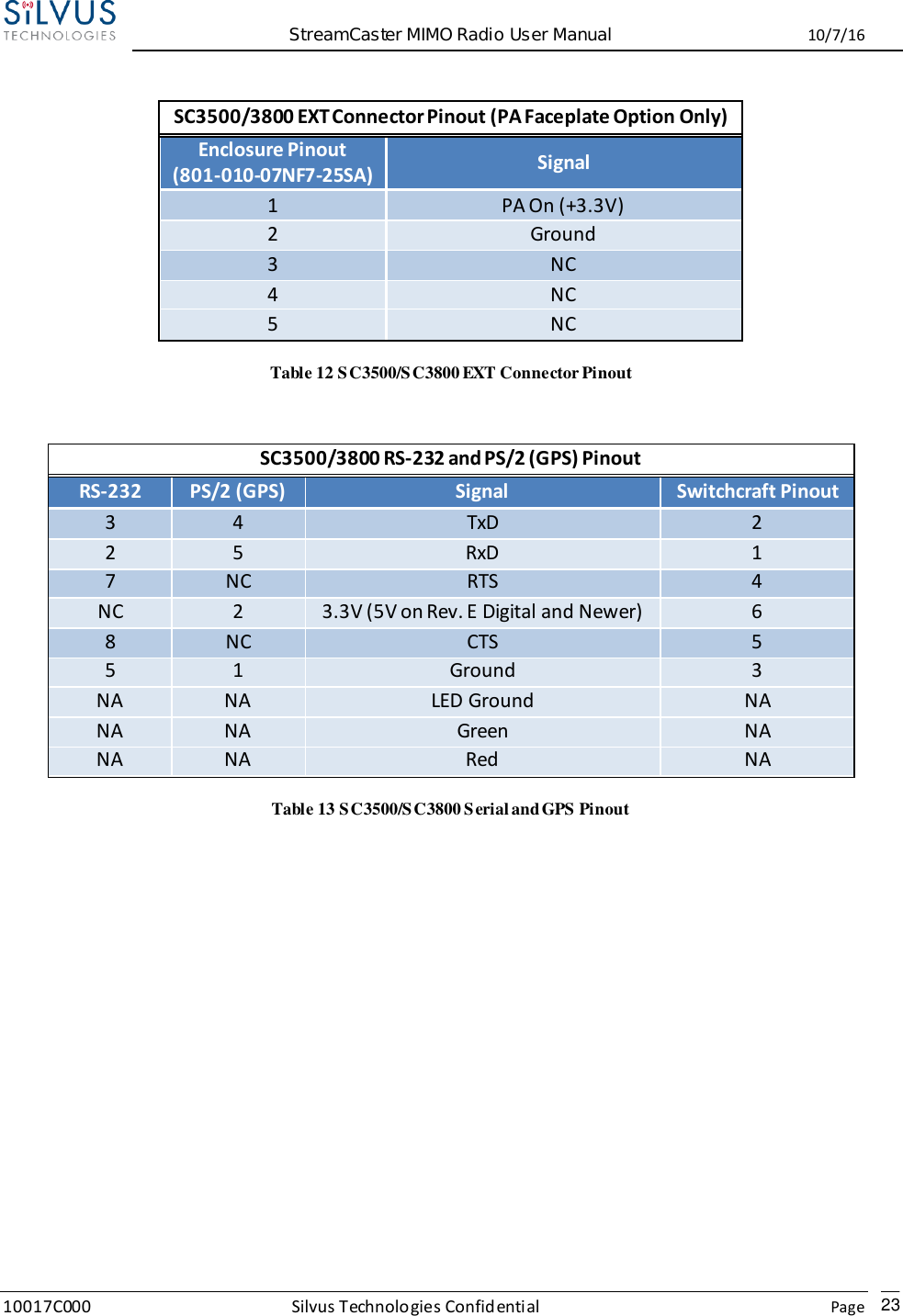
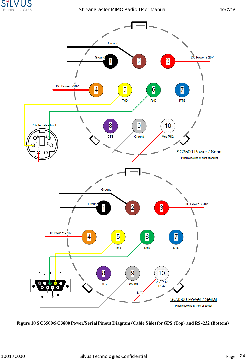
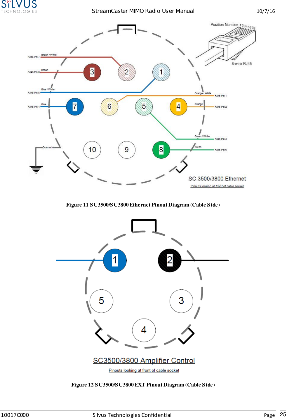
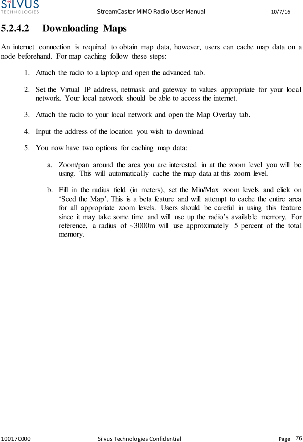
![StreamCaster MIMO Radio User Manual 10/7/16 10017C000 Silvus Technologies Confidential Page 13 SC3500/SC3800: Figure 3 StreamCaster 3500/3800 Ruggedized Enclosure RF channels 1-4 connectors [TNC Female] Ethernet connector [Mighty-Mouse 801-010-07NF7-10SA] Power (9-20 VDC) and Serial Port connector [Mighty-Mouse 801-010-07NF7-10PA] Tri-Color Status LED (See Section 11.1 for Troubleshooting Information) Red – Radio is in the process of booting up Orange – Radio is fully booted but not wirelessly connected to any other radio Green – Radio is wirelessly connected to at least one other radio Flashing Red – Radio has recovered from a bad state and has reverted to factory default settings Power Switch 1 2 3 4 5 2 3 4 5 1](https://usermanual.wiki/Silvus-Technologies/SC42-245/User-Guide-3166455-Page-15.png)
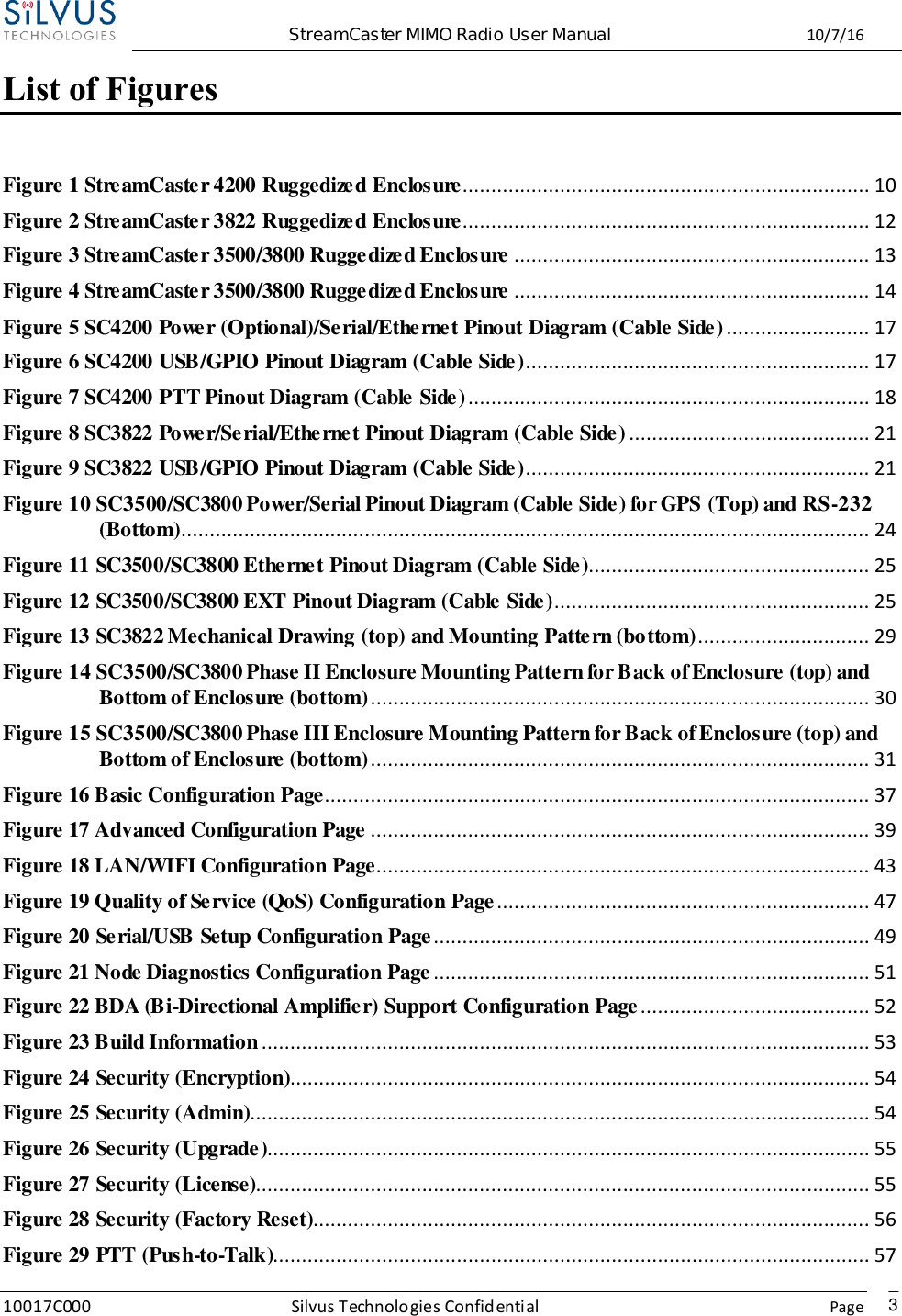
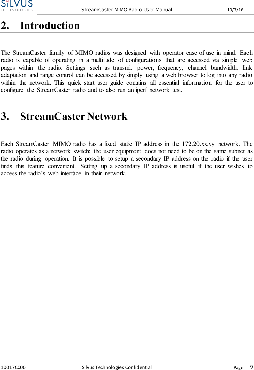
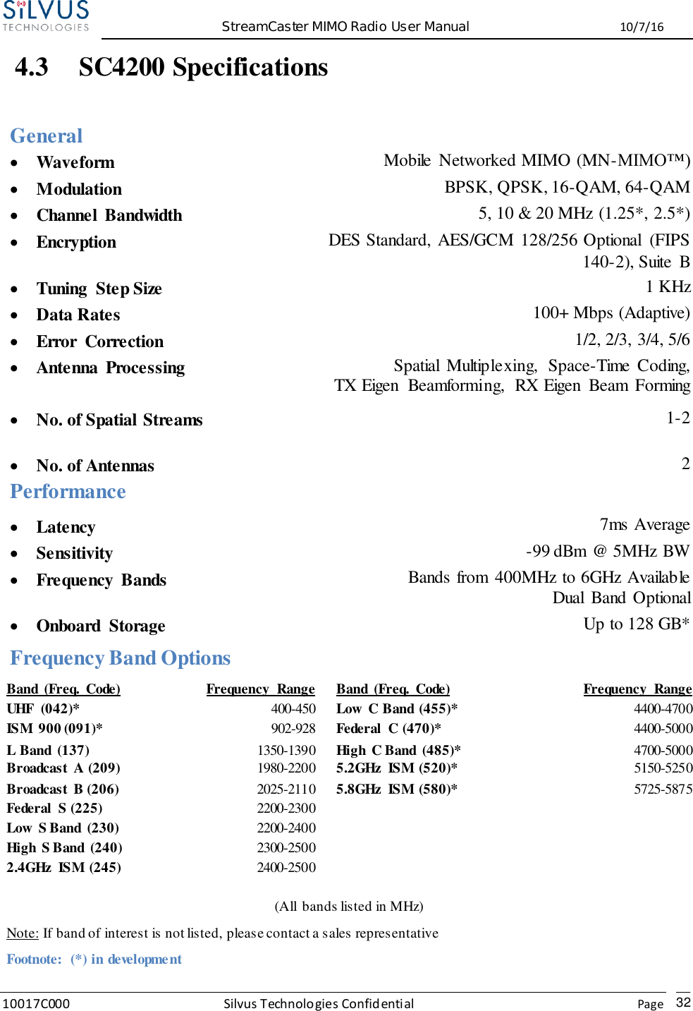
![StreamCaster MIMO Radio User Manual 10/7/16 10017C000 Silvus Technologies Confidential Page 14 SC3500/SC3800 with EXT Connector (PA Faceplate Option): Figure 4 StreamCaster 3500/3800 Ruggedized Enclosure RF channels 1-4 connectors [TNC Female] EXT PA Connector [Mighty-Mouse 801-010-07NF7-25SA] Ethernet connector [Mighty-Mouse 801-010-07NF7-10SA] Power (9-20 VDC) and Serial Port connector [Mighty-Mouse 801-010-07NF7-10PA] Power Switch Tri-Color Status LED (See Section 11.1 for Troubleshooting Information) Red – Radio is in the process of booting up Orange – Radio is fully booted but not wirelessly connected to any other radio Green – Radio is wirelessly connected to at least one other radio Flashing Red – Radio has recovered from a bad state and has reverted to factory default settings 1 2 3 4 5 6 2 3 4 1 6 5](https://usermanual.wiki/Silvus-Technologies/SC42-245/User-Guide-3166455-Page-16.png)


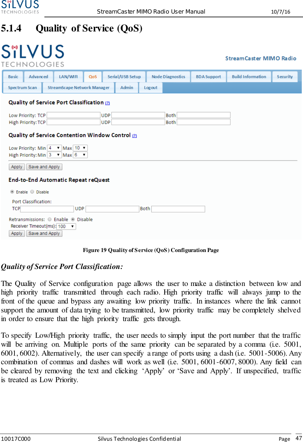
![StreamCaster MIMO Radio User Manual 10/7/16 10017C000 Silvus Technologies Confidential Page 48 Quality of Service Contention Window Control: The Quality of Service Contention Window Control tunes the aggressiveness of CSMA backoffs when collisions occur. The MAC takes random backoffs in the range [0, 2^cw_min]. Every time there is a collision/noise it will increase this cw_min by 1, until it is capped by cw_max. E.g. 4,10 translates to random backoffs in the range [0,16] in the beginning for a packet. If the first try results in a collision, it will pick another backoff in the range [0,32], then [0,64], until [0,1024]. After successful transmission, backoff is reset to [0,16]. The default is 4,10 for low priority, and 3,6 for high priority. For larger networks, it is recommended to increase the Low Priority minimum to reduce the chance of collisions occurring. End-to-End Automatic Repeat request (Beta Feature – License Enabled) The End-to-End ARQ feature provides packet re-ordering capability to the radio. This feature is useful in applications that are sensitive to out of order packets (i.e. video applications where the decoder does not have the ability to re-order packets). To enable packet reordering, specify the port number of the subject data in the same format as the QoS ports on the source and destination radio. The settings should match on both radios and do not need to be set on any relays. Retransmissions Disabled – Only packet re-ordering with no end-to-end retransmissions if packets are lost. The receiver timeout is the length of time the receiver waits for out-of-order packets before giving up and delivering the data it has in its buffer. This is similar in concept to the jitter buffer in common video decoders (e.g. VLC). The worst case end-to-end delay will be incremented by the receiver timeout value. Retransmissions Enabled – Packet re-ordering and end-to-end retransmissions enabled in case of packet loss. The retransmission timeout is the time the transmitter will wait before re-sending a lost packet. The worst case end-to-end delay will be incremented by the retransmission timeout value. Determining Timeout Value – Both receiver timeout and retransmission timeout should be set to roughly 3 times the end-to-end latency. The end-to-end latency can be found by disabling e2e and doing a ping between the transmitter and receiver.](https://usermanual.wiki/Silvus-Technologies/SC42-245/User-Guide-3166455-Page-50.png)


![StreamCaster MIMO Radio User Manual 10/7/16 10017C000 Silvus Technologies Confidential Page 82 7. Custom Frequency Plan 7.1 Accessing and Installing CFP The hidden Custom Frequency Plan page can be accessed via http://<radio IP>/custom_freq.sh The interface will allow an upload of a custom frequency plan file which should be in the following format: { "type": "custom_frequency_plan", "name": "cfp_example", "description": "CFP Example", "frequencies": [ "2412", "2417", "2422", "2427", "2432", "2437", "2442", "2447", "2452", "2457", "2462", "2467", "2472", "5745", "5765", "5785", "5805", "5825" ] } (Put the above format in a Text file. Name/description can be changed) Custom Frequency Plan Text file example: https://drive.google.com/file/d/0ByThlCSjgHe1TDMtZ2xDXzhEblE/view?usp=sharing The numbers can be changed to the frequencies desired. The name of the text file does not matter in order to be utilized. After uploading the file, the web interface will be populated with the Custom Frequency Plan. Note: Once installed, the Custom Frequency Plan will be cross-checked with hardware capability and the licensed frequency range previously installed on the radio. The Custom Frequency Plan will only change what is displayed. It will not give new frequencies that are previously out of licensed range.](https://usermanual.wiki/Silvus-Technologies/SC42-245/User-Guide-3166455-Page-84.png)