Simcom 0606020080117 GSM/GPRS Module User Manual
Shanghai Simcom Ltd. GSM/GPRS Module Users Manual
Simcom >
Users Manual
Development Kit Manual
SIM345-EVB_UGD_V1.02
SIM345 EVB User Guide
SIM345-EVB_UGD_V1.02 15.02.2008
2
Document Title: SIM345 EVB User Guide
Version: 1.02
Date: 2008-2-15
Status: Release
Document Control ID: SIM345-EVB_UGD_V1.02
General Notes
SIMCom offers this information as a service to its customers, to support application and
engineering efforts that use the products designed by SIMCom. The information provided is
based upon requirements specifically provided to SIMCom by the customers. SIMCom has
not undertaken any independent search for additional relevant information, including any
information that may be in the customer’s possession. Furthermore, system validation of this
product designed by SIMCom within a larger electronic system remains the responsibility of
the customer or the customer’s system integrator. All specifications supplied herein are
subject to change.
Copyright
This document contains proprietary technical information which is the property of SIMCom
Limited., copying of this document and giving it to others and the using or communication of
the contents thereof, are forbidden without express authority. Offenders are liable to the
payment of damages. All rights reserved in the event of grant of a patent or the registration of
a utility model or design. All specification supplied herein are subject to change without
notice at any time.
FCC Caution:
To assure continued compliance, any changes or modifications not expressly approved by the
party responsible for compliance could void the user's authority to operate this equipment.
(Example - use only shielded interface cables when connecting to computer or peripheral
devices).
This device complies with Part 15 of the FCC Rules. Operation is subject to the following two
conditions:
(1) This device may not cause harmful interference;
(2) This device must accept any interference received, including interference that may cause
undesired operation.
Copyright © SIMCom Limited. 2008

SIM345 EVB User Guide
SIM345-EVB_UGD_V1.02 15.02.2008
3
Contents
Contents ............................................................................................................................................3
1 SIM345 EVB .................................................................................................................................5
2 EVB accessory ...............................................................................................................................7
3 Accessory Interface........................................................................................................................8
3.1 Power Interface ....................................................................................................................8
3.2 Audio Interface.....................................................................................................................8
3.3 SIM card interface................................................................................................................9
3.4 Antenna Interface ...............................................................................................................10
3.5 RS232 Interface..................................................................................................................11
3.6 Operating Status LED ........................................................................................................12
4 Test Interface................................................................................................................................13
4.1 Serial Interface ...................................................................................................................13
4.2 J102---KEY & POWER .....................................................................................................14
4.3 J103---GPIO.......................................................................................................................15
5 EVB and accessory equipment.....................................................................................................16
6 Illustration ....................................................................................................................................17
6.1 Running..............................................................................................................................17
6.2 Connecting Net and calling................................................................................................17
6.3 Downloading......................................................................................................................17
6.4 Turns off.............................................................................................................................17
Figure Index
FIGURE 1: EVB TOP VIEW...................................................................................................................5
FIGURE 2: EVB BOTTOM VIEW..........................................................................................................6
FIGURE 3: EVB ACCESSORY...............................................................................................................7
FIGURE 4: POWER INTERFACE..........................................................................................................8
FIGURE 5: AUDIO INTERFACE ...........................................................................................................8
FIGURE 6: SIM CARD INTERFACE.....................................................................................................9
FIGURE 7: ANTENNA INTERFACE ...................................................................................................10
FIGURE 8: UART1 SERIAL PORT AND UART4 SERIAL PORT...................................................... 11
FIGURE 9: UART2 SERIAL PORT ...................................................................................................... 11
FIGURE 10: FLASH LED .....................................................................................................................12
FIGURE 11: TEST INTERFACE OVERVIEW.....................................................................................13
FIGURE 12: J1 INTERFACE ................................................................................................................13
FIGURE 13: J102 INTERFACE ............................................................................................................14
FIGURE 14: J3 INTERFACE ................................................................................................................15
FIGURE 15: EVB AND ACCESSORY EQUIPMENT .........................................................................16

SIM345 EVB User Guide
SIM345-EVB_UGD_V1.02 15.02.2008
4
SCOPE
This document give the usage of SIM345 EVB, user can get useful info about the SIM345 EVB
quickly through this document.
The SIM345 only supports 850MHz/1900MHz functions.
This document is subject to change without notice at any time.
SIM345 EVB User Guide
SIM345-EVB_UGD_V1.02 15.02.2008
5
1 SIM345 EVB
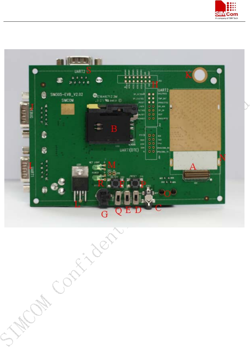
Figure 1: EVB TOP view
SIM345 EVB User Guide
SIM345-EVB_UGD_V1.02 15.02.2008
6
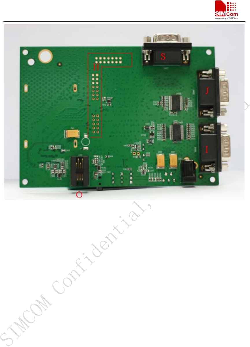
Figure 2: EVB BOTTOM view
A: SIM345 module interface
B: SIM card interface
C: Headset interface
D: Charge switch, switch on or off charging function
E: Download switch, turn on or off download function
F: ON/OFF key, turn on or turn off SIM345
G: Buzzer
H: Expand port, such as keypad port, main serial port, SPI port
I: Main serial port UART1 for downloading, AT command transmitting, data exchanging
J: General Purpose output or input ports for customers’ application, but can be multiplexed
with another auxiliary serial port for internal ONLY
K: Hole for fixing the antenna
L: Source adapter interface
M: FLASH LED light
N: Hole for fixing the SIM345
O: Headphones interface
P: Reset key, reset module for exigency
Q: VBATT switch, switch the voltage source from the adaptor or external battery
S: Auxiliary serial port UART2
SIM345 EVB User Guide
SIM345-EVB_UGD_V1.02 15.02.2008
7
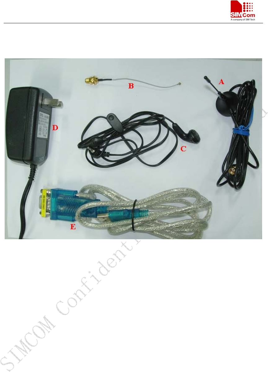
2 EVB accessory
Figure 3: EVB accessory
A: Antenna
B: Antenna transmit line
C: Headset
D: 5V DC source adapter
E: USB to serial port line
SIM345 EVB User Guide
SIM345-EVB_UGD_V1.02 15.02.2008
8
3 Accessory Interface
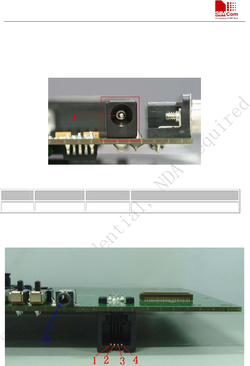
3.1 Power Interface
Figure 4: Power Interface
Pin Signal I/O Description
1 Adapter input I 5V/2.5A DC source input
3.2 Audio Interface
Figure 5: Audio Interface
SIM345 EVB User Guide
SIM345-EVB_UGD_V1.02 15.02.2008
9
Headset interface:
Pin Signal I/O Description
1 MIC2P I Positive microphone input
2 SPK2P O Positive speak output
3 SPK2N O Negative speak output
4 MIC2N I Negative microphone input
Earphone interface:
Pin Signal Input/Output Description
5 MIC1P&SPK1P I/O Auxiliary positive input and output
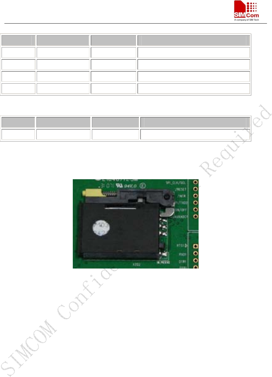
3.3 SIM card interface
Figure 6: SIM card interface
SIM345 EVB User Guide
SIM345-EVB_UGD_V1.02 15.02.2008
10
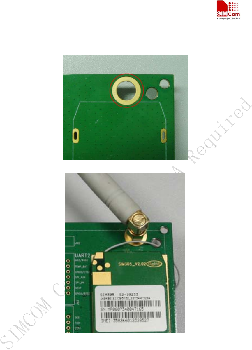
3.4 Antenna Interface
Figure 7: Antenna Interface
SIM345 EVB User Guide
SIM345-EVB_UGD_V1.02 15.02.2008
11
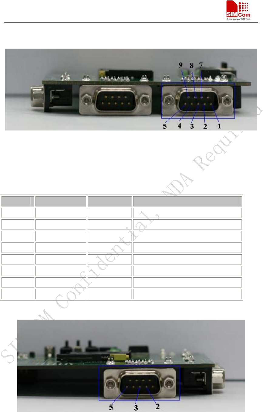
3.5 RS232 Interface
Figure 8: UART1 Serial Port
Main port UART1——A full functional seven-wires serial port
Auxiliary serial port UART2——An auxiliary three-wires serial interface
Main serial port(UART1):
Pin Signal I/O Description
1 DCD O Data carrier detection
2 TXD1 O Transmit data
3 RXD1 I Receive data
4 DTR I Data Terminal Ready
5 GND GND
7 RTS I Request to Send
8 CTS O Clear to Send
9 RI O Ring Indicator
Figure 9: UART2 Serial Port
SIM345 EVB User Guide
SIM345-EVB_UGD_V1.02 15.02.2008
12
Auxiliary serial port (UART2):
Pin Signal I/O Description
2 RXD2 O Receive data
3 TXD2 I Transmit data
5 GND GND
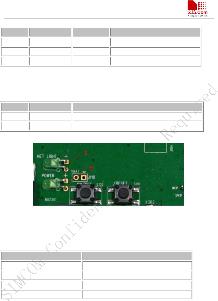
3.6 Operating Status LED
Pin Signal Description
1 Flash LED
Network status indication LED
2 Power light
VBATT power supply status indication
Figure 10: Flash LED
Working state of Flash LED as list:
State Module function
Off Module is not running
Permanent on Module does not find the network
60ms On/ 3000ms +50%Off Module find the network
60ms On/ 852ms +50% Off GPRS communication
SIM345 EVB User Guide
SIM345-EVB_UGD_V1.02 15.02.2008
13
4 Test Interface
Figure 11: Test interface overview
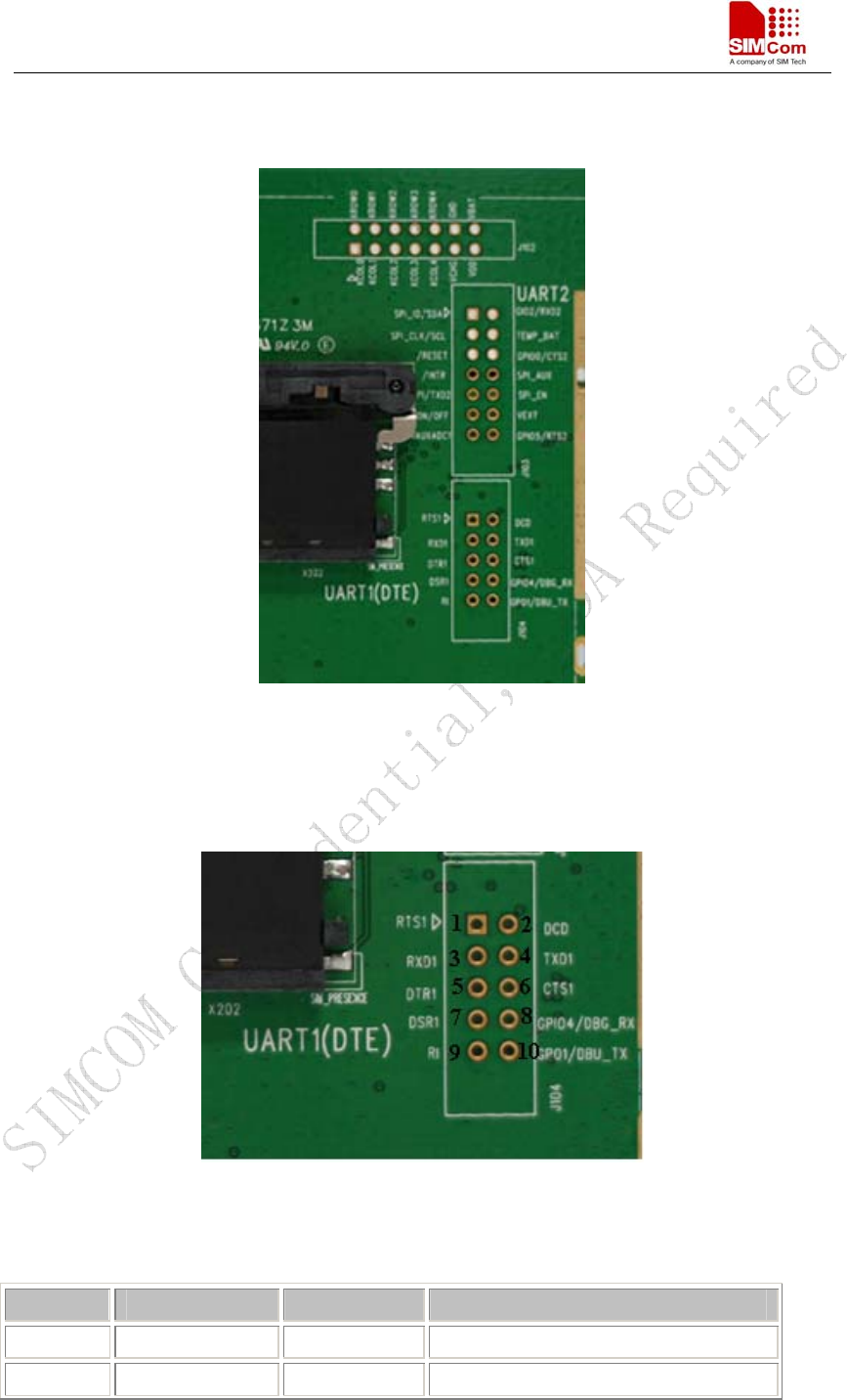
4.1 Serial Interface
J104—UART1 serial port
Figure 12: J1 Interface
RS232 Interface Pin List:
Pin Signal I/O Description
1 RTS I Request to Send
2 DCD O Data carrier detection
SIM345 EVB User Guide
SIM345-EVB_UGD_V1.02 15.02.2008
14
3 RXD1 O Receive data
4 TXD1 I Transmit data
5 DTR I Data Terminal Ready
6 CTS O Clear to Send
7 DSR I
8 GPIO4 I/O Transmit or receive data
9 RI O Ring Indicator
10 GPO1 O Transmit data
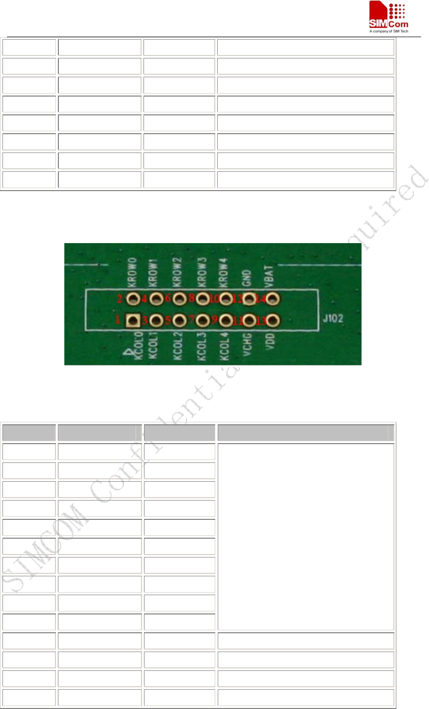
4.2 J102---KEY & POWER
Figure 13: J102 Interface
KEY & POWER Pin List
Pin Signal I/O Description
1 COL0 O
2 ROW0 I
3 COL1 O
4 ROW1 I
5 COL 2 O
6 ROW2 I
7 COL 3 O
8 ROW3 I
9 COL 4 O
10 ROW4 I
Keypad array interface
11 CHG_IN
12 GND I
13 VDD
14 VBATT I
SIM345 EVB User Guide
SIM345-EVB_UGD_V1.02 15.02.2008
15
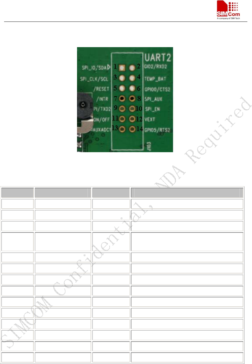
4.3 J103---GPIO
Figure 14: J3 Interface
SPI & I/O Interface Pin List:
Pin Signal I/O Description
1 SPI_IO/ SDA I/O IIC interface
2 GPO2 O General Purpose Output Port
3 SPI_CLK/ SCL O IIC interface
4 TEMP_BAT I ADC input for battery temperature
measurement
5 /RST I Reset module for emergency
6 GPIO0 I/O General Purpose Input/Output Port
7 /INTR I External interrupt input
8 GPO0 / SPI_AUX O General Purpose Output Port
9 GPI I General Purpose Input
10 SPI_EN/ GPO3 O General Purpose Output Port
11 ON/OFF I To switch on or off the module
12 VCC O Output digital power supply
13 AUXV0 I Auxiliary ADC input
14 GPIO5 I/O General Purpose Input/Output Port
SIM345 EVB User Guide
SIM345-EVB_UGD_V1.02 15.02.2008
16
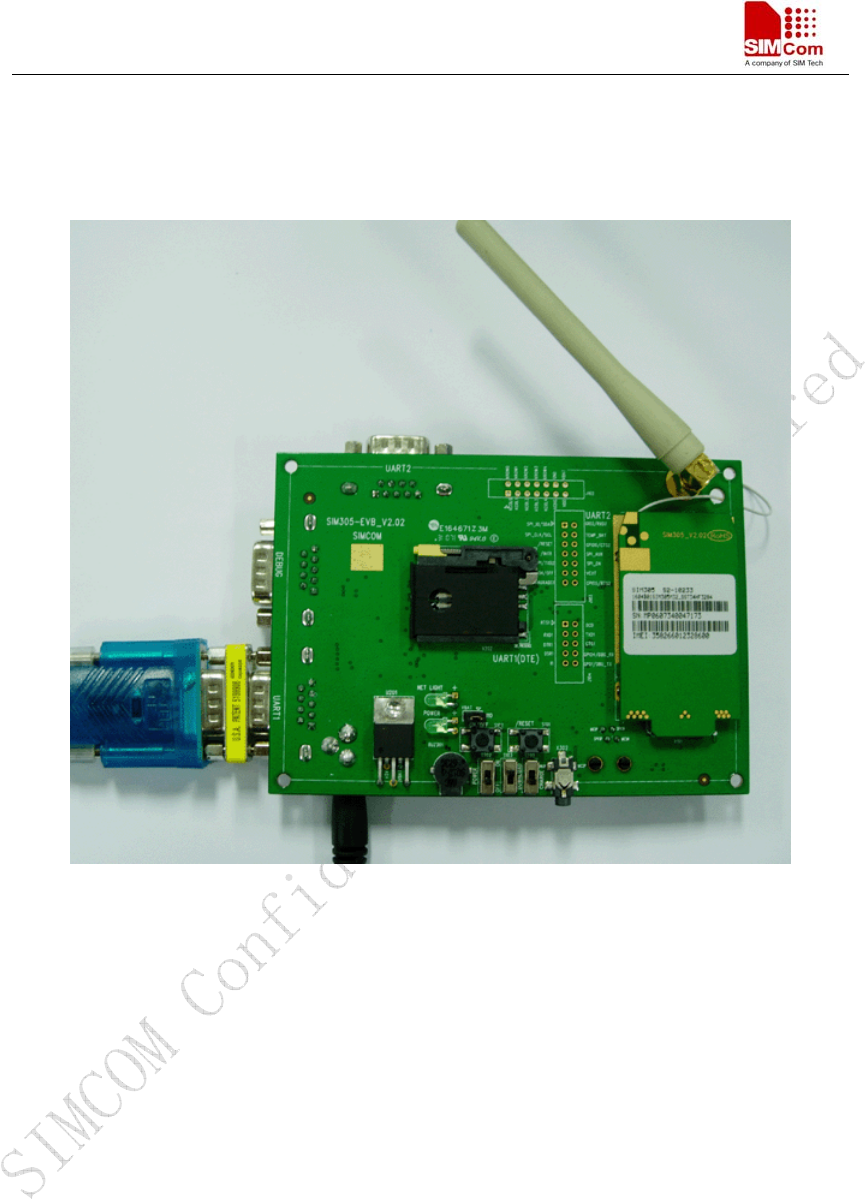
5 EVB and accessory equipment
At normal circumstance, the EVB and its accessory are equipped as the Figure 15
Figure 15: EVB and accessory equipment

SIM345 EVB User Guide
SIM345-EVB_UGD_V1.02 15.02.2008
17
6 Illustration
6.1 Running
(1) Connect the SIM345 module to the 60 pins connector on SIM345 EVB, inserting 5V direct
current source adapter, switching the S103 switch on off state, S202 switch on ON state;
(2) Press the ON/OFF for about 2 second, and then SIM345 module begins running.
You can see the light on the EVB flashing at a certain frequency. By the state, you can judge
whether the EVB and SIM345 can run or not. No function and test can be executed when we have
not connected necessary accessories.
6.2 Connecting Net and calling
(1) Connect the serial port line to the MAIN serial port, open the HyperTerminal (AT command
windows) on your Personal computer, the location of the HyperTerminal in windows2000 is
START→accessory→communication→HyperTerminal. Set correct Baud Rate and COM number.
The Baud Rate of SIM345 is 115200, and the COM number based on which USB port your serial
port line insert in, you should select such as COM3 or COM4 etc.
(2) Connect the antenna to the SIM345 module using an antenna transmit line, insert SIM card
into the SIM card interface, and insert headphones or headset into its interface.
(3) Act on the step of running which mentioned above, power on the system, typing the AT
command in the HyperTerminal, and then the SIM345 module will execute its corresponding
function.
6.3 Downloading
Connect the serial port line to the MAIN serial port, connect the direct current source adapter, run
the download program and press the START key, then switch the POWER switch on ON state,
DOWNLOAD switch on ON state, and then EVB provide the function of downloading.
6.4 Turns off
Turn off SIM345 module: press the ON/OFF for about 2 second, SIM345 module will be turned
off.
●RF exposure requirements
To allow compliance with RF exposure requirements,the SIM345’s maximum output
power is 33dBm in GSM850/GSM900 band,or 30dBm in DCS1800/PCS1900 band,
and the maximum antenna gain is 3dBi,and the minimum cable loss is 0.5db.
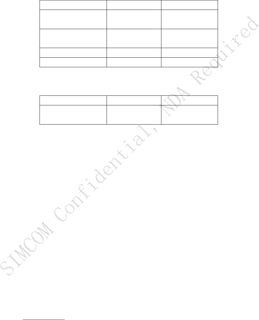
●The Antenna Parameter of SIM345
GSM850/GSM900 DCS1800/PCS1900
VSWR(Max.)Operation
band
≤2.5 ≤2.5
VSWR(Min.)Outside the
operation band
≥3 ≥3
GAIN(Min)(dBi) >0dBi > 1dBi
Output Power (dBm) >30dBm >27dBm
●The Module’s Conducted Reception Characteristic
GSM850/GSM900 DCS1800/PCS1900
Conducted RX Level
@BER<2%(dBm)
-106 -106
●IMPORTANT NOTE:
FCC Radiation Exposure Statement:
This equipment complies with FCC radiation exposure limits set forth for an
uncontrolled environment. This equipment should be installed and operated with a
minimum distance of about eight inches (20cm) between the radiator and your body.
Contact us:
Shanghai SIMCom Ltd.
Add: SIM Technology Building, No. 700, Yishan Road, Shanghai,P. R. China 200233
Tel: +86 21 5427 8900
Fax: +86 21 5427 6035
URL: www.sim.com