Simcom 2013060302 GSM/GPRS/EDGE/UMTS/HSDPA Terminal User Manual unser manual
Shanghai Simcom Ltd. GSM/GPRS/EDGE/UMTS/HSDPA Terminal unser manual
UserManual.wiki
>
Simcom
>
2013060302 User Manual
>
unser manual
Contents
1.
unser manual
2.
usermanual
unser manual
Navigation menu
Upload a User Manual
Namespaces
Wiki Guide
HTML
PDF
Info
Views
User Manual
Discussion / Help
Navigation
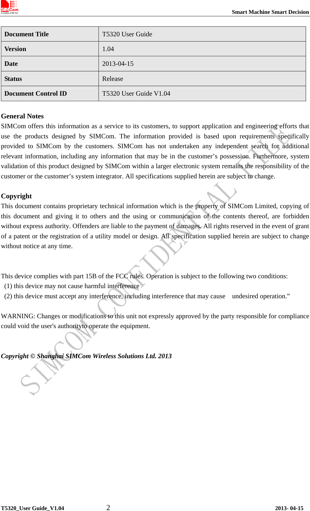
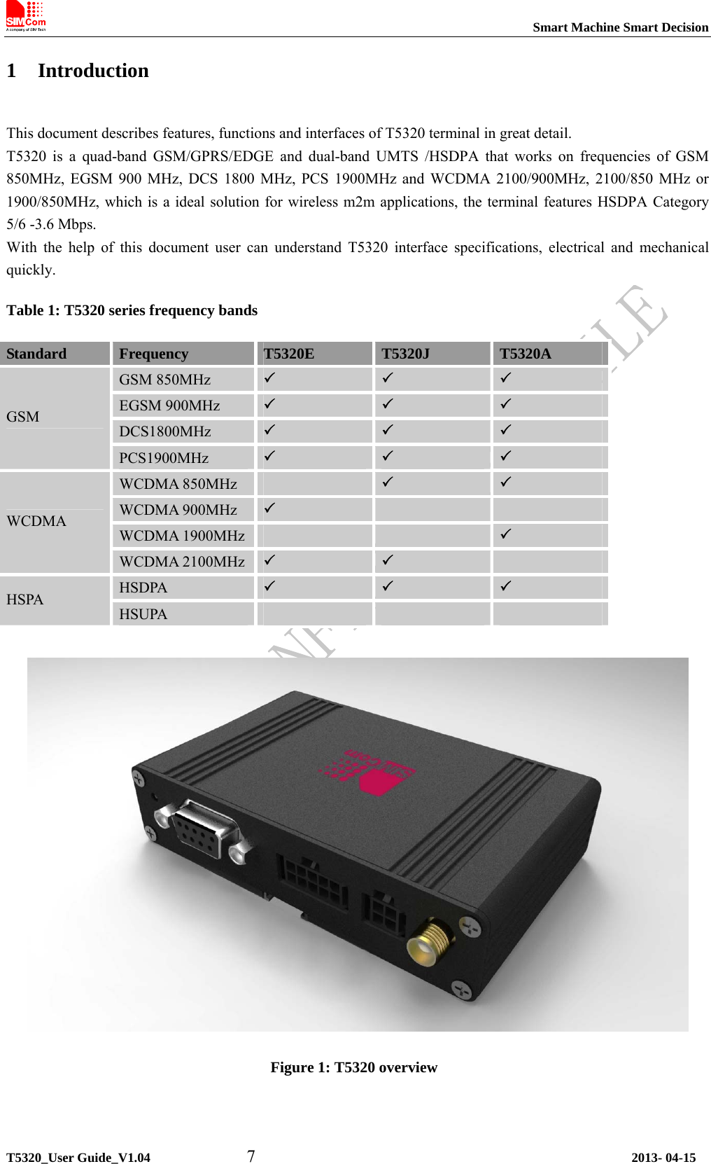
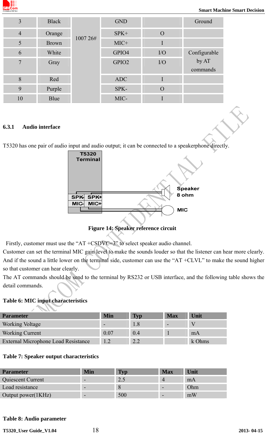
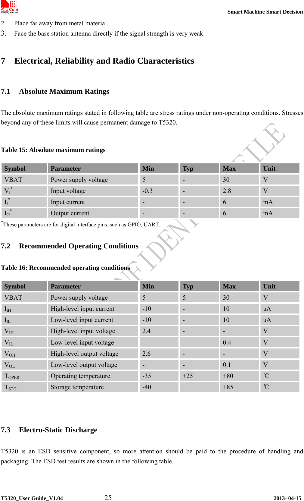
![Smart Machine Smart Decision T5320_User Guide_V1.04 19 2013- 04-15 Parameter Influence to Range Gain range Calculation AT command micAmp1 MICP/MICN analogue amplifier gain before ADC 0…1 0…24dB 2 steps AT+CMICAMP1 txVol Digital gain of input signal after ADC 0, 1...65535 Mute, -84...+12dB20 * log (txVol/ 16384) AT+CTXVOL txGain Digital gain of input signal after summation of sidetone 0, 1...65535 Mute, -84...+12dB20 * log (txGain/ 16384) AT+CTXGAIN txFilter Input PCM 13-tap filter parameters, 7 values 0...65535 --- MATLAB calculate AT+CTXFTR rxGain Digital gain of output signal after summation of sidetone 0, 1...65535 Mute, -84...+12dB20 * log (rxGain/ 16384) AT+CRXGAIN rxVol Digital Volume of output signal after speech decoder, before summation of sidetone and DAC -300…300 dbm -300…300dbm AT+CLVL AT+CVLVL AT+CRXVOL stGain Digital attenuation of sidetone 0, 1...65535 Mute, -96...0dB 20 * log (stGain/ 16384) -12 AT+SIDET rxFilter Output PCM 13-tap filter parameters, 7 values 0...65535 --- MATLAB calculate AT+CRXFTR Please refer to document [1] and document [3] for details. 6.3.2 ADC channel T5320 provides an auxiliary ADC, which can be used to measure the voltage. User can use AT command “AT+CADC=2” to read the voltage value. Table 9: ADC specification Parameter Min Typ Max Unit Voltage range 0 - 2.2 V ADC Resolution - 12 - bits Sampling rate - - 200K Hz Note: the maximum voltage that the ADC can gather is 2.2V](https://usermanual.wiki/Simcom/2013060302.unser-manual/User-Guide-1998776-Page-19.png)
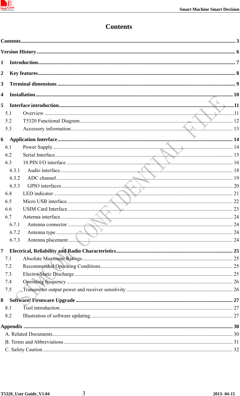
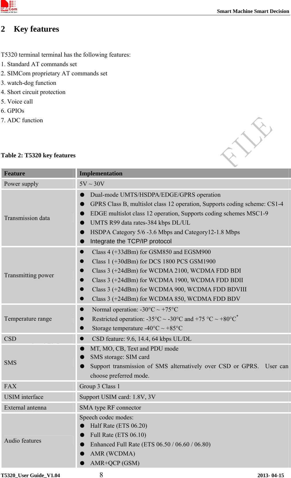
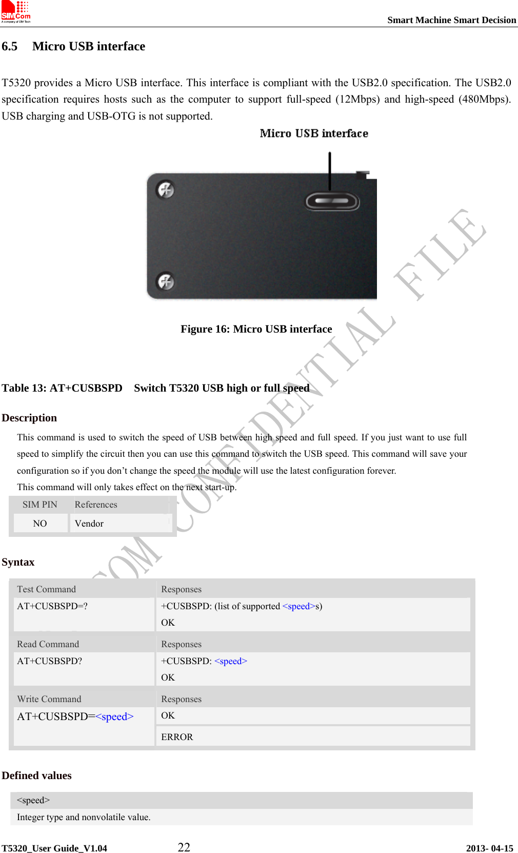
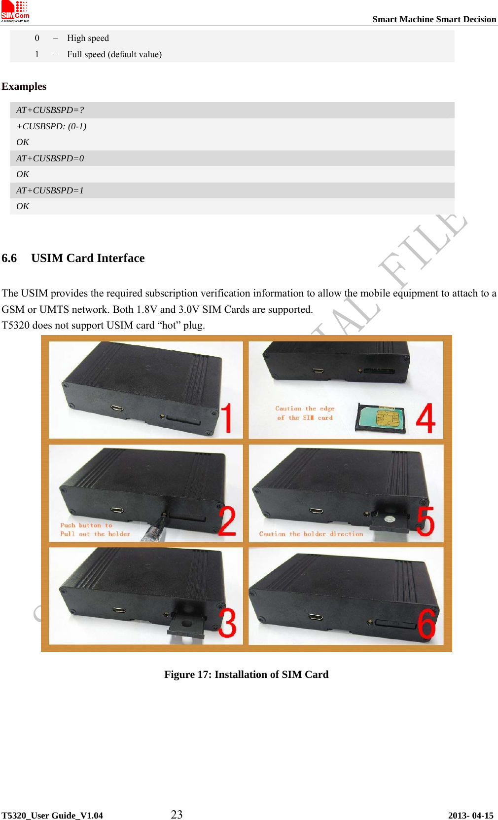
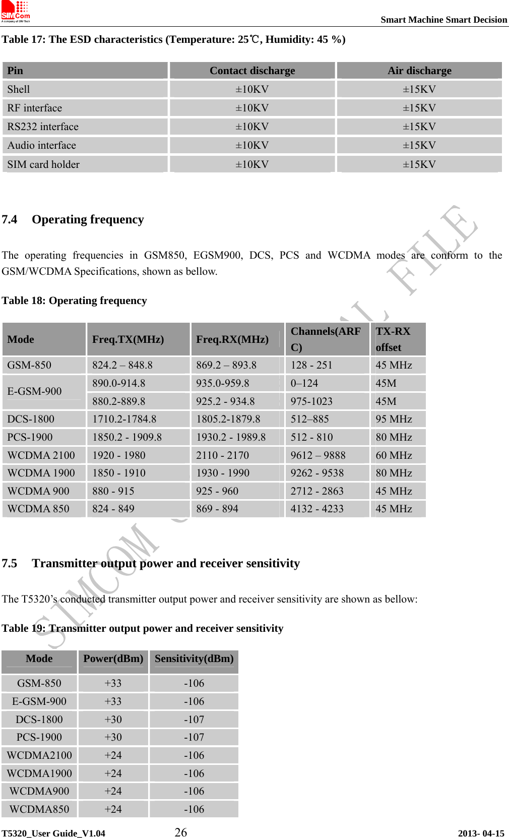
![Smart Machine Smart Decision T5320_User Guide_V1.04 20 2013- 04-15 Table 10: AT+CADC Read ADC Description Read the ADC value from modem. We support 3 type of ADC, raw type, temperature type and voltage type. SIM PIN References NO Vendor Syntax Test Command Responses AT+CADC=? +CADC: (range of supported <adc>s) OK Write Command Responses +CADC: <value> OK AT+CADC=<adc> ERROR Execution Command Responses AT+CADC Same as AT+CADC= 0: +CADC: <value> OK Defined values <adc> ADC type: 0 – raw type. 1 – temperature type. 2 – voltage type(mv) <value> Integer type value of the ADC. Examples AT+CADC=? +CADC:(0-2) OK AT+CADC=0 +CADC: 187 OK 6.3.3 GPIO interfaces T5320 provides 4 GPIO pins. All GPIOs can be configured as inputs or outputs. User can use AT Commands to read or write GPIOs status. Refer to document [1] for details.](https://usermanual.wiki/Simcom/2013060302.unser-manual/User-Guide-1998776-Page-20.png)
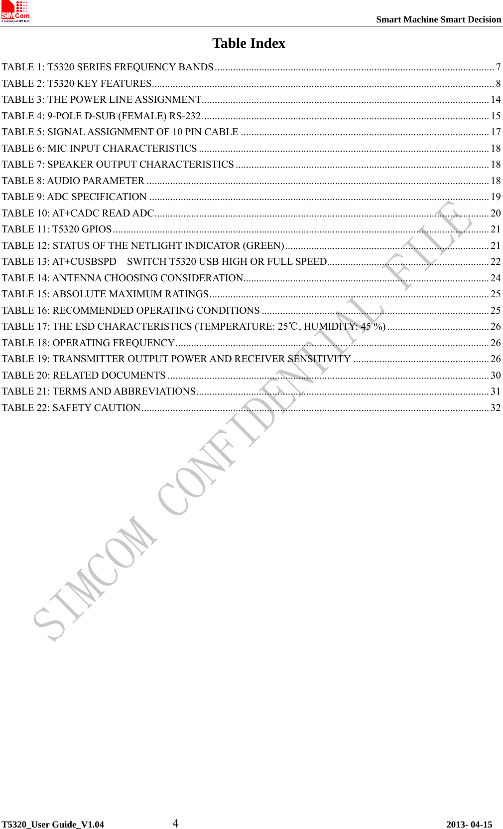
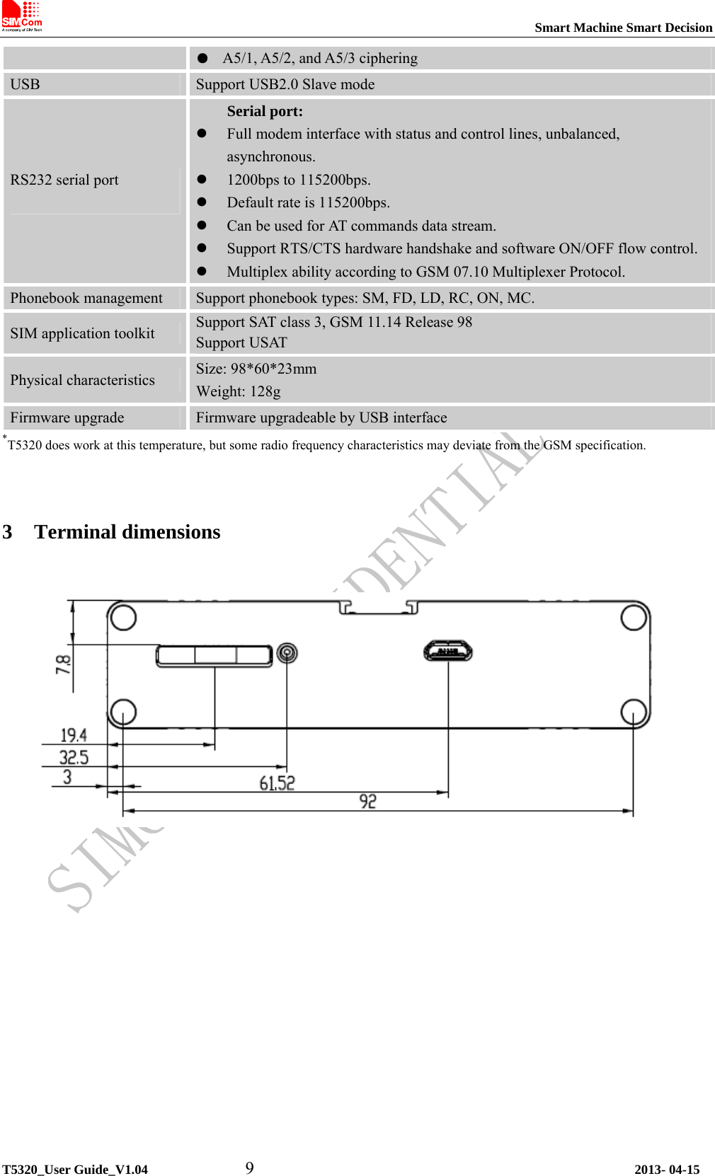
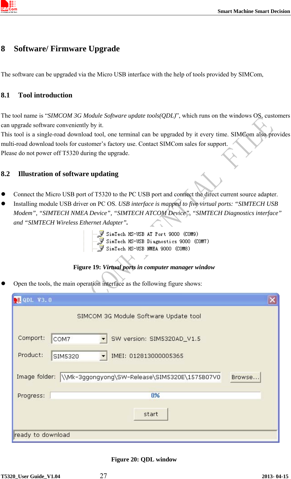
![Smart Machine Smart Decision Table 11: T5320 GPIOs T5320 GPIO CPU Pin No. I/O Function GPIO1 GPIO0 I/O General input/output PIN. It can be used as wake/interrupt signal to host from module If it is unused, left open. GPIO2 GPIO2 I/O General input/output PIN. GPIO3 GPIO3 I/O General input/output PIN. GPIO4 GPIO5 I/O General input/output PIN. Example 1: If user use T5320 GPIO1 pin as an output GPIO: 1) AT+CGDRT=0,1 //set T5320 GPIO1 to output 2) AT+CGSETV=0,1 //set T5320 GPIO1 to high value Example 2: If user use T5320 GPIO4 pin as an input GPIO: 1) AT+CGDRT=5,0 //set T5320 GPIO4 to input Please refer to document [1] and document [2] for details. 6.4 LED indicator A red led indicates the power status, when a valid power appears, the red led will lighten up. But a lighten up red led does not mean that the terminal has been powered up. A green led indicates the terminal status and GSM net status, after the terminal been powered up and registered to the network, it will blink at a certain frequency. Figure 15: Indicator LED Table 12: Status of the NETLIGHT indicator (Green) LED Status T5320 behavior Always On Searching Network/Call Connect 200ms ON, 200ms OFF Data Transmit 800ms ON, 800ms OFF Registered network Off Power off / Sleep T5320_User Guide_V1.04 21 2013- 04-15](https://usermanual.wiki/Simcom/2013060302.unser-manual/User-Guide-1998776-Page-21.png)
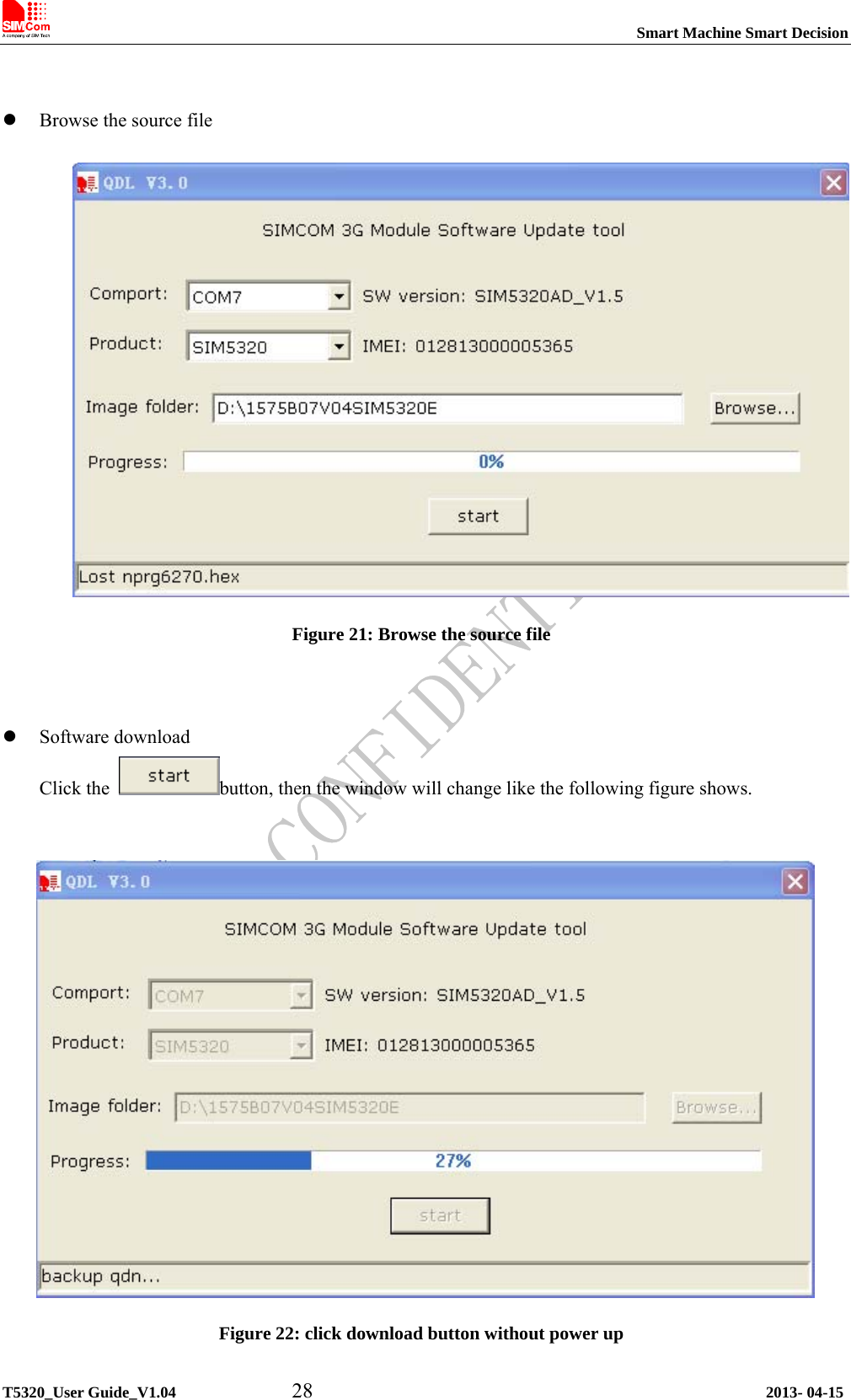
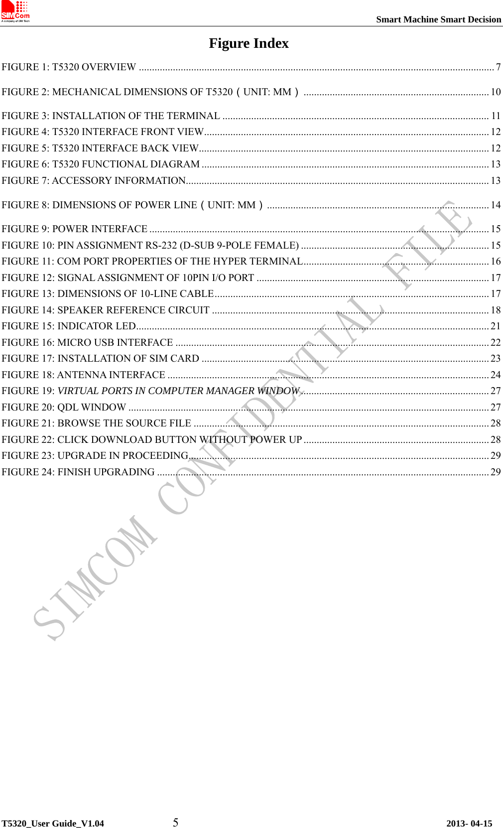
![Smart Machine Smart Decision T5320_User Guide_V1.04 30 2013- 04-15 Appendix A. Related Documents Table 20: Related documents SN Document name Remark [1] SIM5320_ATC SIM5320 AT Command Manual [2] SIM5xxx_GPIO_Application_note Applications Note About SIM5xxx_GPIO [3] Audio Application Note V1.01 Applications Note About T5320 Audio [4] ITU-T Draft new recommendationV.25ter Serial asynchronous automatic dialing and control [5] GSM 07.07 Digital cellular telecommunications (Phase 2+); AT command set for GSM Mobile Equipment (ME) [6] GSM 07.10 Support GSM 07.10 multiplexing protocol [7] GSM 07.05 Digital cellular telecommunications (Phase 2+); Use of Data Terminal Equipment – Data Circuit terminating Equipment (DTE – DCE) interface for Short Message Service (SMS) and Cell Broadcast Service (CBS) [8] GSM 11.14 Digital cellular telecommunications system (Phase 2+); Specification of the SIM Application Toolkit for the Subscriber Identity Module – Mobile Equipment (SIM – ME) interface [9] GSM 11.11 Digital cellular telecommunications system (Phase 2+); Specification of the Subscriber Identity Module – Mobile Equipment (SIM – ME) interface[10] GSM 03.38 Digital cellular telecommunications system (Phase 2+); Alphabets and language-specific information [11] GSM 11.10 Digital cellular telecommunications system (Phase 2); Mobile Station (MS) conformance specification; Part 1: Conformance specification [12] 3GPP TS 51.010-1 Digital cellular telecommunications system (Release 5); Mobile Station (MS) conformance specification [13] 3GPP TS 34.124 Electromagnetic Compatibility (EMC) for mobile terminals and ancillary equipment. [14] 3GPP TS 34.121 Electromagnetic Compatibility (EMC) for mobile terminals and ancillary equipment. [15] 3GPP TS 34.123-1 Technical Specification Group Radio Access Network; Terminal conformance specification; Radio transmission and reception (FDD) [16] 3GPP TS 34.123-3 User Equipment (UE) conformance specification; Part 3: Abstract Test Suites. [17] EN 301 908-02 V2.2.1 Electromagnetic compatibility and Radio spectrum Matters (ERM); Base Stations (BS) and User Equipment (UE) for IMT-2000. Third Generation cellular networks; Part 2: Harmonized EN for IMT-2000, CDMA Direct Spread (UTRA FDD) (UE) covering essential requirements of article](https://usermanual.wiki/Simcom/2013060302.unser-manual/User-Guide-1998776-Page-30.png)
![Smart Machine Smart Decision T5320_User Guide_V1.04 31 2013- 04-15 3.2 of the R&TTE Directive [18] EN 301 489-24 V1.2.1 Electromagnetic compatibility and Radio Spectrum Matters Electromagnetic Compatibility (EMC) standard for radio equipment and sPart 24: Specific conditions for IMT-2000 CDMA Direct Spread (UTRMobile and portable (UE) radio and ancillary equipment [19] IEC/EN60950-1(2001) Safety of information technology equipment (2000) [20] 3GPP TS 51.010-1 Digital cellular telecommunications system (Release 5); Mobile Statioconformance specification [21] GCF-CC V3.23.1 Global Certification Forum - Certification Criteria [22] 2002/95/EC Directive of the European Parliament and of the Council of 27 January 200restriction of the use of certain hazardous substances in electrical and elequipment (RoHS) B. Terms and Abbreviations Table 21: Terms and Abbreviations Abbreviation Description ADC Analog-to-Digital Converter AMR Adaptive Multi-Rate AT Attention commands CS Coding Scheme CSD Circuit Switched Data CTS Clear to Send DTE Data Terminal Equipment (typically computer, terminal, printer) DTR Data Terminal Ready DTU Data Transmit Unit DTX Discontinuous Transmission EFR Enhanced Full Rate EGSM Enhanced GSM ESD Electrostatic Discharge ETS European Telecommunication Standard FR Full Rate GPRS General Packet Radio Service GSM Global Standard for Mobile Communications HR Half Rate IMEI International Mobile Equipment Identity Li-ion Lithium-Ion MO Mobile Originated MS Mobile Station (GSM engine), also referred to as TE MT Mobile Terminated PAP Password Authentication Protocol PBCCH Packet Broadcast Control Channel PCB Printed Circuit Board PCL Power Control Level](https://usermanual.wiki/Simcom/2013060302.unser-manual/User-Guide-1998776-Page-31.png)