Simcom 2013072402 GSM/GPRS Wireless Data Module User Manual UDV 2013072402 EVB User Guide
Shanghai Simcom Ltd. GSM/GPRS Wireless Data Module UDV 2013072402 EVB User Guide
Simcom >
Contents
- 1. Evaluation Board Manual
- 2. User Manual
Evaluation Board Manual
SIM800L-EVB_User Guide_V1.00

Smart Machine Smart Decision
SIM800L-EVB_User Guide_V1.00 2 2013-07-22
Document Title: SIM800L-EVB_User Guide
Version: 1.00
Date: 2013-07-22
Status: Release
Document Control ID: SIM800L-EVB_User Guide_V1.00
General Notes
Simcom offers this information as a service to its customers, to support application and
engineering efforts that use the products designed by Simcom. The information provided is
based upon requirements specifically provided to Simcom by the customers. Simcom has not
undertaken any independent search for additional relevant information, including any
information that may be in the customer’s possession. Furthermore, system validation of this
product designed by Simcom within a larger electronic system remains the responsibility of
the customer or the customer’s system integrator. All specifications supplied herein are
subject to change.
Copyright
This document contains proprietary technical information which is the property of SIMCOM
Limited., copying of this document and giving it to others and the using or communication of
the contents thereof, are forbidden without express authority. Offenders are liable to the
payment of damages. All rights reserved in the event of grant of a patent or the registration of
a utility model or design. All specification supplied herein are subject to change without
notice at any time.
Copyright © Shanghai SIMCom Wireless Solutions Ltd. 2013

Smart Machine Smart Decision
SIM800L-EVB_User Guide_V1.00 3 2013-07-22
Contents
Contents ............................................................................................................................................ 3
Version History ................................................................................................................................. 4
1. SIM800L EVB .............................................................................................................................. 5
2. EVB Accessory ............................................................................................................................. 7
3. Accessory Interface ....................................................................................................................... 8
3.1 Power Interface ................................................................................................................... 8
3.2 Audio Interface .................................................................................................................... 8
3.3 SIM card interface ............................................................................................................... 9
3.4 RS232 Interface ................................................................................................................... 9
4. Illustration: .................................................................................................................................. 11
4.1 Running: ............................................................................................................................ 11
4.2 Connecting Net and calling ............................................................................................... 11
4.3 Downloading ..................................................................................................................... 11
4.4 Turns off ............................................................................................................................ 11
Figure Index
FIGURE 1: EVB TOP VIEW ................................................................................................................... 5
FIGURE 2: EVB BOTTOM VIEW .......................................................................................................... 6
FIGURE 3: EVB ACCESSORY ............................................................................................................... 7
FIGURE 4: POWER INTERFACE .......................................................................................................... 8
FIGURE 5: AUDIO INTERFACE ........................................................................................................... 8
FIGURE 6: SIM CARD INTERFACE ..................................................................................................... 9
FIGURE 8: SERIAL PORTS .................................................................................................................... 9

Smart Machine Smart Decision
SIM800L-EVB_User Guide_V1.00 4 2013-07-22
Version History
Data Version Description of change Author
2013-07-22 1.00 Origin Lee
Smart Machine Smart Decision
SIM800L-EVB_User Guide_V1.00 5 2013-07-22
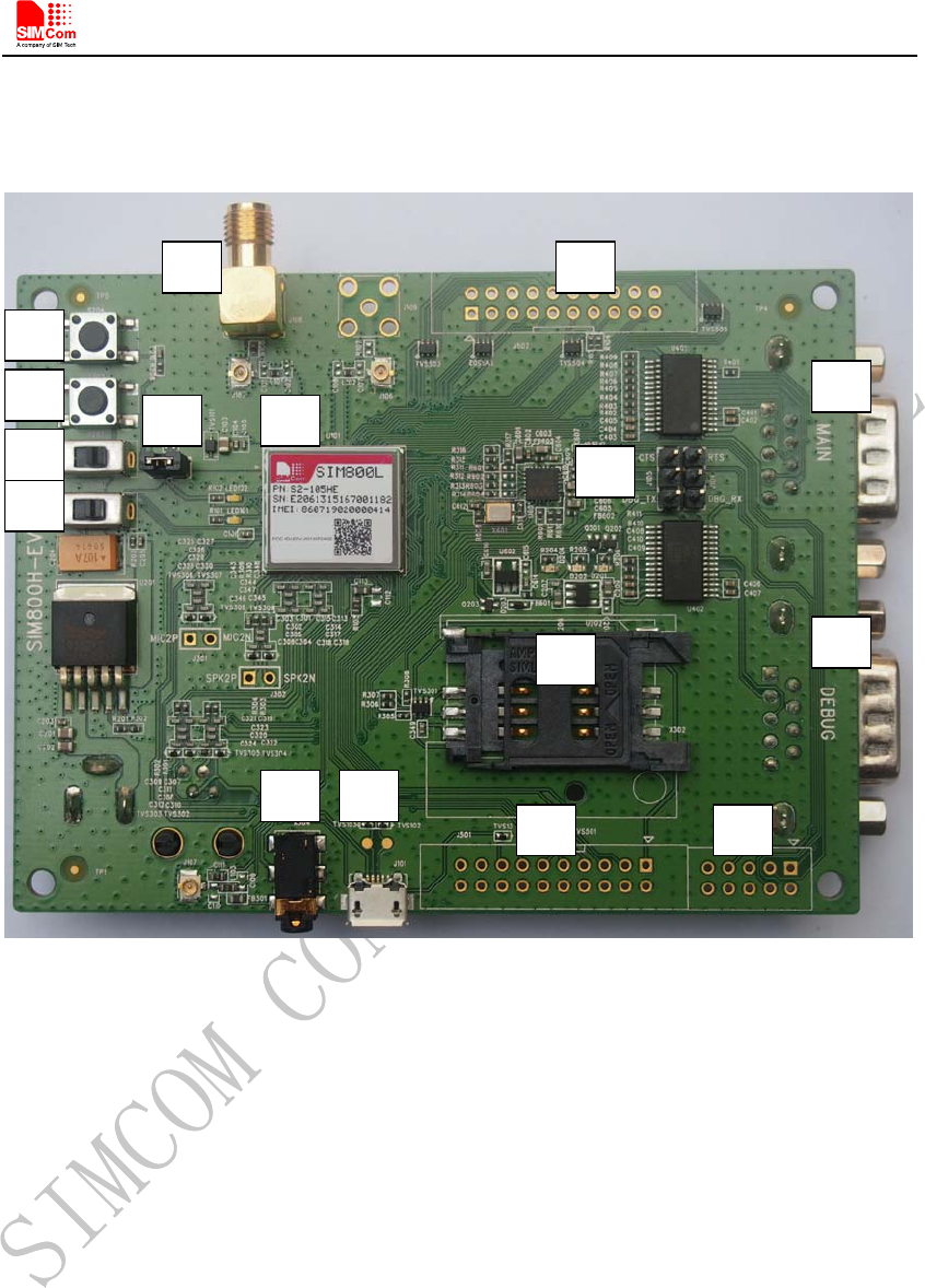
1. SIM800L EVB
Figure 1: EVB TOP view
A
A
B
C
D
E
M
L
J
I
H
N
F G O P
K
Smart Machine Smart Decision
SIM800L-EVB_User Guide_V1.00 6 2013-07-22
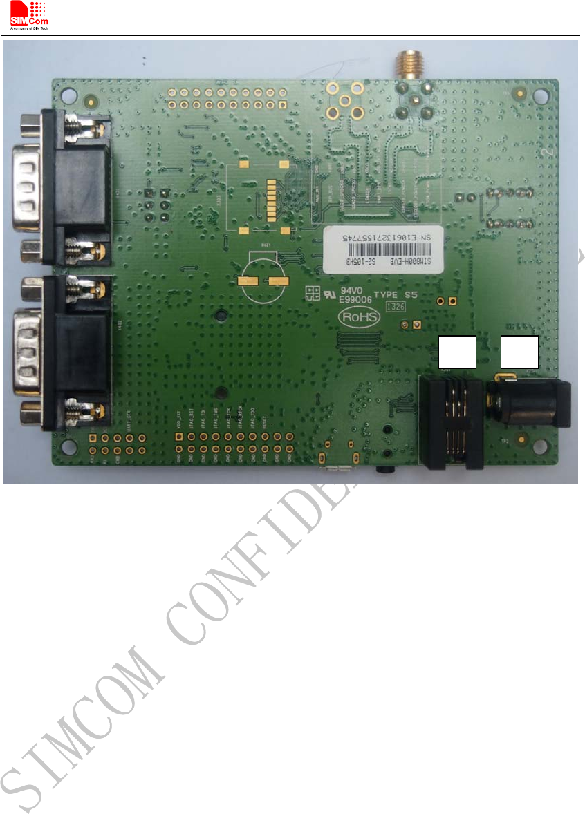
Figure 2: EVB BOTTOM view
A. SIM800L module
B. Power key ( module ON/OFF control )
C. Reset key ( reset the module )
D. Power switch ( download control )
E. Charge switch ( charge ON/OFF control )
F. Headset interface
G. USB
H. SIM card interface
I. Debug serial port
J. MAIN serial port
K. Test point interface
L. GSM antenna interface
M. Switch 1
N. Switch 2
O. Test point interface
P. Test point interface
Q. Headphones interface
R. Source adapter interface
Q R
Smart Machine Smart Decision
SIM800L-EVB_User Guide_V1.00 7 2013-07-22
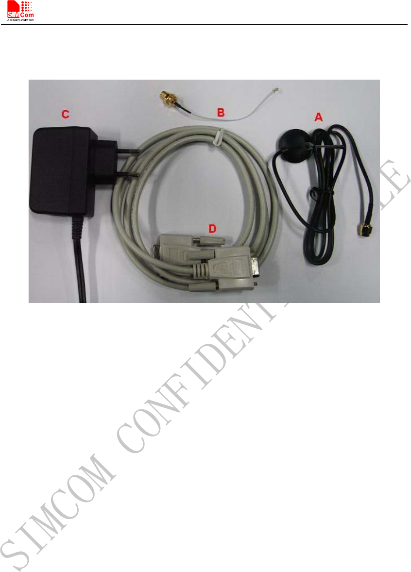
2. EVB Accessory
Figure 3: EVB accessory
A: GSM antenna
Model GSM antenna: WT-C&G-28-90
Frequency Range (MHz) 824 ~ 960 1710 ~ 1990
VSWR ≤1.5 (900MHz) ≤2 (1800MHz)
Gain: 3dBi
Input Impedance (Ω): 50
Polarization Type: Vertical
Connector Type: SMA
B: Antenna transmit line
C: 5V DC source adapter
D: Serial port line
NOTE: The maximum gain of the GSM antenna gain should not exceed 3dBi for end-users.
Smart Machine Smart Decision
SIM800L-EVB_User Guide_V1.00 8 2013-07-22
3. Accessory Interface
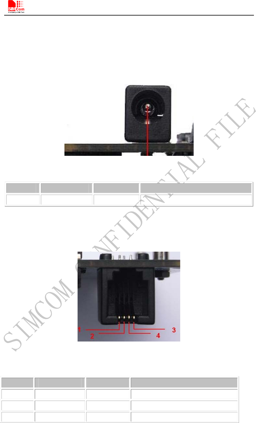
3.1 Power Interface
Figure 4: Power Interface
Pin Signal I/O Description
1 Adapter input I 5V/2.5A DC source input
3.2 Audio Interface
Figure 5: Audio Interface
Headset interface:
Pin Signal I/O Description
1 MIC1P I Positive microphone input
2 SPK1P O Positive receiver output
3 MIC1N I Negative microphone input
Smart Machine Smart Decision
SIM800L-EVB_User Guide_V1.00 9 2013-07-22
4 SPK1N O Negative receiver output
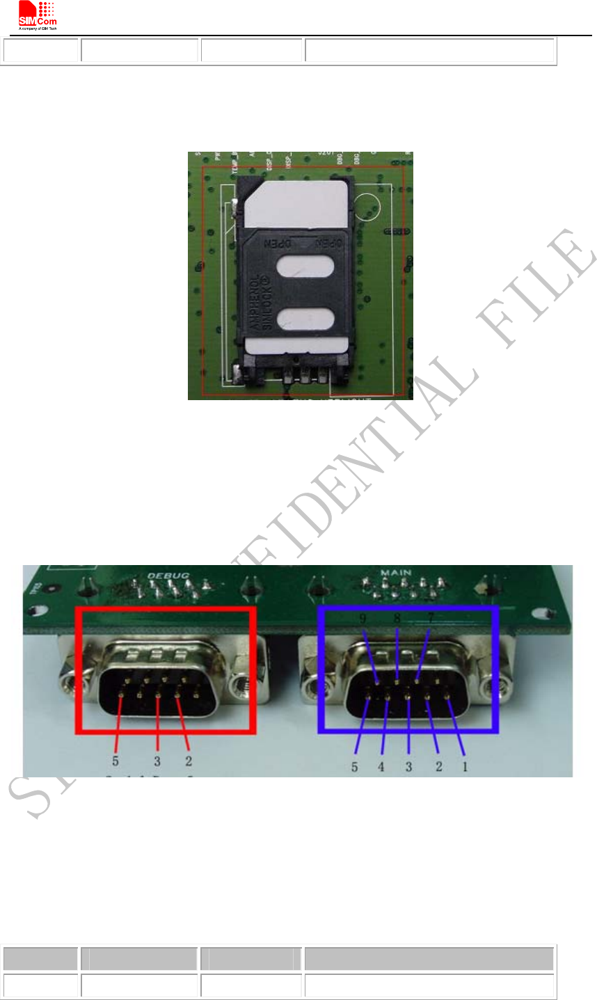
3.3 SIM card interface
Figure 6: SIM card interface
3.4 RS232 Interface
Figure 7: Serial Ports
Serial Port 1——MAIN Interface
Serial Port 2——DEGUG Interface
Main Interface:
Pin Signal I/O Description
1 DCD O Data carrier detection
Smart Machine Smart Decision
SIM800L-EVB_User Guide_V1.00 10 2013-07-22
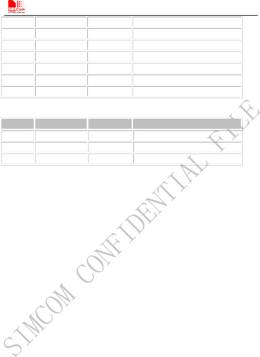
2 TXD O Transmit data
3 RXD I Receive data
4 DTR I Data Terminal Ready
5 GND GND
7 RTS I Request to Send
8 CTS O Clear to Send
9 RI O Ring Indicator
Debug Interface:
Pin Signal I/O Description
2 DEBUG_TX O Transmit data
3 DEBUG_RX I Receive data
5 GND GND

Smart Machine Smart Decision
SIM800L-EVB_User Guide_V1.00 11 2013-07-22
4. Illustration:
4.1 Running:
(1) Inserting 5V direct current source adapter, switching the S101,S102 switch on off state,
S105 switch on ON state;
(2) Press the PWRKEY for about 1 second, and then SIM800L module begins running.
You can see the light Q3 on the EVB flashing at a certain frequency. By the state, you can
judge whether the EVB and SIM800L can run or not. No function and test can be executed
when we have not connected necessary accessories.
4.2 Connecting Net and calling
(1) connect the serial port line to the MAIN serial port, open the HyperTerminal(AT
command windows) on your Personal computer, the location of the HyperTerminal in
windows2000 is START→accessory→communication→HyperTerminal. Set correct
Baud Rate and COM number. The Baud Rate of SIM800L is 115200, and the COM
number based on which USB port your serial port line insert in, you should select such
as COM3 or COM4 etc.
(2) Connect the antenna to the SIM800L-TE with SIM800L module using an antenna
transmit line, insert SIM card into the SIM card interface, insert headphones or headset
into its interface.
(3) Act on the step of running which mentioned above, power on the system, typing the
AT command in the HyperTerminal, and then the SIM800L module will execute its
corresponding function.
4.3 Downloading
Connect the serial port line to the MAIN serial port, connect the direct current source adapter, run
the download program and press the START key, then switch the S105 switch on ON state, S102
switch on ON state, then EVB provide the function of downloading.
4.4 Turns off
Turn off SIM800L module: press the PWRKEY for about 2 second, SIM800L module will be
turned off.

Smart Machine Smart Decision
SIM800L-EVB_User Guide_V1.00 12 2013-07-22
Contact us:
Shanghai SIMCom Wireless Solutions Ltd.
Add: SIM Technology Building,No.633,Jinzhong Road,Changning District,
Shanghai P.R. China 200335
Tel: +86 21 3235 3300
Fax: +86 21 3235 3301
URL: www.sim.com/wm