Simcom SIM5360A GSM/WCDMA Module User Manual SIM5360A EVB User Guide Rev 1
Shanghai Simcom Ltd. GSM/WCDMA Module SIM5360A EVB User Guide Rev 1
Simcom >
Contents
- 1. SIM5360A_EVB User Guide_Rev 1
- 2. SIM5360A_User Manual_Rev 1
SIM5360A_EVB User Guide_Rev 1
Development Kit Manual
SIM5360A_EVB_User Guide_V1.02

Document Title: SIM5360A EVB User Guide
Version: 1.02
Date: 2014-03-18
Status: Release
Document Control ID: SIM5360A_EVB_User Guide_V1.01
General Notes
SIMCOM offers this information as a service to its customers, to support application and
engineering efforts that use the products designed by SIMCOM. The information provided is
based upon requirements specifically provided to SIMCOM by the customers. SIMCOM has
not undertaken any independent search for additional relevant information, including any
information that may be in the customer’s possession. Furthermore, system validation of this
product designed by SIMCOM within a larger electronic system remains the responsibility of
the customer or the customer’s system integrator. All specifications supplied herein are
subject to change.
Copyright
This document contains proprietary technical information which is the property of SIMCOM
Limited., copying of this document and giving it to others and the using or communication of
the contents thereof, are forbidden without express authority. Offenders are liable to the
payment of damages. All rights reserved in the event of grant of a patent or the registration of
a utility model or design. All specification supplied herein are subject to change without
notice at any time.
Copyright © Shanghai SIMCom Wireless Solutions Ltd. 2014

Smart Machine Smart Decision
SIM5360A EVB User Guide 03.18.2014
2
Contents
Contents ............................................................................................................................................ 2
Figure Index ...................................................................................................................................... 2
Table Index ........................................................................................................................................ 3
Version History ................................................................................................................................. 3
1 Overview ........................................................................................................................................ 4
2 SIM5360 EVB ............................................................................................................................... 5
3 EVB accessories ............................................................................................................................. 8
4 Accessory Interface ........................................................................................................................ 9
4.1 Power Interface .................................................................................................................... 9
4.2 Audio Interface ................................................................................................................... 10
4.3 SIM card interface .............................................................................................................. 11
4.4 Antenna Interface ............................................................................................................... 12
4.5 RS232 Interface .................................................................................................................. 13
4.6 Operating Status LED ........................................................................................................ 13
4.7 USB interface ..................................................................................................................... 14
4.8 Switch interface .................................................................................................................. 15
4.9 IO interface ......................................................................................................................... 16
4.10 SD card interface .............................................................................................................. 18
4.10 UART2 to MicroUSB interface ........................................................................................ 19
5 EVB and accessory equipment..................................................................................................... 20
6 Quickly start ................................................................................................................................. 20
6.1 Running .............................................................................................................................. 20
6.2 Installing Driver ................................................................................................................. 21
6.3 Connecting Net and calling ................................................................................................ 21
6.4 Downloading ...................................................................................................................... 22
6.5 Turning off ......................................................................................................................... 22
Figure Index
FIGURE 1: EVB VIEW ........................................................................................................................... 6
FIGURE 2: EVB ACCESSORY ............................................................................................................... 8
FIGURE 3: POWER SELECTION JUMPER .......................................................................................... 9
FIGURE 4: AUDIO INTERFACE ......................................................................................................... 10
FIGURE 5: SIM CARD SOCKET ......................................................................................................... 11
FIGURE 6: MAIN AND DIVERSITY ANTENNA CONNECTOR ...................................................... 12
FIGURE 7:GPS ANTENNA CONNECTOR ......................................................................................... 12
FIGURE 8: SERIAL PORT .................................................................................................................... 13
FIGURE 9: STATUS LED ..................................................................................................................... 13
FIGURE 10: USB INTERFACE ............................................................................................................ 14
FIGURE 11: SWITCH INTERFACE ..................................................................................................... 15
FIGURE 12: IO INTERFACE ................................................................................................................ 16
FIGURE 13: SD CARD SOCKET ......................................................................................................... 18

Smart Machine Smart Decision
SIM5360A EVB User Guide 03.18.2014
3
FIGURE 14: MICROUSB INTERFACE ............................................................................................... 19
FIGURE 15: UART TO USB CIRCUIT ................................................................................................ 19
FIGURE 16: EVB AND ACCESSORY EQUIPMENT ......................................................................... 20
FIGURE 17: USB INTERFACE UPDATE PROCEDURE ................................................................... 22
Table Index
TABLE 1:SIM5360 EVB KEY FEATURES ............................................................................................ 4
TABLE 2: POWER SUPPLY ................................................................................................................... 9
TABLE 3: EARPHONE INTERFACE ................................................................................................... 10
TABLE 4: HEADSET INTERFACE ...................................................................................................... 10
TABLE 5: SIM CARD SOCKET ........................................................................................................... 11
TABLE 6: SERIAL INTERFACE .......................................................................................................... 13
TABLE 7: NETWORK STATUS LED .................................................................................................. 1 3
TABLE 8: USB INTERFACE ................................................................................................................ 14
TABLE 9: SWITCH INTERFACE ......................................................................................................... 15
TABLE 10: IO INTERFACE .................................................................................................................. 17
TABLE 11: SD CARD SOCKET ........................................................................................................... 18
Version History
Data Version Description of change Author
2014-01-22 1.01 Origin Libing
2014-03-18 1.02 Update to using SIM5360A-EVB V1.03 for description
Add UART2 to USB circuit
Libing
Smart Machine Smart Decision
SIM5360A EVB User Guide 03.18.2014
4
1 Overview
This document gives the usage of SIM5360A EVB, user can get useful information about the
SIM5360A EVB quickly through this document.
The Debug board is designed for customer to design their own applications by using the 3G
module SIM5360 easily.
All the functions of the SIM5360A can be used by this board. One can use UART, USB interface
to communicate with the SIM5360A. There is one UART interface, one USB 2.0 interface, one
SIM card interface, one T-FLASH card interface, three audio interfaces on the board.
One can connect the UART and/or the USB interface to a computer directly.
.
NOTE: This document is subject to change without notice at any time.
Table 1:SIM5360A EVB Key features
Feature Implementation
Power supply 1: DC 5.0V ~9.0V
2: USB 5.0V power supply
functions UART interface
USB2.0 interface
SIMCARD interface
IIC interface
Audio interface
ADC interface
POWER_ON key/Reset key
Flight mode switch
UART Control switch
TFLASH interface
UART to USB interface
Smart Machine Smart Decision
SIM5360A EVB User Guide 03.18.2014
5
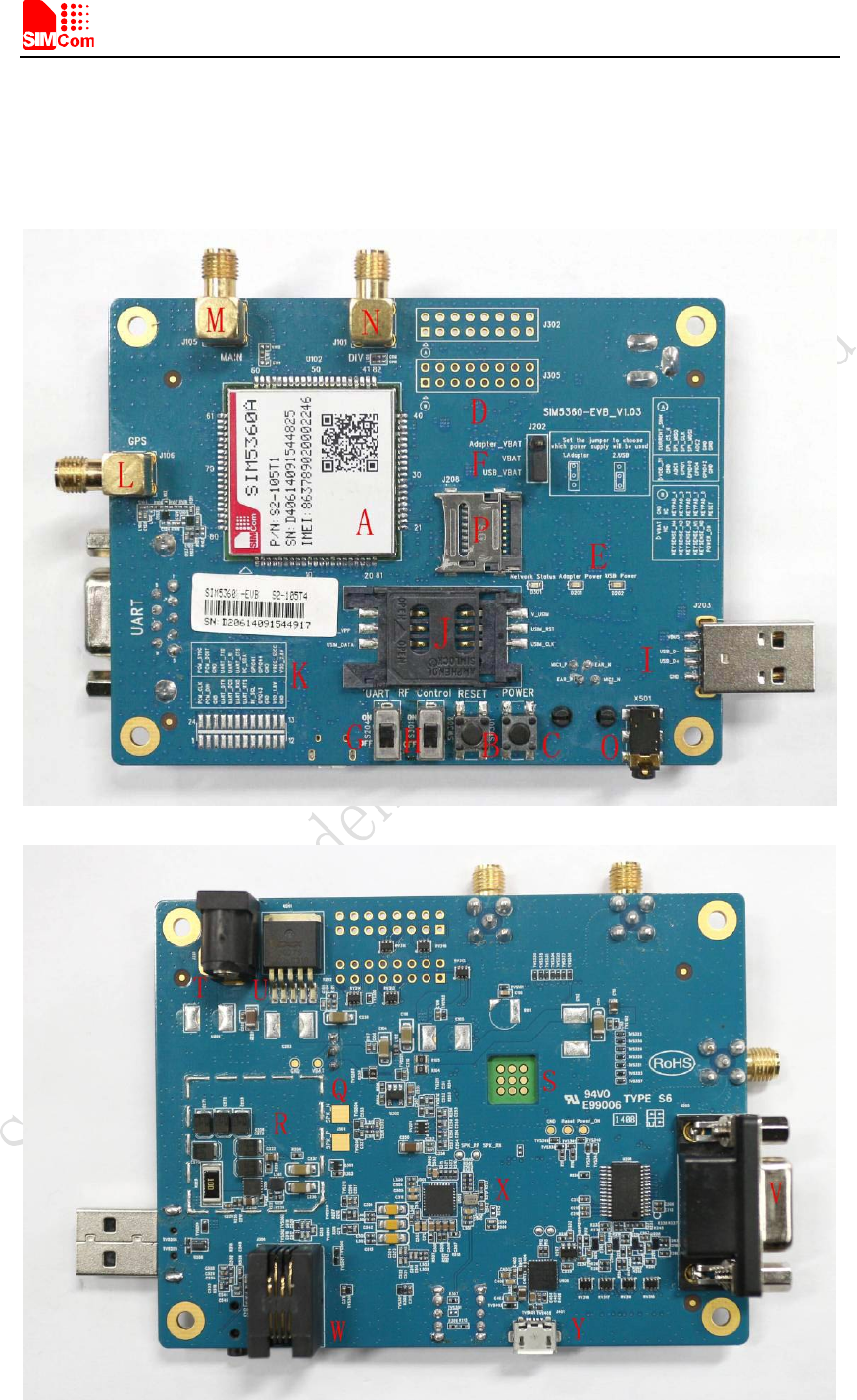
2 SIM5360A EVB

Smart Machine Smart Decision
SIM5360A EVB User Guide 03.18.2014
6
Figure 1: EVB view
A: SIM5360A module
B: Reset keypad
C: Power on/off keypad
D: IO interface 1(including GPIO, ADC, SPI, etc)
E: LED indicator(including network status,operating status)
F: Power supply selection jumper
G: UART enable/disable switch(If user wants to use UART, please switch it to ON at first.)
H: RF enable/disable (flight mode) switch (Before the SIM5360 is powered on, please make
sure that RF control switch is ON)
I: USB connector
J: SIM card socket
K: IO interface 2(including PCM,GPIO, UART, I2C, etc)
L: GPS/GLONASS antenna SMA
M: Main antenna SMA
N: Rx-diversity antenna SMA
O: Headset interface
P: SD card interface
Q: Speaker interface
R: USB DC-DC
S: SIM5360A JTAG test point
T: Adapter connector
U: DC LDO
V: UART interface for AT command transmitting, data exchanging
W: Handset interface(RJ-11)
X: Audio codec (WM8960)
Y: MicroUSB interface for SIM5360A (UART2 to USB, IC is Silabs Cp2103)
Smart Machine Smart Decision
SIM5360A EVB User Guide 03.18.2014
7
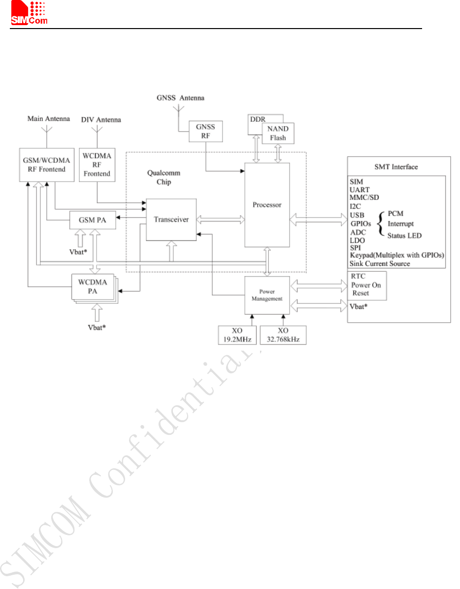
The following figure shows block diagram of SIM5360A EVB.
All hardware Sub-interfaces included in SIM5360A EVB are described in detail in following
chapters.
Smart Machine Smart Decision
SIM5360A EVB User Guide 03.18.2014
8
3 EVB accessories
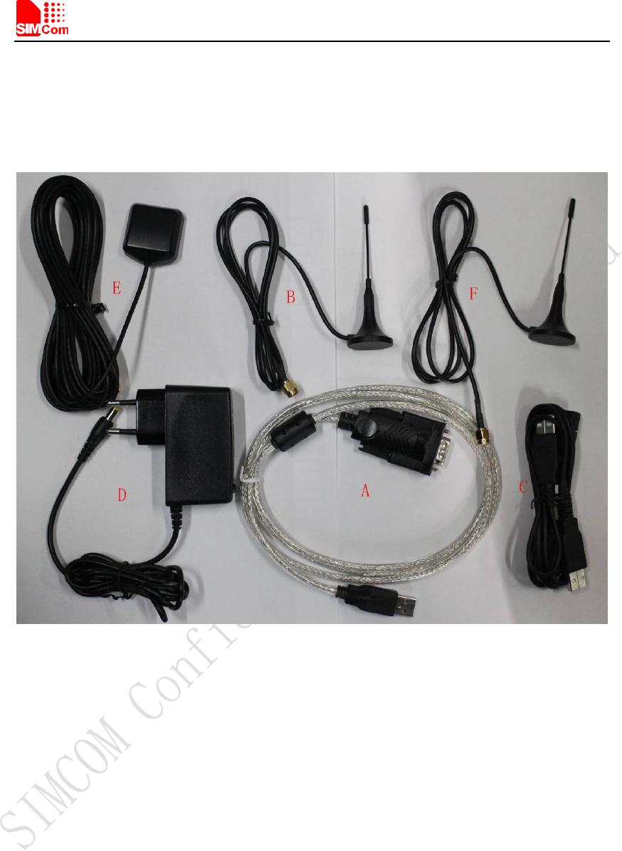
Figure 2: EVB accessory
A: USB to UART cable
B: MAIN antenna
Antenna Model: WT-C&G-28-90
Frequency Range (MHz) 824 ~ 960 1710 ~ 1990
VSWR ≤1.5 (900MHz) ≤2 (1800MHz)
Gain: 1dBi
Input Impedance (Ω): 50
Polarization Type: Vertical
Connector Type: SMA
C: USB cable
D: 5V DC adapter
E: GPS/GLONASS antenna
F: DIV antenna
NOTE: The maximum gain of the RF antenna gain should not exceed 1dBi for end-users.

Smart Machine Smart Decision
SIM5360A EVB User Guide 03.18.2014
9
4 Accessory Interface
4.1 Power Interface
Figure 3: Power selection jumper
Table 2: Power supply
Signal Input/Output Description
Adapter_VBAT O 3.8V/2A DC source input
USB_VBAT O 3.8V/0.5A DC source input
VBAT I SIM5360 DC source input
If user wants to use DC adapter as power supply, Adapter_VBAT should be connected to VBAT
on J202 through a jumper as following figure shows.
This board could be powered by USB bus. User should connect the USB pin. USB_VBAT is the
USB power out.If user wants to use USB VBUS to power up the module, please connect
connector VBAT with connector USB_VBAT as following figure shows.and disconnect
Adapter_VBAT.
Smart Machine Smart Decision
SIM5360A EVB User Guide 03.18.2014
10
4.2 Audio Interface
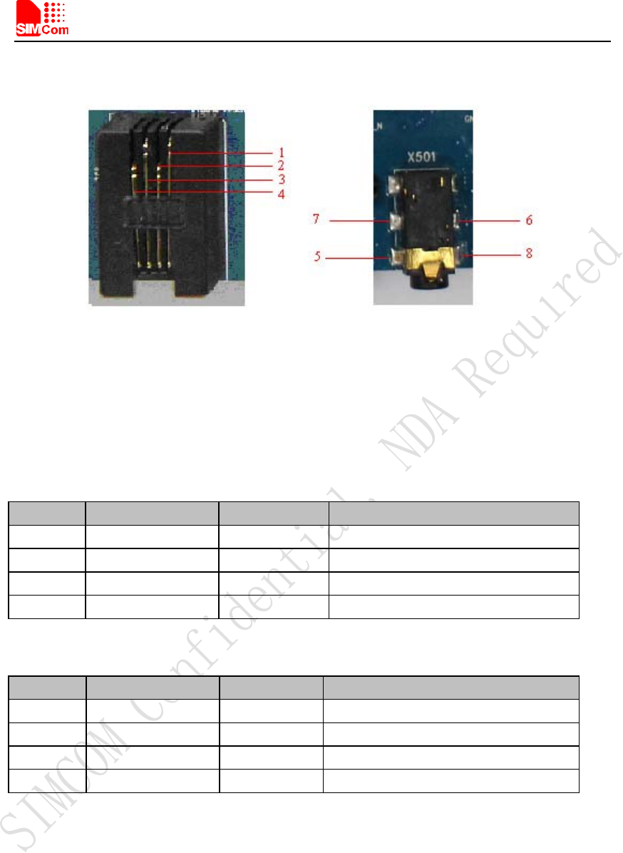
Figure 4: Audio Interface
J306 is the handset interface. X501 is the headset interface.
NOTE: The MIC’s polarity must be correct.
Table 3: Earphone interface
Pin Signal Input/Output Description
1 MIC1P I Positive microphone input
2 EAR_P O Positive receiver output
3 EAR_N O Negative receiver output
4 MIC1N I Negative microphone input
Table 4: Headset interface
Pin Signal I/O Description
5 GND Ground
6 HEADSET_MIC+ I Headset microphone input
7 HPH_L O Positive microphone output
8 HPH_R O Negative microphone output
Speaker interface:
Please refer Figure 1. Pin 1 and Pin 2 is the SPK_M and SPK_P on J501.
NOTE: Audio cable must be away from the RF antenna, otherwise TDD noise may be occurred.
Smart Machine Smart Decision
SIM5360A EVB User Guide 03.18.2014
11
4.3 SIM card interface
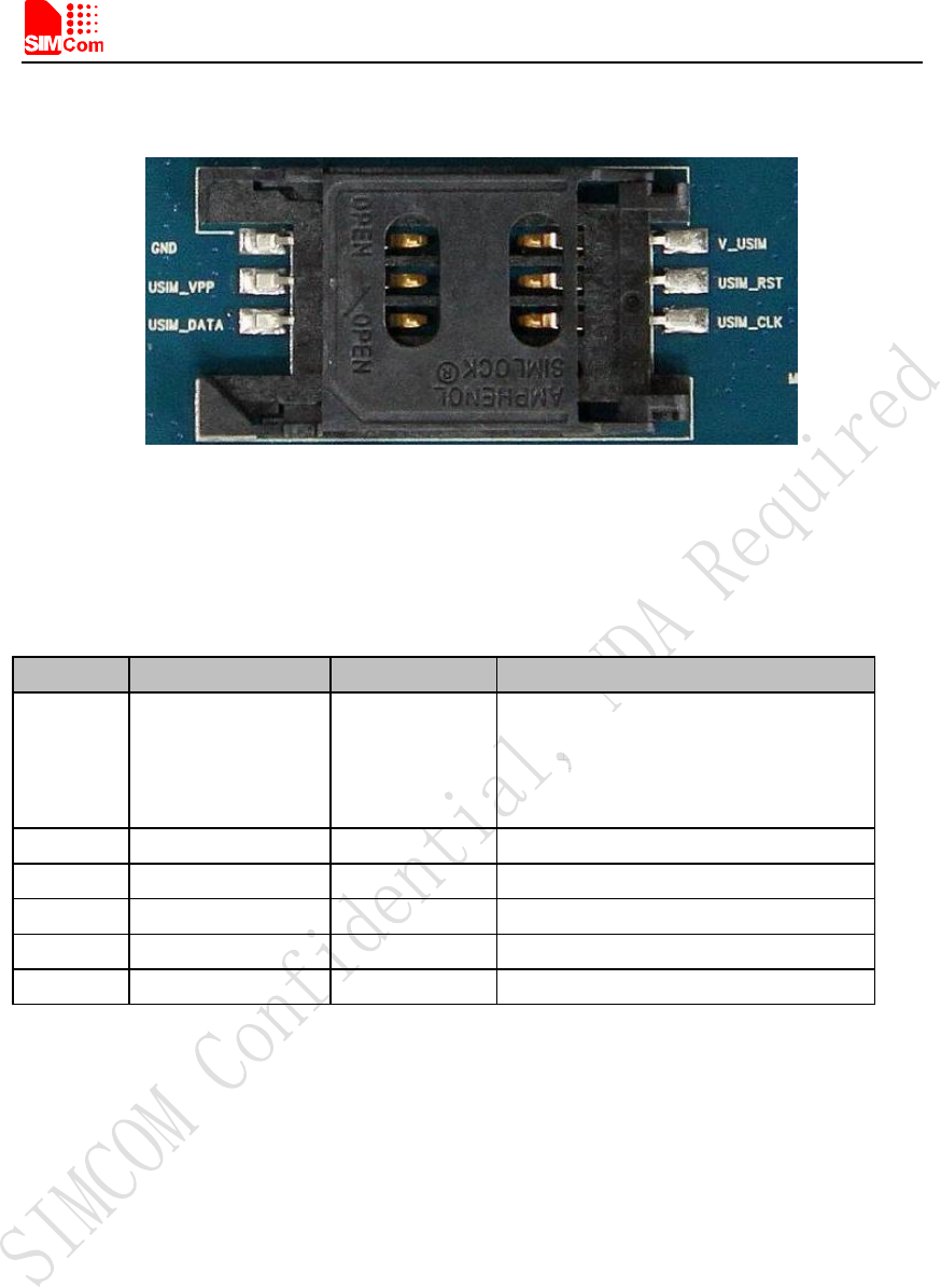
Figure 5: SIM card socket
Table 5: SIM card socket
Pin Signal Input/Output Description
1
V_USIM O
USIM Card Power output automatic
output on USIM mode,one is
3.0V±10%, another is 1.8V±10%.
Current is about 10mA.
2 USIM_RESET O USIM Card Reset
3 USIM_CLK O USIM Card Clock
4 GND Ground
5 SIM_VPP Not connect
6 USIM_DATA I/O USIM Card data I/O
Smart Machine Smart Decision
SIM5360A EVB User Guide 03.18.2014
12
4.4 Antenna Interface
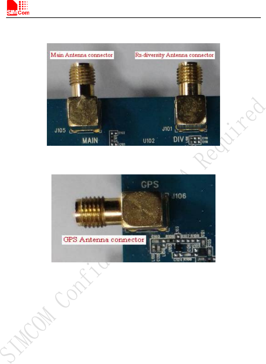
Figure 6: Main and diversity Antenna connector
Figure 7:GPS Antenna connector
SIMCom strongly recommends additional matching components between the antenna and the RF
output of SIM5360 RF PAD (Main: pin 59; Diversity: PIN 82; GPS: pin 79;) for the application
including an antenna.
Topology is a PI structure plus a serial element; components assume to be capacitors or inductors
depending on the antenna matching. But if the pad is 50 Ohms and is connected to 50 Ohms load,
the matching circuitry is not needed.
The RF connection should be short enough to minimize losses and must have a characteristic
impedance of 50 Ohms until F ≥ 2 GHz.
SIMCom strongly recommends the micro strip line can be used.
Smart Machine Smart Decision
SIM5360A EVB User Guide 03.18.2014
13
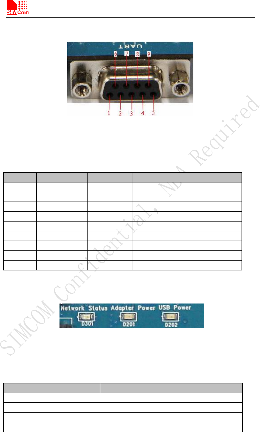
4.5 RS232 Interface
Figure 8: Serial Port
J205 is 9 pins standard RS232 UART interface. It can be connected to a PC directly.
Table 6: Serial Interface
Pin Signal I/O Description
1 DCD O Data carrier detection
2 TXD O Transmit data
3 RXD I Receive data
4 DTR I Data Terminal Ready
5 GND Ground
6 NC NC
7 RTS I Request to Send
8 CTS O Clear to Send
9 RI O Ring Indicator
4.6 Operating Status LED
Figure 9: Status LED
Table 7: Network status LED
D301 Status Module Status
Off Module is not running
On Module is running, or voice call is connected
800ms On/ Off Module find the network and registered
200ms On/ Off Data communication
Smart Machine Smart Decision
SIM5360A EVB User Guide 03.18.2014
14
LED I/O Description
D201 O ADAPTER power indicator
D202 O USB power indicator
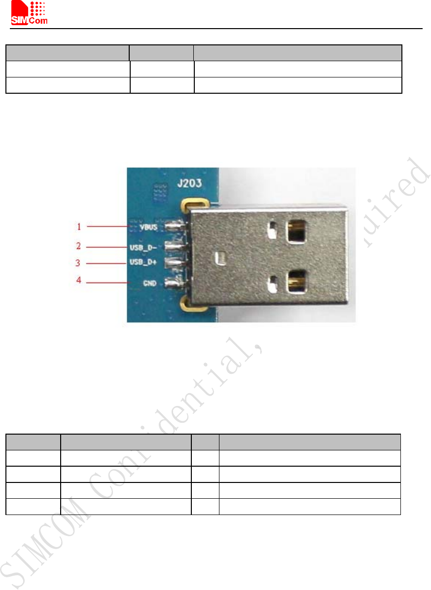
4.7 USB interface
Figure 10: USB Interface
It is a normal 4Pin USB connector.
Table 8: USB interface
Pin Signal I/O Description
1 USB_VBUS I 5V
2 USB_DM I/O D+ line
3 USB_ DP I/O D- line
4 GND Ground
Smart Machine Smart Decision
SIM5360A EVB User Guide 03.18.2014
15
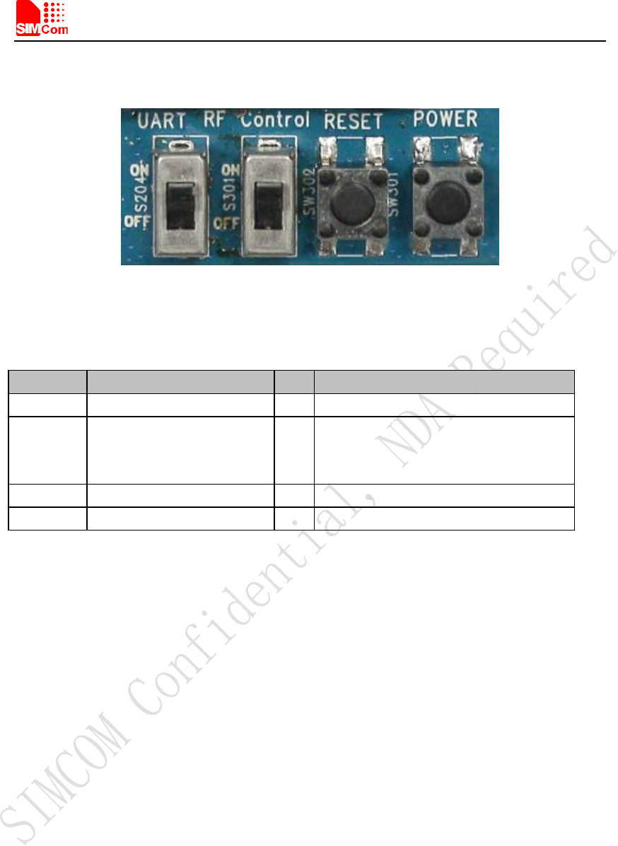
4.8 Switch interface
Figure 11: Switch Interface
Table 9: Switch interface
Switch Signal I/O Description
1 RS232 chip SHUTDOWN I UART switch
2 GPIO4 I RF switch (S301)
ON : Normal mode
OFF : Flight mode
3 RESET I Reset the module
4 PWRER_ON I Power on the module
Smart Machine Smart Decision
SIM5360A EVB User Guide 03.18.2014
16
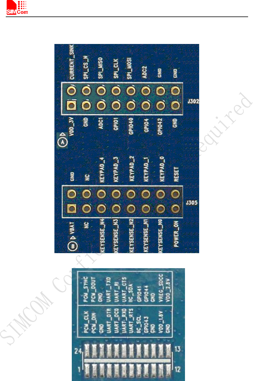
4.9 IO interface
Figure 12: IO Interface

Smart Machine Smart Decision
SIM5360A EVB User Guide 03.18.2014
17
Table 10: IO interface
Signal I/O Description
GPIO40 I/O GPIO
POWER_ON I Power on the module
RESET I Reset the module
GPIO41 I/O GPIO
GPIO43 I/O GPIO
GPIO44 I/O GPIO
VDD_3V O 3V power supply
CURRENT_SINK I Current sink source
ADC1 I ADC
GPIO1 O Network status
GPIO4 I RF control switch
GPIO42 I/O GPIO
SPI_CS_N O SPI Chip selection
SPI_MISO
(UART_RXD)
I SPI Master input Slave output / Receive data of
UART2
SPI_MOSI
(UART_TXD)
O SPI Master output Slave input / Transmit data of
UART2
ADC2 I ADC
KEYSENSE_N0 I Bit 0 for sensing key press on pad
matrix
KEYSENSE_ N1 I Bit 1 for sensing key press on pad
matrix
KEYSENSE_ N2 I Bit 2 for sensing key press on pad
matrix
KEYSENSE_ N3 I Bit 3 for sensing key press on pad
matrix
KEYSENSE_ N4 I Bit 4 for sensing key press on pad
matrix
KEYPAD_0 O Bit 0 drive to the pad matrix
KEYPAD_1 O Bit 1 drive to the pad matrix
KEYPAD_2 O Bit 2 drive to the pad matrix
KEYPAD_3 O Bit 3 drive to the pad matrix
KEYPAD_4 O Bit 4 drive to the pad matrix
I2C_SDA I/O I2C data
I2C_SCL O I2C clock
PCM_DIN/GPIO0 I General input pin for module wake up interrupt. It
also can be multiplexed as the PCM_DIN pin.
PCM_SYNC/GPIO2 I General input pin. It also can be multiplexed as the
PCM_SYNC pin.
PCM_CLK/GPIO3 O General output pin. It also can be multiplexed as the
Smart Machine Smart Decision
SIM5360A EVB User Guide 03.18.2014
18
PCM_CLK pin.
PCM_DOUT/GPIO5 O General output pin. It also can be multiplexed as the
PCM_DOUT pin.
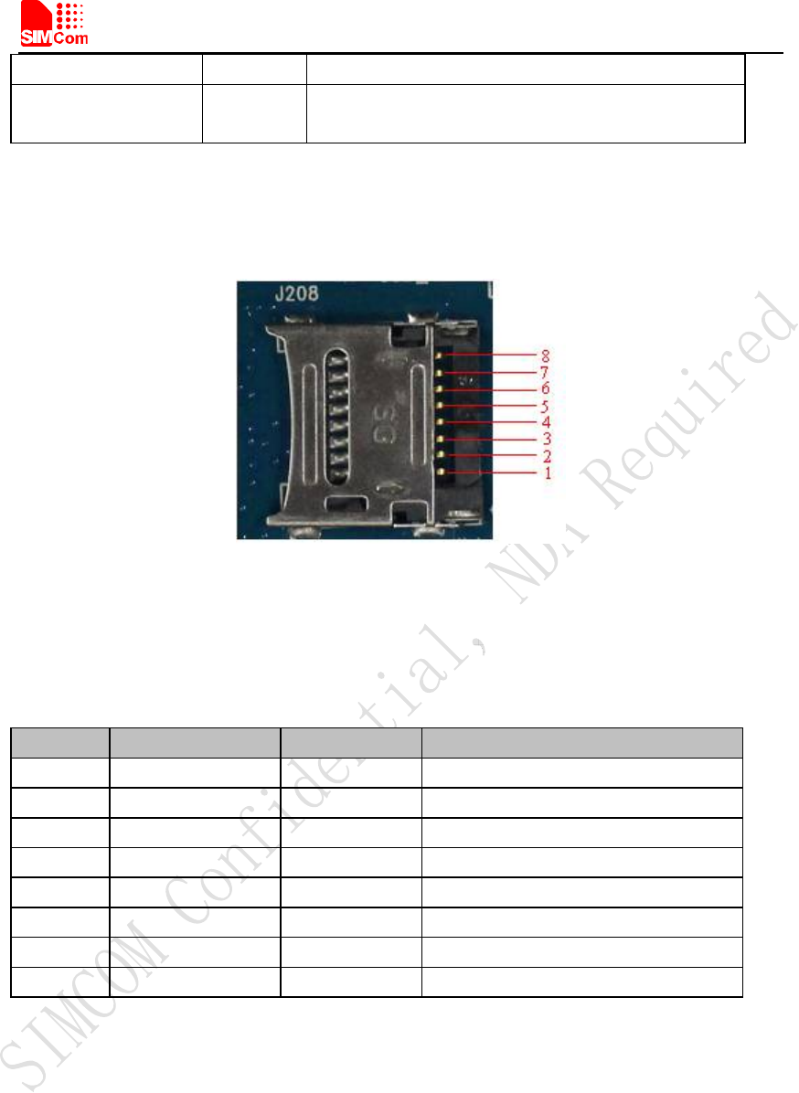
4.10 SD card interface
Figure 13: SD card socket
J208 is the SD card interface.
Table 11: SD card socket
Pin Signal Input/Output Description
1 SD_D2 I/O Data line 2
2 SD_D3 I/O Data line 3
3 SD_CMD O Command line
4 VREG_SDCC O Power supply for SD card
5 SD_CLK O Clock line
6 GND Ground
7 SD_D0 I/O Data line 0
8 SD_D1 I/O Data line 1
Smart Machine Smart Decision
SIM5360A EVB User Guide 03.18.2014
19
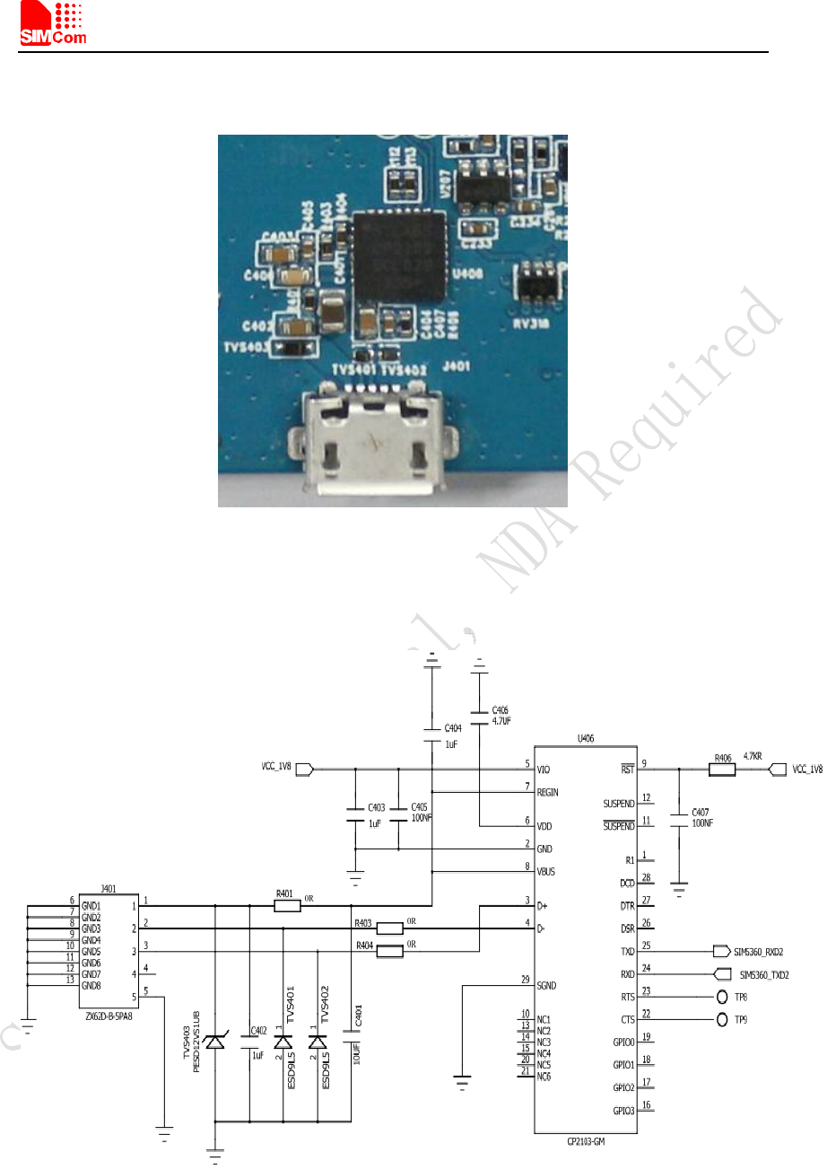
4.10 UART2 to MicroUSB interface
Figure 14: MicroUSB interface
J401 is 5 pins standard MicroUSB interface. It can be connected to a PC directly.
The following figure is the uart to USB circuit of SIM5360-EVB.
Figure 15: Uart to USB circuit
Smart Machine Smart Decision
SIM5360A EVB User Guide 03.18.2014
20
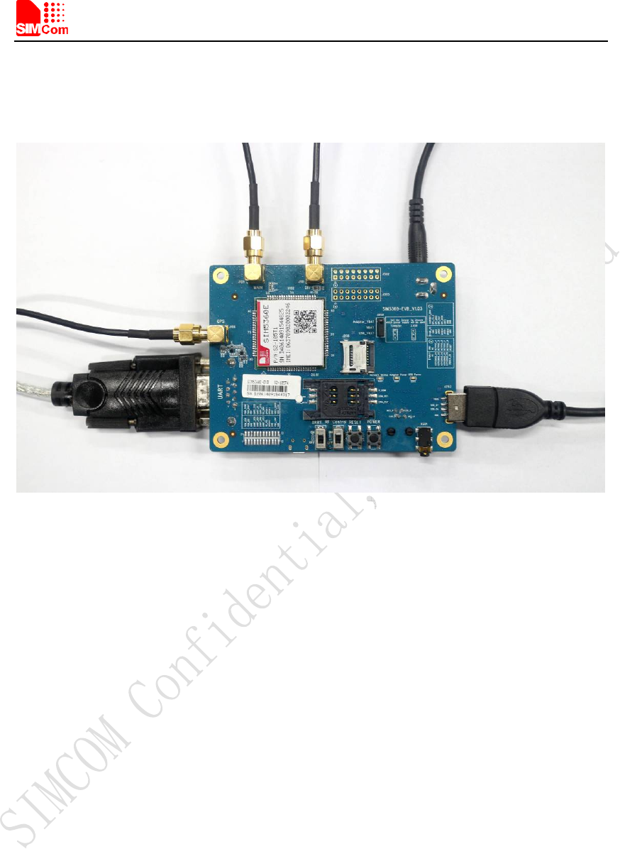
5 EVB and accessory equipment
At normal circumstance, the EVB and its accessories are equipped as the Figure below.
Figure 16: EVB and accessory equipment
6 Quickly start
6.1 Running
There are two ways to provide power supply to SIM5360 module: one is to use the 5V power
supply provided in the EVB kit; the other is to use USB port of personal computer.
(1) When user use the power supply, if user insert 5V DC source adapter, user should connect
ADAPTER_VBAT pin and VBAT pin on the EVB board; then insert a valued SIM card and
check if the antenna is connected, and make sure that RF control switch is set to ON; finally
press the on/off switch for about 1 second, and then SIM5360 module will begin running.
(2) Another option is to use USB port of Computer as power supply. To do so, user need to
connect USB_VBAT pin and VBAT pin on the EVB board, and make sure that RF control
switch is set to ON. Firstly insert the sim card and connect the antenna, then connect the PC
with USB-to-USB cable and press the Power_ON button for one second, then SIM5360 will
start running.

Smart Machine Smart Decision
SIM5360A EVB User Guide 03.18.2014
21
User can see the light on the EVB flashing at a certain frequency about 1.25Hz. By the state,
user can judge whether the EVB and SIM5360 is running or not. No function and test can be
executed if user has not connected necessary accessories.
NOTE: This EVB board supports USB power supply when user connects USB_VBAT and
VBAT together.
6.2 Installing Driver
There are 3 ways to connect the module to user’s computer and communicate via HyperTerminal:
(1) Using USB-TO-USB cable;
(2) Using UART-TO-USB cable;
(3) Using UART-TO-UART cable.
In the first case, user need install the module USB driver, which can be got from our FAE or sales;
For the UART to USB driver, user may get it from the CD in the EVB kit; If user use UART to
UART cable, there are certain points to be noticed. One can use UART to UART cable in EVB kit,
if the customers want to use their own UART to UART cable, please make sure that the pin
sequences of it is same as those of cable in EVB kit, pin sequences of which are shown in Figure
9.
6.3 Connecting Net and calling
Once user installs the driver, user can follow steps below to connect to Network.
(1) When user use a UART-UART cable, user need to connect the serial port line to the serial port,
open the HyperTerminal (AT command windows) on user’s Personal computer. The location of
the HyperTerminal in windows2000/XP/Vista can be found from START→accessory→
communication→HyperTerminal. Please set the correct Baud Rate and COM port number, the
Baud Rate of SIM5360 is 115200, and the COM port number is based on which UART port user’s
serial port line is inserted, user should select the port such as COM1 or COM2 etc.
(2) Connect the antenna to the SIM5360 module using an antenna transmit line, insert SIM card
into the SIM card holder, and insert handset into its sockets.
(3) Follow the steps of running which has been mentioned above in Sector 5.1, power on the
system, type the AT command from the HyperTerminal, and then the SIM5360 module will
execute its corresponding function. For example, if user type “AT”, then it should respond “OK”;
if user type “ATI”, it should display product identification information.
(4) If user want to use USB to USB cable, user need to connect the cable to USB port of the
module and the computer, then follow step 1~3.
Smart Machine Smart Decision
SIM5360A EVB User Guide 03.18.2014
22
(5) If user use UART to USB cable, user need to connect the cable to module serial port and the
USB port of the computer, then follow step 1~3.
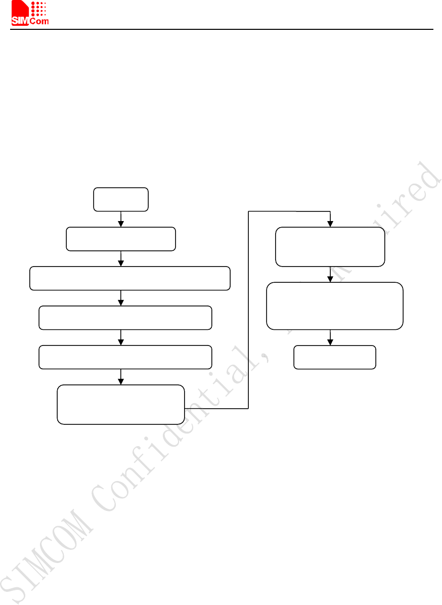
6.4 Downloading
Connect the USB port line to the USB port, connect the direct current source adapter, run the
download program, and choose the correct image, please follow the QDL downloading menu for
the operation. Update procedure is described in the figure below.
Figure 17: USB interface update procedure
6.5 Turning off
Press the POWER_ON for about 1 second, SIM5360 module will be turned off.
NOTE: If user uses USB to power on the module, just disconnect the USB cable to turn off.
START
Module power on
Connect module USB slot and PC by USB cable
Install module driver on windows OS.
Close all app software which
use USB virtual
p
orts
Double click QDL.exe,
u
p
date be
g
in
Waiting until download finish,
QDL quit out automatically
Update success
Copy new firmware into QDL data folder

Smart Machine Smart Decision
SIM5360A EVB User Guide 03.18.2014
23
Contact us:
Shanghai SIMCom Wireless Solutions Ltd.
Add: Building A,SIM Technology Building,No.633,Jinzhong Road,Changning
Disdrict,Shanghai P.R. China 200335
Tel: +86-21-3252 3300
Fax: +86-21-3252 3301
URL: www.sim.com