Simcom SIM7100A LTE/WCDMA Module User Manual UDV SIM7100A EVB User Guide
Shanghai Simcom Ltd. LTE/WCDMA Module UDV SIM7100A EVB User Guide
Simcom >
Contents
- 1. UDV-SIM7100A_User Manual
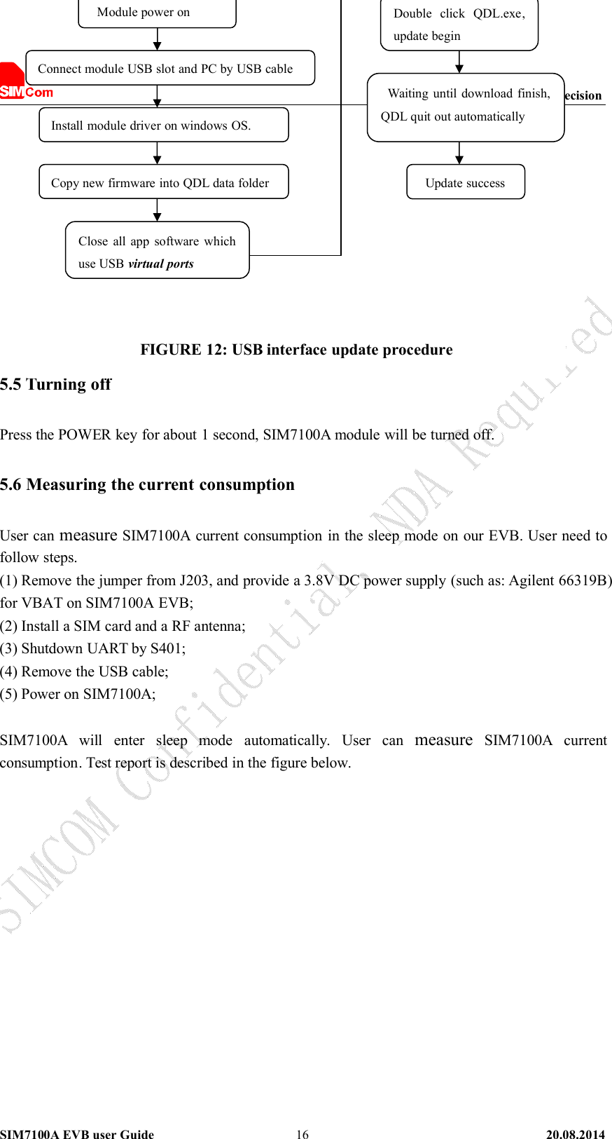
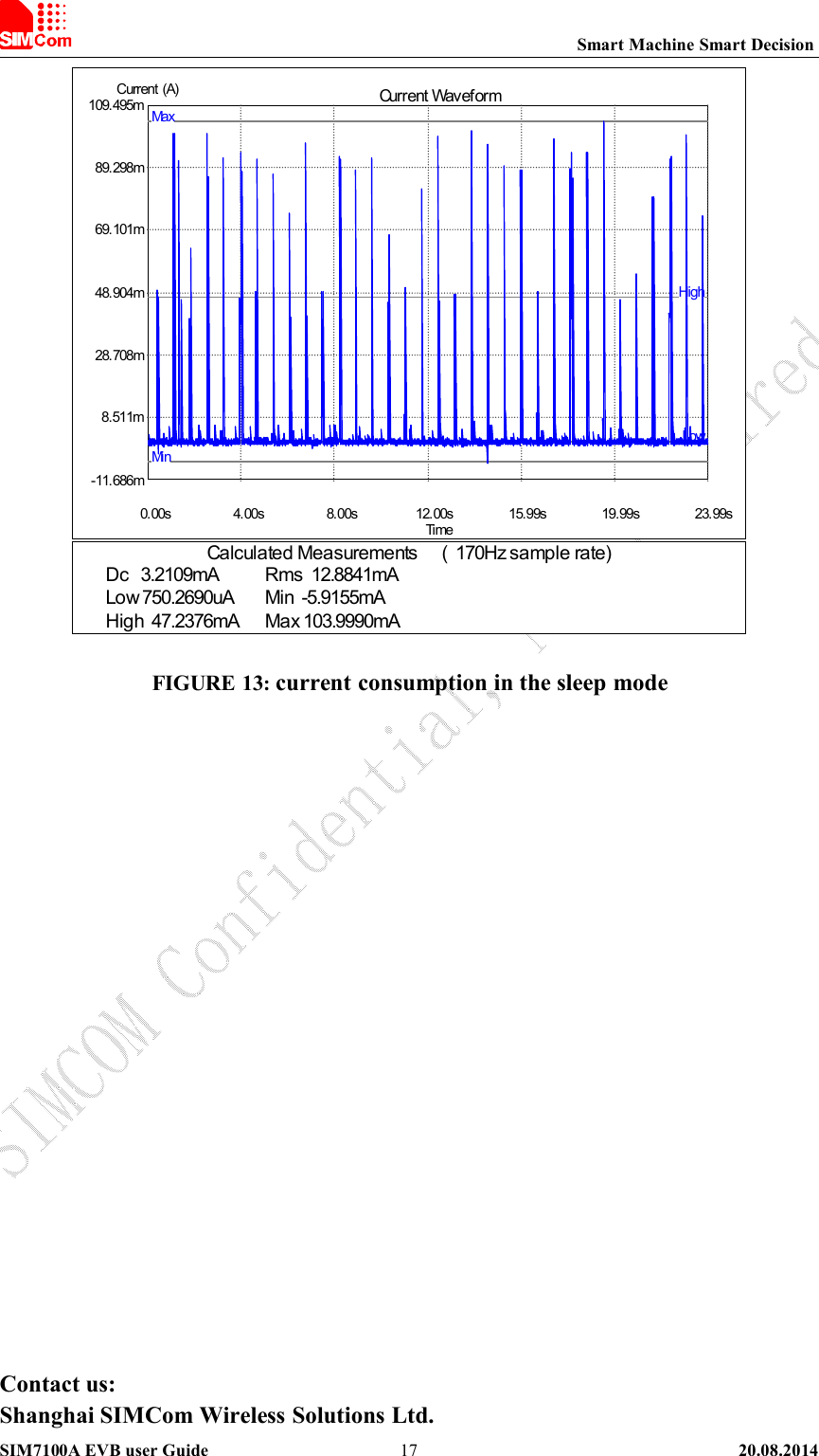
- 2. UDV-SIM7100A_EVB_User Guide
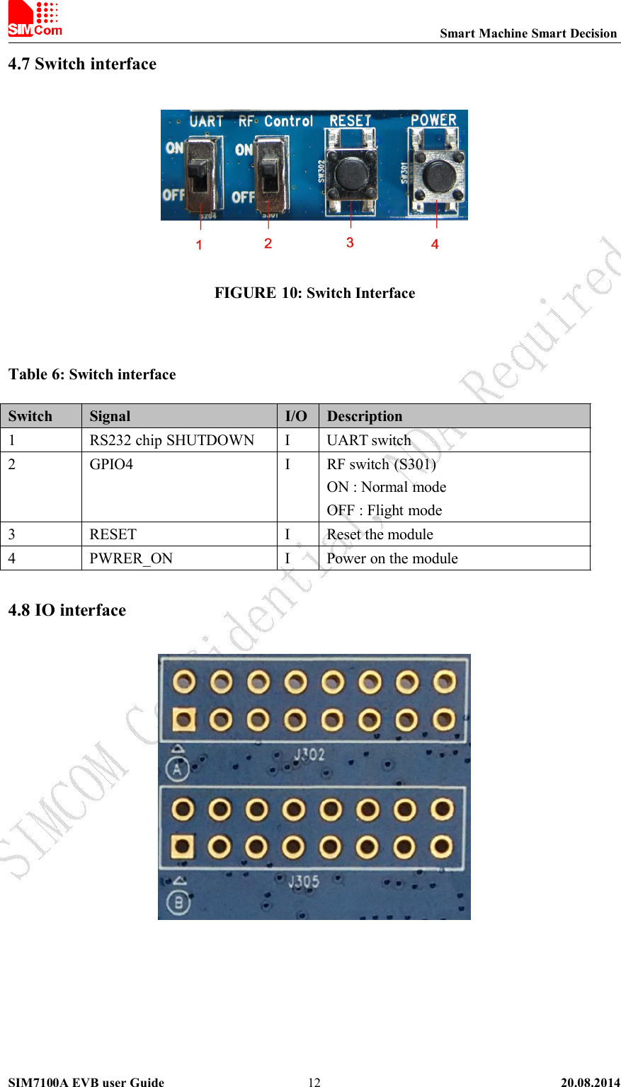
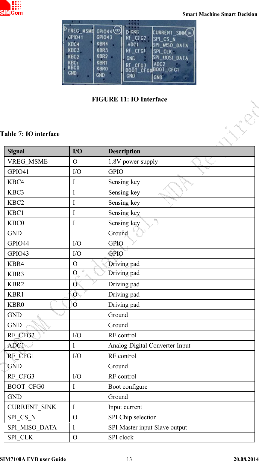
UDV-SIM7100A_EVB_User Guide