Simoco EMEA SDB680UW01 Landmobile UHF Base Station User Manual
Simoco EMEA Ltd Landmobile UHF Base Station
UserManual.wiki
>
Simoco EMEA
>
SDB680UW01 User Manual
User Manual
Navigation menu
Upload a User Manual
Namespaces
Wiki Guide
HTML
PDF
Info
Views
User Manual
Discussion / Help
Navigation


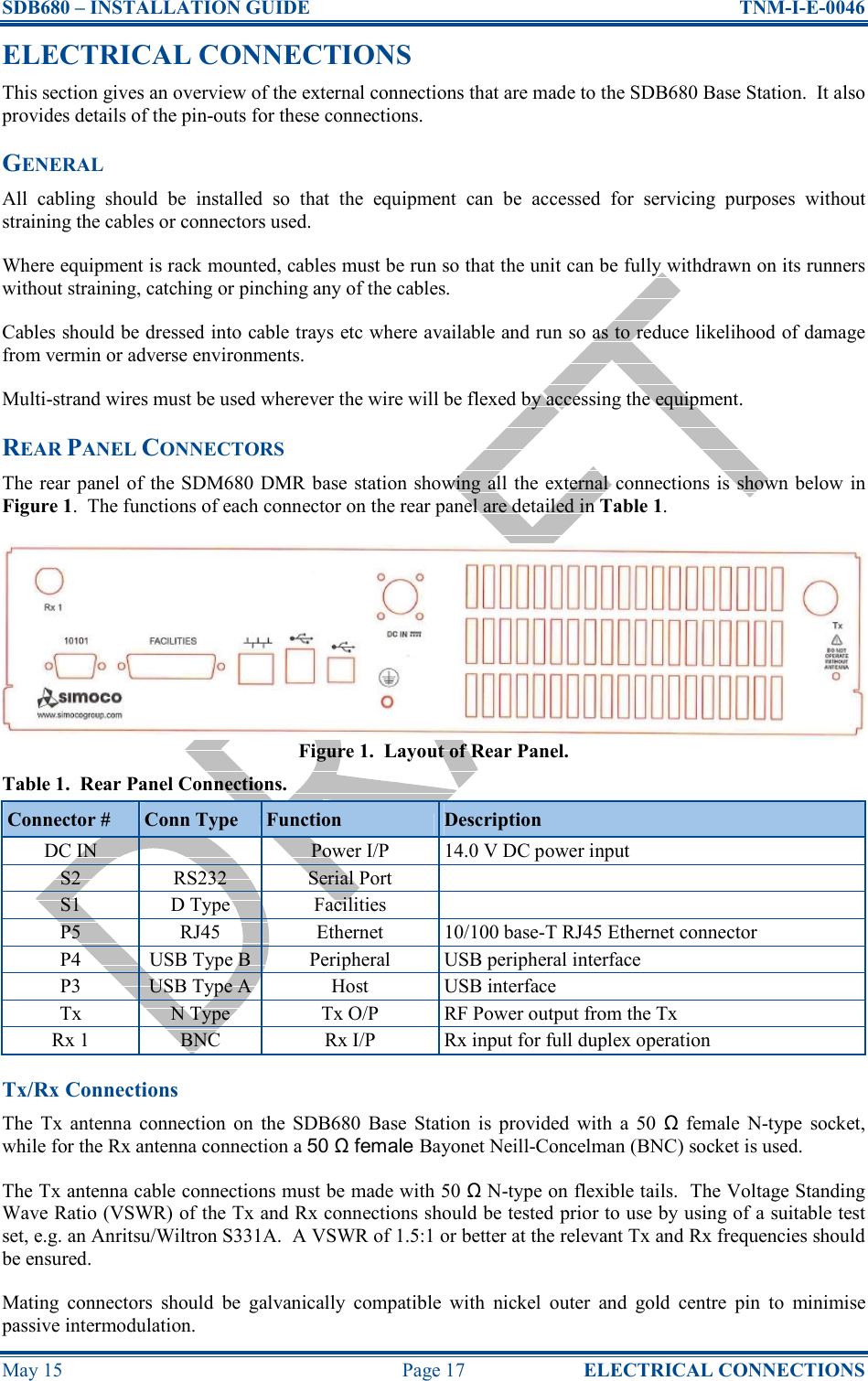
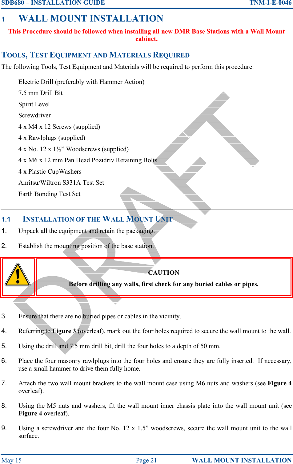
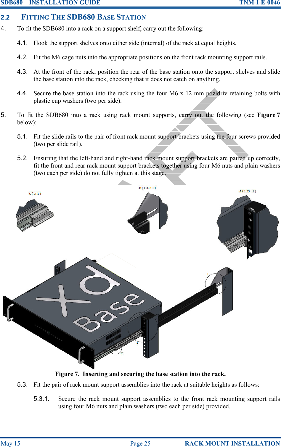
![SDB680 – INSTALLATION GUIDE TNM-I-E-0046 May 15 Page 27 CONFIGURATION TIER II BASE 3 CONFIGURATION OF NEW TIER II BASE STATION This Procedure should be followed when configuring all new Tier II SDB680 Base Stations after their initial installation in a new system. TOOLS, TEST EQUIPMENT AND MATERIALS REQUIRED The following Tools, Test Equipment and Materials will be required to perform this procedure: Dummy Load Personal Computer Software Applications: Simoco Digital Management Terminal (SDMT) Simoco IP Configuration Tool Notes (i). The software applications listed above are available for download on the Simoco website http://www.simocogroup.com via the Partner Portal. To access the Partner Portal a Username and Password will be required. (ii). To request access to the partner portal please contact your local business development manager or alternatively contact the relevant Simoco Customer Services (see Support Page for details). 3.1 SDB680 PREPARATION WARNING RF RADIATION. A RF RADIATION HAZARD EXISTS IN THIS EQUIPMENT. TO AVOID RF INJURY, DO NOT TOUCH THE ANTENNA WHEN THE TRANSMITTER IS IN USE. DO NOT OPERATE TRANSMITTER WITH ANTENNA DISCONNECTED. REFER TO EU DIRECTIVE 2004/40/EC DATED 29 APRIL 2004. 1. Ensure that the SDB680 base stations are securely fitted into the rack and that the power and antenna cables are connected on the rear panel. 2. On the SDB680 rear panel, connect the Tx antenna socket to a suitable dummy load (for the 50 W base a minimum 60 Watt load can be used provided that it is suitable for use). 3. Connect an Ethernet switch cable to the Ethernet socket. 4. Switch on the power for the system and, in turn, power up each SDB680 base station. 3.2 SDMT INSTALLATION AND PREPARATION 5. Refer to the SDMT DMR Tier II User Manual [2] and carry out the following: 5.1. Install the SDMT software in accordance with Section 1.2 – Software Installation. 5.2. Prepare the SDMT software for use in accordance with Section 2.2 – SDMT Preparation. 5.3. Create or establish a connection to a suitable Microsoft SQL Server database in accordance with Section 2.3 – Database Connection.](https://usermanual.wiki/Simoco-EMEA/SDB680UW01/User-Guide-2637722-Page-27.png)
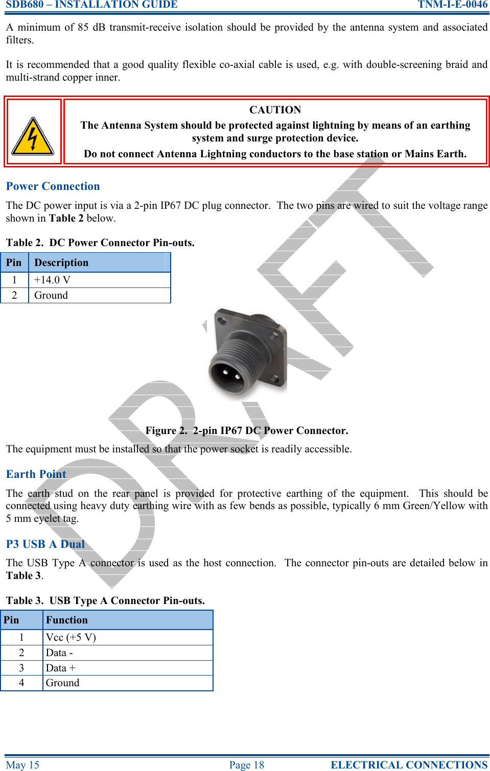
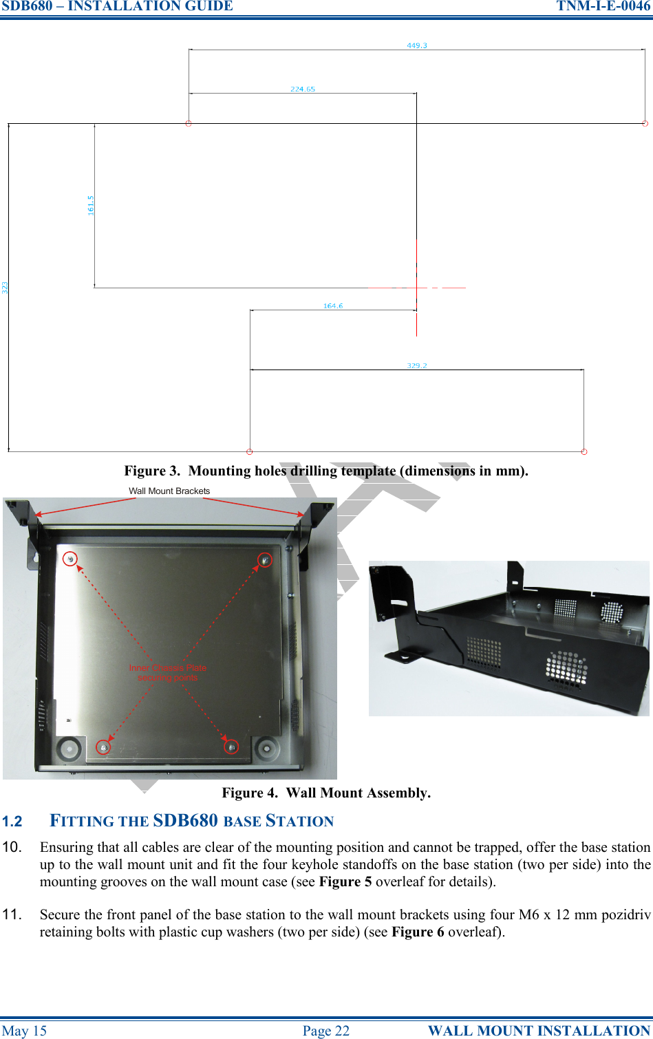
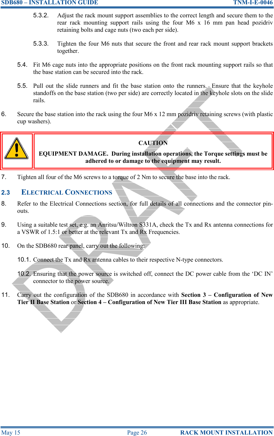
![SDB680 – INSTALLATION GUIDE TNM-I-E-0046 May 15 Page 28 CONFIGURATION TIER II BASE 3.3 INSTALLING THE SIMOCO IP CONFIGURATION SERVER 6. Refer to the Simoco IP Configuration Tool User Manual [3] and install the Simoco IP Configuration Server software in accordance with Section 1.3 – Software Installation. 7. After installing the Simoco IP Configuration Tool software, ensure that the PC on which the software is installed is connected to the Ethernet switch via a CAT 5 Ethernet cable. 3.4 IP ADDRESS CONFIGURATION 8. On the PC, start the Simoco IP Configuration Tool. 9. If the PC has more than one IP address or Network Connection, when the IP Configuration Tool is started, the Interface Selection screen will be displayed (see Figure 8 below). Figure 8. Interface Selection screen. 10. On the Interface Selection screen, select the relevant IP address that is to be used for communicating with the base station(s). 11. Once the IP address has been selected the Simoco IP Configuration Tool main screen will be displayed (see Figure 9 below). Figure 9. IP Configuration Tool main screen 12. Refer to the Simoco IP Configuration Tool User Manual [3] and configure the IP Address for the relevant MAC Address listed in the data grid of the main screen in accordance with Section 2.2 – Configuring an IP Address. 3.5 CONFIGURING THE DMR BASE 13. On the SDMT main screen, carry out the following: 13.1. On the ribbon bar, select the ‘DMR Tier II’ tab.](https://usermanual.wiki/Simoco-EMEA/SDB680UW01/User-Guide-2637722-Page-28.png)
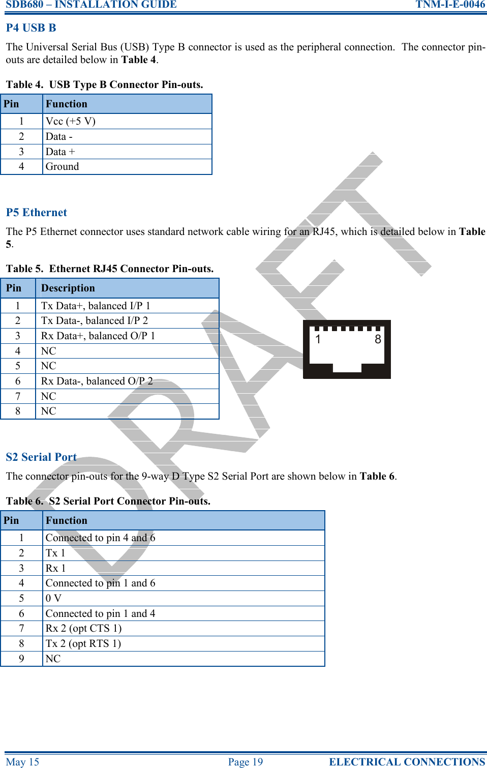
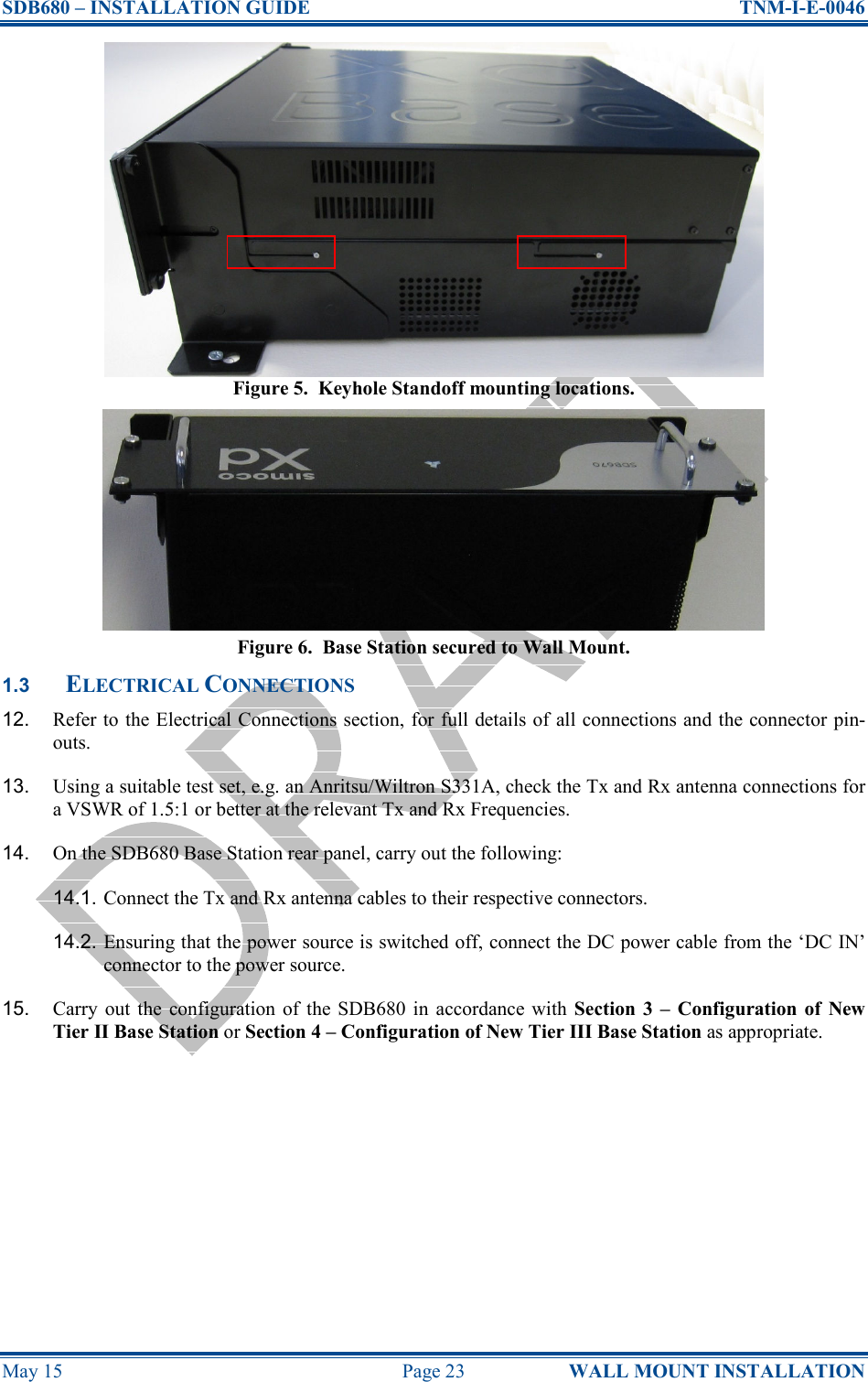
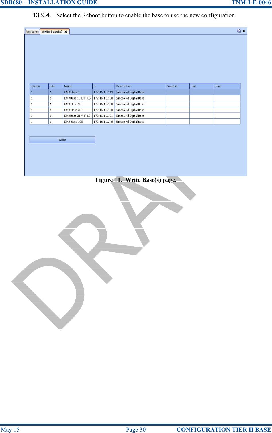
![SDB680 – INSTALLATION GUIDE TNM-I-E-0046 May 15 Page 29 CONFIGURATION TIER II BASE 13.2. On the Site View tab of the Navigation Pane, from the navigation tree, click on the ‘System’ branch to expand it. Click on the ‘Site 1’ node displayed. 13.3. On the Ribbon bar, select the ‘Add Digital Base’ button to add a digital base to Site 1 on the navigation tree. 13.4. On the Site View tab of the Navigation Pane, from the navigation tree, select the new DMR Base that has just been added to the navigation tree. The Base configuration page will be displayed in the configuration page area (see Figure 10 below). Figure 10. Base configuration page – Base Settings tab. 13.5. On the base Configuration page on the Base Settings tab, set the ‘IP Address’ to that sent to the base with the IP Configuration tool. 13.6. On the tab of the base configuration page, select the icon that is displayed to save the changes that have been made to the configuration page. 13.7. Create a working configuration that includes the new DMR Base in accordance with the SDMT User Manual [2] and appropriate for the system in which it is installed. 13.8. On the DMR Tier II ribbon bar, select the ‘Write’ button. The ‘Write Base(s)’ page will be displayed (see Figure 11 overleaf) and any open base configuration pages will be closed. 13.9. On the ‘Write Base(s)’ page, carry out the following: 13.9.1. Select the new DMR Base that is included in the working configuration. 13.9.2. Select the ‘Write’ button. A progress bar will briefly be displayed. 13.9.3. After a few seconds, check that a green dot appears in the Success column for the selected base (indicating that the Write operation has been successful) and a ‘Reboot’ button appears at the bottom of the page. Note. To complete the software configuration update procedure for the selected DMR Base, the base must be re-booted.](https://usermanual.wiki/Simoco-EMEA/SDB680UW01/User-Guide-2637722-Page-29.png)
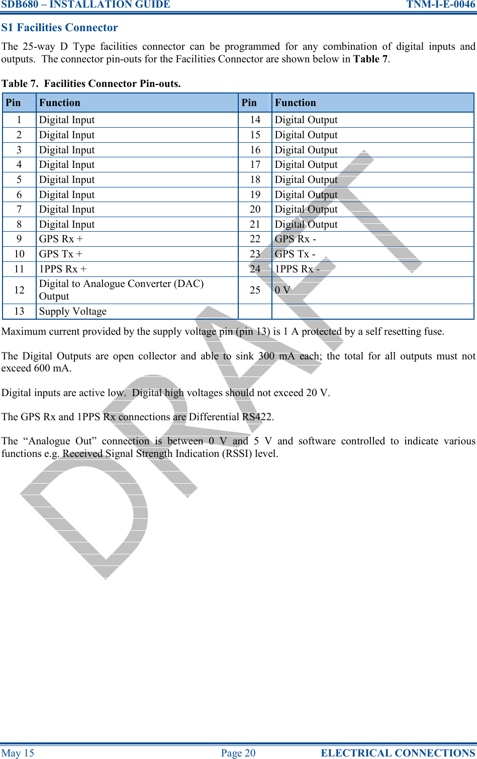
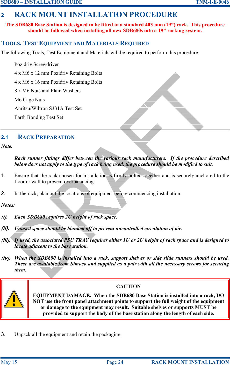
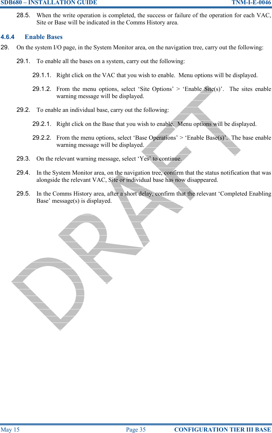
![SDB680 – INSTALLATION GUIDE TNM-I-E-0046 May 15 Page 31 CONFIGURATION TIER III BASE 4 CONFIGURATION OF NEW TIER III BASE STATION This Procedure should be followed when configuring all new Tier III SDB680 Base Stations after their initial installation in a new system. TOOLS, TEST EQUIPMENT AND MATERIALS REQUIRED The following Tools, Test Equipment and Materials will be required to perform this procedure: Dummy Load Personal Computer Software Applications: SDMT Simoco IP Configuration Tool Notes (i). The software applications listed above are available for download on the Simoco website http://www.simocogroup.com via the Partner Portal. To access the Partner Portal a Username and Password will be required. (ii). To request access to the partner portal please contact your local business development manager or alternatively contact the relevant Simoco Customer Services (see Support Page for details). 4.1 SOFTWARE LICENCES All Tier III Base Stations require a Software Licence in order to operate; these licences can be obtained from Simoco. If a Tier III Base Station is added to an existing Tier III system, the software licences for all the base stations on that system will have to be updated. It is assumed that all the relevant software licences required have been obtained before commencing this procedure and that they have been uploaded onto a suitable PC. 4.2 SDB680 PREPARATION WARNING RF RADIATION. A RF RADIATION HAZARD EXISTS IN THIS EQUIPMENT. TO AVOID RF INJURY, DO NOT TOUCH THE ANTENNA WHEN THE TRANSMITTER IS IN USE. DO NOT OPERATE TRANSMITTER WITH ANTENNA DISCONNECTED. REFER TO EU DIRECTIVE 2004/40/EC DATED 29 APRIL 2004. 1. Ensure that the SDB680 base stations are securely fitted into the rack and that the power and antenna cables are connected on the rear panel. 2. On the SDB680 rear panel, connect the Tx antenna socket to a suitable dummy load (for the 50 W base a minimum 60 Watt load can be used provided that it is suitable for use). 3. Connect an Ethernet switch cable to the Ethernet socket. 4. Switch on the power for the system and, in turn, power up each SDB680 base station. 4.3 SDMT INSTALLATION AND PREPARATION 5. Refer to the SDMT User Manual [2] and carry out the following:](https://usermanual.wiki/Simoco-EMEA/SDB680UW01/User-Guide-2637722-Page-31.png)
![SDB680 – INSTALLATION GUIDE TNM-I-E-0046 May 15 Page 32 CONFIGURATION TIER III BASE 5.1. Install the SDMT software in accordance with Section 1.2 – Software Installation. 5.2. Prepare the SDMT software for use in accordance with Section 2.2 – SDMT Preparation. 5.3. Create or establish a connection to a suitable Microsoft SQL Server database in accordance with Section 2.2.3 – Database Connection. 4.4 INSTALLING THE SIMOCO IP CONFIGURATION SERVER 6. Refer to the Simoco IP Configuration Tool User Manual [3] and install the Simoco IP Configuration Server software in accordance with Section 1.3 – Software Installation. 7. After installing the Simoco IP Configuration Tool software, ensure that the PC on which the software is installed is connected to the Ethernet switch via a CAT 5 Ethernet cable. 4.5 IP ADDRESS CONFIGURATION 8. On the PC, start the Simoco IP Configuration Tool. 9. If the PC has more than one IP address or Network Connection, when the IP Configuration Tool is started, the Interface Selection screen will be displayed (see Figure 12 below). Figure 12. Interface Selection screen. 10. On the Interface Selection screen, select the relevant IP address that is to be used for communicating with the base station(s). 11. Once the IP address has been selected the Simoco IP Configuration Tool main screen will be displayed (see Figure 13 below). Figure 13. IP Configuration Tool main screen](https://usermanual.wiki/Simoco-EMEA/SDB680UW01/User-Guide-2637722-Page-32.png)
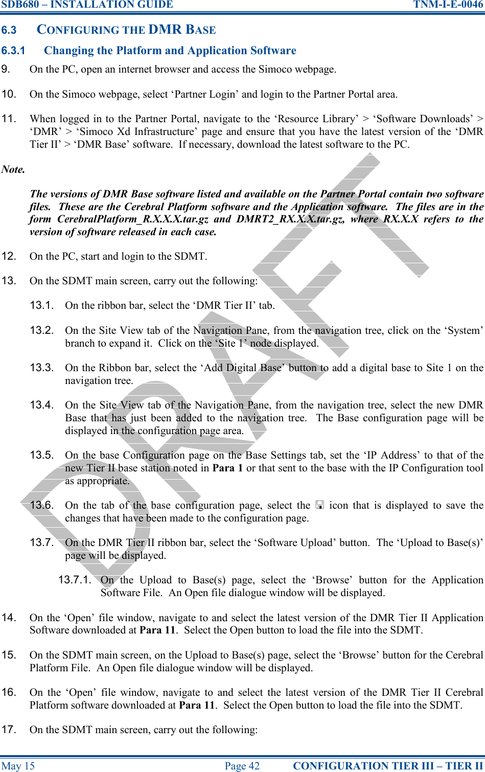
![SDB680 – INSTALLATION GUIDE TNM-I-E-0046 May 15 Page 33 CONFIGURATION TIER III BASE 12. Refer to the Simoco IP Configuration Tool User Manual [3] and configure the IP Address for the relevant MAC Address listed in the data grid of the main screen in accordance with Section 2.2 – Configuring an IP Address. 4.6 CONFIGURING THE DMR BASE 4.6.1 Platform and Application Software Update 13. On the PC, open an internet browser and access the Simoco webpage. 14. On the Simoco webpage, select ‘Partner Login’ and login to the Partner Portal area. 15. When logged in to the Partner Portal, navigate to the ‘Resource Library’ > ‘Software Downloads’ > ‘DMR’ > ‘Simoco Xd Infrastructure’ page and ensure that you have the latest version of the ‘DMR Tier III’ > ‘DMR Base’ software. If necessary, download the latest software to the PC. Note. The versions of DMR Base software listed and available on the Partner Portal contain two software files. These are the Cerebral Platform software and the Application software. The files are in the form CerebralPlatform_R.X.X.X.tar.gz and DMRT3_RX.X.X.tar.gz, where RX.X.X refers to the version of software released in each case. 16. On the PC, start and login to the SDMT. The System Selector screen will be displayed. 17. On the ‘System Selector’ screen, carry out either of the following: 17.1. If the base station is to be added to an existing Tier III system, select the system number from the displayed list and select the ‘OK’ button. 17.2. If the base station is to be added to a new Tier III system, enter the system number for the new system and select the ‘OK’ button. Note. The Tier III system number selected or entered above must match that entered when configuring the IP address for the Tier III base station. Refer to Para 12 above and Para 2.3 of Section 2.2 – Configuring an IP Address in the Simoco IP Configuration Tool User Manual [3] for clarification. 18. On the SDMT main screen, carry out the following: 18.1. On the ribbon bar, select the DMR Tier III tab. 18.2. On the DMR Tier III ribbon bar, select the System Commands button. The System I/O page will be displayed. 18.3. On the System I/O page, select the ‘Browse’ button for relevant software you wish to upload (i.e. Cerebral Platform or Application Software). An open file dialogue window will be displayed. 19. On the ‘Open’ file window, navigate to and select the latest version of DMR Tier III software (i.e. Cerebral Platform or Application Software) downloaded at Para 15. Select the Open button to load the file into the SDMT. 20. Repeat Para 18.3 and Para 19 for the other type of software (i.e. Cerebral Platform or Application Software) as required. 21. On the SDMT, on the System I/O Page, carry out the following:](https://usermanual.wiki/Simoco-EMEA/SDB680UW01/User-Guide-2637722-Page-33.png)
![SDB680 – INSTALLATION GUIDE TNM-I-E-0046 May 15 Page 34 CONFIGURATION TIER III BASE 21.1. In the System Monitor area, on the navigation tree, right click on the Base that you wish to upload the software to. Menu options will be displayed. 21.2. From the menu options, select ‘Update’ > ‘Update Software’. 21.3. In the Comms History area, confirm that a ‘Starting Update Software’ message is displayed. 21.4. The progress of the software update operation will be displayed in the ‘Current Message Progress’ area. 21.5. In the Comms History area, after a short delay, confirm that a ‘Completed Update Software’ message is displayed. 4.6.2 Software Licence Update 22. On the SDMT, on the System I/O Page, select the ‘Browse’ button for the Licence file. An Open file dialogue window will be displayed. 23. On the ‘Open’ file window, navigate to and select the relevant software licence file. Select the Open button to load the file into the SDMT. 24. On the SDMT main screen, on the System I/O page, carry out the following: 24.1. In the System Monitor area, on the navigation tree, right click on the VAC for the system. Menu options will be displayed. 24.2. From the VAC menu options, select ‘Update’ > ‘Update Software’. 24.3. In the Comms History area, confirm that a ‘Starting Update Software’ message is displayed. 24.4. The progress of the update operation will be displayed in the ‘Current Message Progress’ area. 24.5. In the Comms History area, after a short delay, confirm that a ‘Completed Update Software’ message is displayed. 4.6.3 Configuration Creation and Upload 25. Refer to Part 3 of the SDMT User Manual [2] and create a working configuration that includes the new DMR Base and appropriate for the system in which it is installed. 26. When creating a working configuration, ensure that any changes to the configuration are saved by selecting the icon that will be displayed on the page tab of the relevant configuration pages. This will save the changes to the local SQL Server ® database stored on the PC. 27. On the SDMT main screen, on the ribbon bar, select the System Commands button. The System I/O configuration page will be displayed. 28. On the System I/O page, carry out the following: 28.1. In the ‘Select Read/Write System Areas’ box, depending on the configuration you wish to write, select either the ‘Configuration’, the ‘Subscribers’ or both. Select the ‘Write to System’ button. 28.2. In the Comms History area, confirm that a ‘Starting Write All Config’ message is displayed. 28.3. The progress of the write operation will be displayed in the ‘Current Message Progress’ area. 28.4. In the Comms History area, after a short delay, confirm that a ‘Completed Write All Config’ message is displayed.](https://usermanual.wiki/Simoco-EMEA/SDB680UW01/User-Guide-2637722-Page-34.png)
![SDB680 – INSTALLATION GUIDE TNM-I-E-0046 May 15 Page 37 CONFIGURATION TIER II – TIER III 7. Refer to the Simoco IP Configuration Tool User Manual [3] and configure a Tier II IP Address for the relevant MAC Address listed in the data grid of the main screen in accordance with Section 2.2 – Configuring an IP Address. 5.4 CONFIGURING THE DMR BASE 5.4.1 Platform and Application Software Update 8. On the PC, open an internet browser and access the Simoco webpage. 9. On the Simoco webpage, select ‘Partner Login’ and login to the Partner Portal area. 10. When logged in to the Partner Portal, navigate to the ‘Resource Library’ > ‘Software Downloads’ > ‘DMR’ > ‘Simoco Xd Infrastructure’ page and ensure that you have the latest version of the ‘DMR Tier III’ > ‘DMR Base’ software. If necessary, download the latest software to the PC. Note. The versions of DMR Base software listed and available on the Partner Portal contain two software files. These are the Cerebral Platform software and the Application software. The files are in the form CerebralPlatform_R.X.X.X.tar.gz and DMRT3_RX.X.X.tar.gz, where RX.X.X refers to the version of software released in each case. 11. On the PC, start and login to the SDMT. The System Selector screen will be displayed. 12. On the ‘System Selector’ screen, carry out either of the following: 12.1. If the base station is to be added to an existing Tier III system, select the system number from the displayed and select the ‘OK’ button. 12.2. If the base station is to be added to a new Tier III system, enter the system number for the new system and select the ‘OK’ button. 13. On the SDMT main screen, carry out the following: 13.1. On the ribbon bar, select the DMR Tier II tab. 13.2. On the Site View tab of the Navigation Pane, from the navigation tree, click on the ‘System’ branch to expand it. Click on the ‘Site 1’ node displayed. 13.3. On the DMR Tier II ribbon bar, select the ‘Add Digital Base’ button to add a digital base to Site 1 on the navigation tree. 13.4. On the Site View tab of the Navigation Pane, from the navigation tree, select the new DMR Base that has just been added to the navigation tree. The Base configuration page will be displayed in the configuration page area. 13.5. On the base Configuration page on the Base Settings tab, set the ‘IP Address’ to that of the new Tier III base station noted in Para 1 or that sent to the base with the IP Configuration tool as appropriate. 13.6. On the tab of the base configuration page, select the icon that is displayed to save the changes that have been made to the configuration page. 13.7. On the DMR Tier II ribbon bar, select the ‘Software Upload’ button. The ‘Upload to Base(s)’ page will be displayed. 13.7.1. On the Upload to Base(s) page, select the ‘Browse’ button for the Application Software File. An Open file dialogue window will be displayed.](https://usermanual.wiki/Simoco-EMEA/SDB680UW01/User-Guide-2637722-Page-37.png)
![SDB680 – INSTALLATION GUIDE TNM-I-E-0046 May 15 Page 38 CONFIGURATION TIER II – TIER III 14. On the ‘Open’ file window, navigate to and select the latest version of the DMR Tier III Application Software downloaded at Para 10. Select the Open button to load the file into the SDMT. 15. On the SDMT main screen, on the Upload to Base(s) page, select the ‘Browse’ button for the Cerebral Platform File. An Open file dialogue window will be displayed. 16. On the ‘Open’ file window, navigate to and select the latest version of the DMR Tier III Cerebral Platform software downloaded at Para 10. Select the Open button to load the file into the SDMT. 17. On the SDMT main screen, carry out the following: 17.1. On the Upload to Base(s) page, carry out the following: 17.1.1. Select the base(s) you wish to upload the software to. 17.1.2. Select the ‘Upload’ button to programme the base with the Application Software and the Cerebral Platform. 17.2. On the DMR Tier II ribbon bar, select the Re-boot button. The Re-boot Base(s) page will be displayed. 17.3. On the Re-boot Base(s) page, select the base station(s) that the software was uploaded to and select the ‘Re-boot’ button. The base station(s) will re-boot and load the new versions of software. 5.4.2 Tier III IP Address Configuration 18. On the IP Configuration Tool, in the data grid of the main screen, select the relevant MAC Address for the Tier II Base. 19. Refer to the Simoco IP Configuration Tool User Manual [3] and configure a Tier III IP Address for the relevant MAC Address listed in the data grid of the main screen in accordance with Section 2.2 – Configuring an IP Address. Ensure that the ‘System’, ‘VAC’, ‘Site’ and ‘Base’ details entered are relevant to the Tier III system. Note. When configuring the IP address for the Tier III base station, the Tier III ‘System’ number entered above must match the system number that the Tier III base station is to be added to. Refer to Para 12 above and Para 2.3 of Section 2.2 – Configuring an IP Address in the Simoco IP Configuration Tool User Manual [3] for clarification. 5.4.3 Software Licence Update 20. On the SDMT main screen, on the ribbon bar, select the DMR Tier III tab. 20.1. On the DMR Tier III ribbon bar, select the System Commands button. The System I/O configuration page will be displayed. 20.2. On the System I/O page, in the System Monitor area, expand the navigation tree and check that the new Tier III base has been added to the system. 20.3. On the System I/O page, select the ‘Browse’ button for the Licence file. An Open file dialogue window will be displayed. 21. On the ‘Open’ file window, navigate to and select the relevant software licence file. Select the Open button to load the file into the SDMT. 22. On the SDMT main screen, on the System I/O page, carry out the following:](https://usermanual.wiki/Simoco-EMEA/SDB680UW01/User-Guide-2637722-Page-38.png)
![SDB680 – INSTALLATION GUIDE TNM-I-E-0046 May 15 Page 39 CONFIGURATION TIER II – TIER III 22.1. In the System Monitor area, on the navigation tree, right click on the VAC for the system. Menu options will be displayed. 22.2. From the VAC menu options, select ‘Update’ > ‘Update Software’. 22.3. In the Comms History area, confirm that a ‘Starting Update Software’ message is displayed. 22.4. The progress of the update operation will be displayed in the ‘Current Message Progress’ area. 22.5. In the Comms History area, after a short delay, confirm that a ‘Completed Update Software’ message is displayed. 22.6. In the System Monitor area, on the navigation tree, right click on the VAC for the system. Menu options will be displayed. 22.7. From the VAC menu options, select ‘Base Operations’ > ‘Reboot Base(s)’. The Reboot Base(s) warning message will be displayed. 22.8. On the Reboot Base(s) warning message, select ‘Yes’ to continue. 22.9. In the Comms History area, after a short delay, confirm that a ‘Resetting VAC’ message is displayed. 22.10. In the Comms History area, various messages for the reboot operation will be displayed. Eventually, as the reboot of each base station in the Tier III system is completed, an appropriate ‘Discovered Base’ message will be displayed. 5.4.4 Configuration Creation and Upload 23. On the SDMT main screen, carry out the following: 23.1. Refer to Part 3 of the SDMT User Manual [2] and create a working configuration that includes the new DMR Base and appropriate for the system in which it is installed. 23.2. When creating a working configuration, ensure that any changes to the configuration are saved by selecting the icon that will be displayed on the page tab of the relevant configuration pages. This will save the changes to the local SQL Server ® database stored on the PC. 23.3. On the ribbon bar, select the System Commands button. The System I/O configuration page will be displayed. 23.4. On the System I/O page, carry out the following: 23.4.1. In the ‘Select Read/Write System Areas’ box, depending on the configuration you wish to write, select either the ‘Configuration’, the ‘Subscribers’ or both. Select the ‘Write to System’ button. 23.4.2. In the Comms History area, confirm that a ‘Starting Write All Config’ message is displayed. 23.4.3. The progress of the write operation will be displayed in the ‘Current Message Progress’ area. 23.4.4. In the Comms History area, after a short delay, confirm that a ‘Completed Write All Config’ message is displayed. 23.4.5. When the write operation is completed, the success or failure of the operation for each VAC, Site or Base will be indicated in the Comms History area.](https://usermanual.wiki/Simoco-EMEA/SDB680UW01/User-Guide-2637722-Page-39.png)

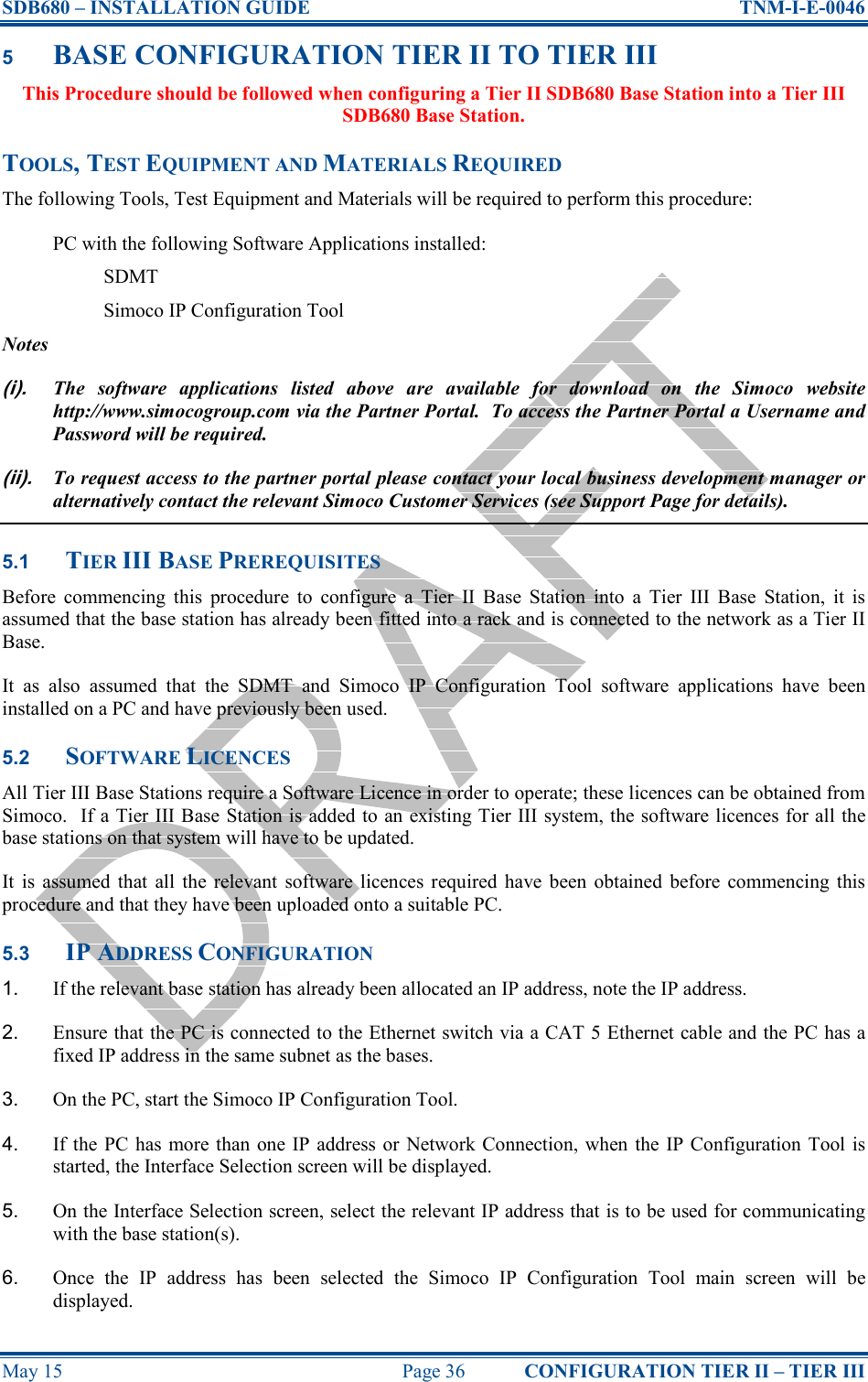
![SDB680 – INSTALLATION GUIDE TNM-I-E-0046 May 15 Page 41 CONFIGURATION TIER III – TIER II 6 BASE CONFIGURATION TIER III TO TIER II This Procedure should be followed when configuring a Tier III Base Station into a Tier II SDB680 Base Station. TOOLS, TEST EQUIPMENT AND MATERIALS REQUIRED The following Tools, Test Equipment and Materials will be required to perform this procedure: PC with the following Software Applications installed: SDMT Simoco IP Configuration Tool Notes (i). The software applications listed above are available for download on the Simoco website http://www.simocogroup.com via the Partner Portal. To access the Partner Portal a Username and Password will be required. (ii). To request access to the partner portal please contact your local business development manager or alternatively contact the relevant Simoco Customer Services (see Support Page for details). 6.1 TIER II BASE PREREQUISITES Before commencing this procedure to configure a Tier III Base Station into a Tier II Base Station, it is assumed that the base station has already been fitted into a rack and is connected to the relevant system. It as also assumed that the SDMT and Simoco IP Configuration Tool software applications have been installed on a PC and have previously been used. 6.2 IP ADDRESS CONFIGURATION 1. If the relevant base station has already been allocated an IP address, note the IP address. 2. If the relevant base station has not been allocated an IP address, carry out the IP address configuration as described below. 3. Ensure that the PC is connected to the Ethernet switch via a CAT 5 Ethernet cable and the PC has a fixed IP address in the same subnet as the bases. 4. On the PC, start the Simoco IP Configuration Tool. 5. If the PC has more than one IP address or Network Connection, when the IP Configuration Tool is started, the Interface Selection screen will be displayed. 6. On the Interface Selection screen, select the relevant IP address that is to be used for communicating with the base station(s). 7. Once the IP address has been selected the Simoco IP Configuration Tool main screen will be displayed. 8. Refer to the Simoco IP Configuration Tool User Manual [3] and configure the IP Address for the relevant MAC Address listed in the data grid of the main screen in accordance with Section 2.2 – Configuring an IP Address.](https://usermanual.wiki/Simoco-EMEA/SDB680UW01/User-Guide-2637722-Page-41.png)
![SDB680 – INSTALLATION GUIDE TNM-I-E-0046 May 15 Page 43 CONFIGURATION TIER III – TIER II 17.1. On the Upload to Base(s) page, carry out the following: 17.1.1. Select the base you wish to upload the software to. 17.1.2. Select the ‘Upload’ button to programme the base with the Application Software and the Cerebral Platform. 17.2. On the DMR Tier II ribbon bar, select the Re-boot button. The Re-boot Base(s) page will be displayed. 17.3. On the Re-boot Base(s) page, select the base station that the software was uploaded to and select the ‘Re-boot’ button. The base station will re-boot and load the new versions of software. 17.4. Create a working configuration that includes the new DMR Base in accordance with the SDMT User Manual [2] and appropriate for the system in which it is installed. 17.5. On the DMR Tier II ribbon bar, select the ‘Write’ button. The ‘Write Base(s)’ page will be displayed and any open base configuration pages will be closed. 17.6. On the ‘Write Base(s)’ page, carry out the following: 17.6.1. Select the new DMR Base that is included in the working configuration. 17.6.2. Select the ‘Write’ button. A progress bar will briefly be displayed. 17.6.3. After a few seconds, check that a green dot appears in the Success column for the selected base (indicating that the Write operation has been successful) and a ‘Reboot’ button appears at the bottom of the page. Note. To complete the software configuration update procedure for the selected DMR Base, the base must be re-booted. 17.6.4. Select the Reboot button to enable the base to use the new configuration.](https://usermanual.wiki/Simoco-EMEA/SDB680UW01/User-Guide-2637722-Page-43.png)