Simoco EMEA SDB680UW01 Landmobile UHF Base Station User Manual
Simoco EMEA Ltd Landmobile UHF Base Station
User Manual

SDB680 BASE STATION
INSTALLATION GUIDE
TNM-I-E-0046, Issue 1.1 Draft
May 2015
Field House,
Uttoxeter Old Road
Derby
DE1 1NH
Tel: +44 (0) 1332 375500
FAX: +44 (0) 1332 375501
http://www.simocogroup.com
1270 Ferntree Gully Road,
Scoresby
Victoria, 3179
Australia
Tel: +61 (0)3 9730 3999
FAX: +61 (0)3 9730 3988
http://www.simocogroup.com
©Simoco 2014

SDB680 – INSTALLATION GUIDE TNM-I-E-0046
May 15 Page 2 PREFACE
PREFACE
Before installation, commissioning or operation, this document should be read in full.
In particular, the following parts MUST be read:
• Appendix A – Simoco Digital Management Terminal (SDMT) Getting Started
Information.
D
ECLARATION
This Installation Guide covers the SDB680 50 W Base Station for installation in Wall Mount and Rack
Mount variants.
Any performance figures quoted are subject to normal manufacturing and service tolerances. The right is
reserved to alter the equipment described in this manual in the light of future technical development.
Changes or modifications not expressly approved by the party responsible for compliance could void the
user’s authority to operate the equipment.
C
OPYRIGHT
All information contained in this document is the property of Simoco. All rights are reserved. This
document may not, in whole or in part, be copied, photocopied, reproduced, translated, stored, or reduced to
any electronic medium or machine-readable form, without prior written permission from Simoco.
C
OMPUTER
S
OFTWARE
C
OPYRIGHTS
The AMBE+2TM voice coding Technology embodied in this product is protected by intellectual property
rights including patent rights, copyrights and trade secrets of Digital Voice Systems, Inc. This voice coding
Technology is licensed solely for use within this Communications Equipment. The user of this Technology
is explicitly prohibited from attempting to extract, remove, decompile, reverse engineer, or disassemble the
Object Code, or in any other way convert the Object Code into a human-readable form. U.S. Patent Nos.
#6,912,495 B2, #6,199,037 B1, #5,870,405, #5,826,222, #5,754,974, #5,701,390, #5,715,365, #5,649,050,
#5,630,011, #5,581,656, #5,517,511, #5,491,772, #5,247,579, #5,226,084 and #5,195,166.
D
ISCLAIMER
There are no warranties extended or granted by this document. Simoco accepts no responsibility for damage
arising from use of the information contained in the document or of the equipment and software it describes.
It is the responsibility of the user to ensure that use of such information, equipment and software complies
with the laws, rules and regulations of the applicable jurisdictions.
E
QUIPMENT AND
M
ANUAL
U
PDATES
In the interests of improving the performance, reliability or servicing of the equipment, Simoco reserves the
right to update the equipment or this document or both without prior notice.
E
RRORS AND
O
MISSIONS
The usefulness of this publication depends upon the accuracy and completeness of the information contained
within it. Whilst every endeavour has been made to eliminate any errors, some may still exist. It is
requested that any errors or omissions noted should be reported to either of the following who are part of the
Simoco group:

SDB680 – INSTALLATION GUIDE TNM-I-E-0046
May 15 Page 3 PREFACE
Field House
Uttoxeter Old Road, Derby.
DE1 1NH. UK
1270 Ferntree Gully Road, Scoresby
Victoria. 3179
Australia
Tel: +44 (0) 871 741 1050 Tel: +61 (0)3 9730 3999
E-mail: customer.service@simocogroup.com E-mail: inquiry.aus@simocogroup.com
D
OCUMENT
H
ISTORY
Issue Date Comments
1.0 August 2014 Initial Issue.
R
ELATED
D
OCUMENTS
1. TNM-M-E-0047. SDB680 Base Station – Service Manual.
2. TNM-U-E-0112. Simoco Digital Management Terminal – User Manual.
3. TNM-U-E-0120. Simoco IP Configuration Tool – User Manual.
To order printed copies of this or any of the above publications, please contact Simoco. See the Support
page for contact information.
A comprehensive list of documentation is available for download on the Simoco website
http://www.simocogroup.com via the Partner Portal.

SDB680 – INSTALLATION GUIDE TNM-I-E-0046
May 15 Page 4 CONTENTS
TABLE OF CONTENTS
Page
Title Page ......................................................................................................................................................... 1
Preface .............................................................................................................................................................. 2
Table of Contents (This List) ......................................................................................................................... 4
List of Figures .................................................................................................................................................. 5
List of Tables ................................................................................................................................................... 5
Personal Safety ................................................................................................................................................ 6
Equipment Safety ............................................................................................................................................ 7
WEEE Notice ................................................................................................................................................... 9
Support .......................................................................................................................................................... 10
Abbreviations ................................................................................................................................................ 12
RECOMMENDED TOOLS, TEST EQUIPMENT AND MATERIALS ................................................ 13
ENVIRONMENTAL CONDITIONS ......................................................................................................... 14
MOUNTING LOCATION ........................................................................................................................... 15
POWER SUPPLIES ..................................................................................................................................... 16
ELECTRICAL CONNECTIONS ............................................................................................................... 17
PROCEDURES
1
WALL MOUNT INSTALLATION ................................................................................................... 21
2
RACK MOUNT INSTALLATION PROCEDURE ......................................................................... 24
3
CONFIGURATION OF NEW TIER II BASE STATION .............................................................. 27
4
CONFIGURATION OF NEW TIER III BASE STATION ............................................................ 31
5
BASE CONFIGURATION TIER II TO TIER III........................................................................... 36
6
BASE CONFIGURATION TIER III TO TIER II........................................................................... 41

SDB680 – INSTALLATION GUIDE TNM-I-E-0046
May 15 Page 5 CONTENTS
LIST OF FIGURES
Page
Figure 1. Layout of Rear Panel. ...................................................................................................................... 17
Figure 2. 2-pin IP67 DC Power Connector..................................................................................................... 18
Figure 3. Mounting holes drilling template (dimensions in mm). .................................................................. 22
Figure 4. Wall Mount Assembly..................................................................................................................... 22
Figure 5. Keyhole Standoff mounting locations. ............................................................................................ 23
Figure 6. Base Station secured to Wall Mount. .............................................................................................. 23
Figure 7. Inserting and securing the base station into the rack. ...................................................................... 25
Figure 8. Interface Selection screen................................................................................................................ 28
Figure 9. IP Configuration Tool main screen ................................................................................................. 28
Figure 10. Base configuration page – Base Settings tab................................................................................. 29
Figure 11. Write Base(s) page. ....................................................................................................................... 30
Figure 12. Interface Selection screen.............................................................................................................. 32
Figure 13. IP Configuration Tool main screen ............................................................................................... 32
LIST OF TABLES
Page
Table 1. Rear Panel Connections.................................................................................................................... 17
Table 2. DC Power Connector Pin-outs.......................................................................................................... 18
Table 3. Ethernet RJ45 Connector Pin-outs....................................................................................................... i
Table 4. Facilities Connector Pin-outs............................................................................................................ 20
Table 5. S2 Serial Port Connector Pin-outs. ................................................................................................... 19
Table 6. USB Type A Connector Pin-outs...................................................................................................... 18
Table 7. USB Type B Connector Pin-outs...................................................................................................... 19

SDB680 – INSTALLATION GUIDE TNM-I-E-0046
May 15 Page 6 WARNINGS
PERSONAL SAFETY
S
AFETY
P
RECAUTIONS
These Safety Precautions, Warnings and Cautions advise personnel of specific hazards which may be
encountered during the procedures contained in this document and that control measures are required to
prevent injury to personnel, and damage to equipment and/or the environment.
Before commencing the installation or any maintenance of this equipment, personnel are to acquaint
themselves with all risk assessments relevant to the work site and the task. They must then comply with the
control measures detailed in those risk assessments.
References covering safety regulations, health hazards and hazardous substances are detailed under the
WARNINGS section below. These are referred to in the tasks, when encountered.
Adequate precautions must be taken to ensure that other personnel do not activate any equipment that has
been switched off for maintenance. Refer to the relevant Electrical Safety Regulations appropriate to the
country of operation.
Where dangerous voltages are exposed during a task, safety personnel are to be provided as detailed in the
relevant Electrical Safety Regulations. Where safety personnel are required for any other reason,
management are to ensure that the personnel detailed are aware of the hazard and are fully briefed on the
action to be taken in an emergency.
Where equipment contains heavy components or units that require lifting, lowering, pulling or pushing
operations to be performed on them during maintenance tasks, all managers and tradesmen are to be
conversant with the Manual Handling Operations Regulations.
H
AZARDOUS
S
UBSTANCES
Before using any hazardous substance or material, the user must be conversant with the safety precautions
and first aid instructions:
•
On the label of the container in which it was supplied.
•
On the material Safety Data Sheet.
•
In any local Safety Orders and Regulations.
WARNINGS
H
EAVY
E
QUIPMENT
WARNING
HEAVY EQUIPMENT. THE WEIGHT OF A FULLY ASSEMBLED SDB680
BASE STATION IN THE WALL MOUNT IS APPROX 10 KG (2 MEN TO
LIFT). REFER TO THE MANUAL HANDLING OPERATIONS
REGULATIONS 1992.
R
ADIO
F
REQUENCY
R
ADIATION
(EU)
WARNING
RADIO FREQUENCY (RF) RADIATION. A RF RADIATION HAZARD
EXISTS IN THIS EQUIPMENT. TO AVOID RF INJURY, DO NOT TOUCH
THE ANTENNA WHEN THE TRANSMITTER IS IN USE. DO NOT
OPERATE TRANSMITTER WITH ANTENNA DISCONNECTED. REFER
TO EU DIRECTIVE 2004/40/EC DATED 29 APRIL 2004.
SDB680 – INSTALLATION GUIDE TNM-I-E-0046
May 15 Page 7 WARNINGS
H
UMAN
E
XPOSURE TO
R
ADIO
F
REQUENCY
R
ADIATION
(FCC)
WARNING
TO COMPLY WITH THE MAXIMUM PERMISSIBLE EXPOSURE (MPE)
LIMITS REFERENCED IN 47 CFR 1.1310 TABLE 1, THE FOLLOWING
MINIMUM SAFE OPERATING DISTANCES MUST BE OBSERVED:
150 to 174 MHz: 1.8 m
406.1 to 480 MHz: 1.52 m
480 to 512 MHz: 1.49 m
FCC PART 15 C
OMPLIANCE
THIS DEVICE COMPLIES WITH PART 15 OF THE FCC RULES.
OPERATION IS SUBJECT TO THE FOLLOWING TWO CONDITIONS:
(1) THIS DEVICE MAY NOT CAUSE HARMFUL INTERFERENCE, AND
(2) THIS DEVICE MUST ACCEPT ANY INTERFERENCE RECEIVED,
INCLUDING INTERFERENCE THAT MAY CAUSE UNDESIRED
OPERATION.
D
ANGEROUS
V
OLTAGES
Dangerous voltages exist in this equipment, for the appropriate Safety precautions, refer to the relevant
Electrical Safety Regulations appropriate to the country of operation.
EQUIPMENT SAFETY
I
NSTALLATION AND
M
AINTENANCE
The SDB680 Series of base stations should only be installed and maintained by qualified personnel.
C
AUTIONS
CAUTION
Before drilling any walls, first check for any buried cables or pipes.
CAUTION
EQUIPMENT DAMAGE. When the SDB680 Base Station is installed into a rack, DO
NOT use the front panel attachment points to support the full weight of the equipment
or damage to the equipment may result. Suitable shelves or supports MUST be
provided to support the body of the base station along the length of each side.

SDB680 – INSTALLATION GUIDE TNM-I-E-0046
May 15 Page 8 WARNINGS
CAUTION
EQUIPMENT DAMAGE. During installation operations, the Torque settings must be
adhered to or damage to the equipment may result.
M
AINTENANCE
P
RECAUTIONS
CAUTION
Electrostatic Discharge Sensitive Devices (ESDS Devices). This equipment contains
ESDS Devices, the handling procedures detailed in BS EN 61340-5-1:2007 or ANSI/ESD
S20.20-1999 are to be observed.

SDB680 – INSTALLATION GUIDE TNM-I-E-0046
May 15 Page 9 WEEE NOTICE
WASTE ELECTRICAL AND ELECTRONIC EQUIPMENT
(WEEE) NOTICE
The Waste Electrical and Electronic Equipment (WEEE) Directive became law in most
EU countries during 2005. The directive applies to the disposal of waste electrical and
electronic equipment within the member states of the European Union.
As part of the legislation, electrical and electronic equipment will feature the crossed
out wheeled bin symbol (see image at left) on the product or in the documentation to
show that these products must be disposed of in accordance with the WEEE Directive.
In the European Union, this label indicates that this product should not be disposed of
with domestic or “ordinary” waste. It should be deposited at an appropriate facility to
enable recovery and recycling.

SDB680 – INSTALLATION GUIDE TNM-I-E-0046
May 15 Page 10 SUPPORT
SIMOCO SUPPORT
C
ONTACT
I
NFORMATION
At Simoco we welcome your comments, feedback and suggestions. Departmental contacts have been
provided for your quick reference below.
UK Customer Services
Email: customer.service@simocogroup.com
Tel: UK: 08717 411 050
International: +44 (0) 1332 375 671
Fax: UK: 08717 411 049
International: +44 (0) 1332 376 672
Sales
E-mail sales@simocogroup.com
Marketing
E-mail marketing@simocogroup.com
Australian Customer Services
Email: inquiry.aus@simocogroup.com
Tel: Within Australia: 1300 363 607
International: +61 3 9730 3999
US Customer Services
Email: customerservice@simocogroup.com
T
ECHNICAL
S
UPPORT
In order to streamline support requests and better serve our customers, at Simoco we utilize a support ticket
system. Every support request is assigned a unique ticket number, which customers can use to track the
progress and responses online. In order to use the support ticket system, a valid email address is required.
A link to the online Support Centre Ticket Tracking system is provided below:
http://simocoradiosupport.com
If you still require further technical assistance after raising a support ticket, please contact us via the email
addresses or via the Technical Support Helpline numbers overleaf.

SDB680 – INSTALLATION GUIDE TNM-I-E-0046
May 15 Page 11 SUPPORT
Technical Support Email Addresses
Simoco EMEA: techsupport@simocogroup.com
Simoco Australasia: inquiry.aus@simocogroup.com
Simoco Americas: techsupport@simocogroup.com
Technical Support Helplines
Simoco EMEA: Tel: UK: 08717 411 040
International: +44 (0) 1332 375 671
Simoco Australasia: Tel: Within Australia: 1300 363 607
International: +61 3 9730 3999

SDB680 – INSTALLATION GUIDE TNM-I-E-0046
May 15 Page 12 ABBREVIATIONS
ABBREVIATIONS
The following abbreviations are used throughout this document. Wherever practicable, whenever the
abbreviation is first used, the full meaning is given with the abbreviation in parenthesis, after that only the
abbreviation will be used.
Abbreviation Meaning
2U Two Units (U = vertical measurement of 44.45 mm for equipment racks)
AC Alternating Current
BNC Bayonet Neill-Concelman
COSHH Control Of Substances Hazardous to Health
CTS Clear To Send
DAC Digital to Analogue Converter
DC Direct Current
DMR Digital Mobile Radio
ESDS Devices Electrostatic Discharge Sensitive Devices
GPS Global Positioning System
IEC International Electrotechnical Commission
I/P Input
IP Ingress Protection
MAC Media Access Control
NC Not Connected
O/P Output
PA Power Amplifier
PC Personal Computer
PSU Power Supply Unit
RF Radio Frequency
RSSI Received Signal Strength Indicator
RTS Ready To Send
Rx Receiver
SDB Simoco Digital Base
SDMT Simoco Digital Management Terminal
Tx Transmitter
USB Universal Serial Bus
VAC Voltage Alternating Current
VDC Voltage Direct Current
VSWR Voltage Standing Wave Ratio
WEEE Waste Electrical and Electronic Equipment

SDB680 – INSTALLATION GUIDE TNM-I-E-0046
May 15 Page 13 TOOLS & TE
RECOMMENDED TOOLS AND TEST EQUIPMENT
The following list of Tools, Electrical Engineering Test Equipment and Materials are required to carry out
the Assembly procedures contained in this document.
T
OOLS
1. Electric Drill (preferably with Hammer Action).
2. 7.5 mm Drill Bit.
3. Spirit Level.
4. Pozidriv Screwdriver.
T
EST
E
QUIPMENT
5. Anritsu/Wiltron S331A Test Set.
6. Earth Bonding Test Set.
7. Dummy Load.
8. Wattmeter (50 Ω Test Set).
C
ABLES
9. USB Cable.
10. Ethernet Switch Cable.
M
ATERIALS
11. 4 x M4 x 12 Screws (supplied).
12. 4 x Rawlplugs (supplied).
13. 4 x No. 12 x 1½” Woodscrews (supplied).
14. M6 x 12 mm Pan Head Pozidriv Retaining Bolts.
15. M6 x 16 mm Pan Head Pozidriv Retaining Bolts.
16. M6 Nuts and Plain Washers.
17. Plastic Cup Washers.
18. M6 Cage Nuts.
O
THER
I
TEMS
19. Personal Computer (PC) with the following Software Applications installed:
(a). Simoco Digital Management Terminal (SDMT).
(b). Simoco IP Configuration Tool.

SDB680 – INSTALLATION GUIDE TNM-I-E-0046
May 15 Page 14 ENVIRONMENTAL CONDITIONS
ENVIRONMENTAL CONDITIONS
O
PERATING
T
EMPERATURE
R
ANGE
For the 50 W SDB680 Base Stations, the operating temperature range is: −30 °C to +60 °C (−22 °F to +140
°F) ambient temperature.
The storage temperature range is −40 °C to +80 °C (−40 °F to +176 °F).
Ambient temperature is defined as the temperature of the air at the intake to the cooling fans.
H
UMIDITY
The humidity should not exceed 95% relative humidity non-condensing through the specified operating
temperature range.
D
UST AND
D
IRT
The SDB680 Base Station has an Ingress Protection rating of IP30, i.e. it provides protection against access
to hazardous parts and the ingress of solid foreign objects >12.5 mm in size.
V
ENTILATION
The SDB680 Base Station uses forced air cooling to maintain internal temperatures and adequate cooling
airflow is critical to the performance of the base station. Whether wall mounted or rack mounted, always
ensure that there is adequate ventilation around the base station. The ambient temperature must be kept
within the specified range and it is strongly recommended that the cooling airflow is not restricted.
For the SDB680 Base Station, the essential cooling airflow (recommended <40 °C) enters through one side
of the unit and the hot exhaust air exits at the rear of the unit. For optimal thermal performance, heated air
that has passed through the base station must not be allowed to re-enter the air intakes of the unit.
At least 72 cm
2
of ventilation MUST be provided for each base station at the inlet AND at the outlet.
In order to allow enough airflow through a rack mounted base station, it is recommended that:
•
A minimum distance of 5 cm clearance to any obstruction at the front of the unit.
•
A minimum distance of 10 cm clearance to any obstruction at the rear of the unit.
•
An open area of at least 50 cm
2
per tray of ventilation slots or louvres in front of the air intakes for the
fans of each unit; e.g. ten 6 x 85 mm slots will allow the recommended airflow.
•
An open area of at least 50 cm
2
per tray of ventilation slots or louvres to the rear of each tray or in the
top of the rack.
•
A 2U gap at the top of the rack.
Note.
The ventilation openings must be unrestricted. If the openings are covered with a filter or grille, the
open area must be increased in order to provide the same airflow as unrestricted openings.
If the SDB680 Base Station is installed in a rack or cabinet with other equipment that has different
ventilation requirements, it is recommended that the SDB680 be positioned below this equipment.
If multiple bases are fitted in a rack, auxiliary extractor fans may be required to ensure that adequate cooling
is provided.
If any other configuration is employed, the performance of the system will depend on how closely you
comply with the airflow requirements described above.

SDB680 – INSTALLATION GUIDE TNM-I-E-0046
May 15 Page 15 ENVIRONMENTAL CONDITIONS
In a wall mount installation, it is recommended that at least 20 cm of clear space is allowed above and below
the equipment for ventilation.
Equipment rooms as a whole should be checked for adequate ventilation so that they do not overheat.
Correct operation of internal fans should be checked prior to completion of the installation.
Any secondary ventilation equipment (rack fans, grills etc.) should be checked for correct operation and to
ensure that they are free from blockage. Filters are not recommended on enclosures unless they can be
regularly maintained.
MOUNTING LOCATION
A clean and dry location that meets the above ventilation requirements should be chosen for mounting the
equipment. The unit should not be sited where it will be exposed to long periods of direct sunlight.
Provision should be made for bringing the antenna feeder(s), IP cables, station earth and the AC and/or DC
supply leads to the installation. These cables must be firmly anchored, in accordance with good installation
practice and comply with all local mandatory wiring requirements.
W
ALL
M
OUNT
When installing the wall mount unit, it is essential that the vertical surface chosen for the positioning of the
equipment is of a solid construction as the weight of the SDB680 Base Station can be as much as 10 kg when
fully equipped.

SDB680 – INSTALLATION GUIDE TNM-I-E-0046
May 15 Page 16 POWER SUPPLIES
POWER SUPPLIES
For type approval reasons, this product should not be operated with unapproved supplies.
The equipment must be installed so that the IEC connector for the Wall or Rack Mount can be easily
removed and/or the power socket should be readily accessible.
Mains protective Earth should be checked for low impedance (<0.3 Ω).
All mains wiring must comply with local wiring regulations.
P
OWER
S
UPPLY
O
PTIONS
The SDB680 Base Station is only available as a DC version, which uses an external DC power source. The
PSU tray can be used to supply the DC voltage required.
The switch mode supplies used in the wall mount and rack mount ancillaries are able to accept mains AC
voltage in the range of 85 V to 265 V @ 1.9 A, 47 Hz to 63 Hz. The output from the switched mode power
supply to the SDB680 Base Station is +14.0 Voltage Direct Current (VDC).
PSU T
RAY
The PSU Tray can be either a 1U or 2U rack tray with a front panel and is designed for use with an SDB680
Base Station in an enclosed 19” rack. Together, an SDB680 Base Station and the PSU Tray occupy a total of
either 3U or 4U of rack space.
The tray is supplied complete with a universal power supply, which can accept an IEC input of 100 V to 240
V AC (Voltage Alternating Current), at 50/60 Hz suitable for a single SDB680 Base Station. The voltage
range appropriate to the area of use is selectable on the universal PSU.
AC P
OWER
C
ORD
A 2 m long cable is used to connect the AC Mains Supply to the PSU tray in the rack mount. An appropriate
version of power cord, relevant to the area of use, is supplied with the PSU Tray. Relevant areas of use are
as follows:
United Kingdom.
Rest of Europe.
United States.
SDB680 – INSTALLATION GUIDE TNM-I-E-0046
May 15 Page 17 ELECTRICAL CONNECTIONS
ELECTRICAL CONNECTIONS
This section gives an overview of the external connections that are made to the SDB680 Base Station. It also
provides details of the pin-outs for these connections.
G
ENERAL
All cabling should be installed so that the equipment can be accessed for servicing purposes without
straining the cables or connectors used.
Where equipment is rack mounted, cables must be run so that the unit can be fully withdrawn on its runners
without straining, catching or pinching any of the cables.
Cables should be dressed into cable trays etc where available and run so as to reduce likelihood of damage
from vermin or adverse environments.
Multi-strand wires must be used wherever the wire will be flexed by accessing the equipment.
R
EAR
P
ANEL
C
ONNECTORS
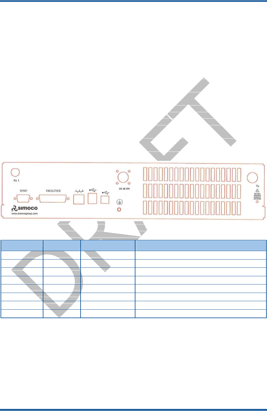
The rear panel of the SDM680 DMR base station showing all the external connections is shown below in
Figure 1. The functions of each connector on the rear panel are detailed in Table 1.
Figure 1. Layout of Rear Panel.
Table 1. Rear Panel Connections.
Connector # Conn Type Function Description
DC IN Power I/P 14.0 V DC power input
S2 RS232 Serial Port
S1 D Type Facilities
P5 RJ45 Ethernet 10/100 base-T RJ45 Ethernet connector
P4 USB Type B
Peripheral USB peripheral interface
P3 USB Type A
Host USB interface
Tx N Type Tx O/P RF Power output from the Tx
Rx 1 BNC Rx I/P Rx input for full duplex operation
Tx/Rx Connections
The Tx antenna connection on the SDB680 Base Station is provided with a 50 Ω female N-type socket,
while for the Rx antenna connection a 50 Ω female Bayonet Neill-Concelman (BNC) socket is used.
The Tx antenna cable connections must be made with 50 Ω N-type on flexible tails. The Voltage Standing
Wave Ratio (VSWR) of the Tx and Rx connections should be tested prior to use by using of a suitable test
set, e.g. an Anritsu/Wiltron S331A. A VSWR of 1.5:1 or better at the relevant Tx and Rx frequencies should
be ensured.
Mating connectors should be galvanically compatible with nickel outer and gold centre pin to minimise
passive intermodulation.

SDB680 – INSTALLATION GUIDE TNM-I-E-0046
May 15 Page 18 ELECTRICAL CONNECTIONS
A minimum of 85 dB transmit-receive isolation should be provided by the antenna system and associated
filters.
It is recommended that a good quality flexible co-axial cable is used, e.g. with double-screening braid and
multi-strand copper inner.
CAUTION
The Antenna System should be protected against lightning by means of an earthing
system and surge protection device.
Do not connect Antenna Lightning conductors to the base station or Mains Earth.
Power Connection
The DC power input is via a 2-pin IP67 DC plug connector. The two pins are wired to suit the voltage range
shown in Table 2 below.
Table 2. DC Power Connector Pin-outs.
Pin Description
1 +14.0 V
2 Ground
Figure 2. 2-pin IP67 DC Power Connector.
The equipment must be installed so that the power socket is readily accessible.
Earth Point
The earth stud on the rear panel is provided for protective earthing of the equipment. This should be
connected using heavy duty earthing wire with as few bends as possible, typically 6 mm Green/Yellow with
5 mm eyelet tag.
P3 USB A Dual
The USB Type A connector is used as the host connection. The connector pin-outs are detailed below in
Table 3.
Table 3. USB Type A Connector Pin-outs.
Pin Function
1 Vcc (+5 V)
2 Data -
3 Data +
4 Ground

SDB680 – INSTALLATION GUIDE TNM-I-E-0046
May 15 Page 19 ELECTRICAL CONNECTIONS
P4 USB B
The Universal Serial Bus (USB) Type B connector is used as the peripheral connection. The connector pin-
outs are detailed below in Table 4.
Table 4. USB Type B Connector Pin-outs.
Pin Function
1 Vcc (+5 V)
2 Data -
3 Data +
4 Ground
P5 Ethernet
The P5 Ethernet connector uses standard network cable wiring for an RJ45, which is detailed below in Table
5.
Table 5. Ethernet RJ45 Connector Pin-outs.
Pin Description
1 Tx Data+, balanced I/P 1
2 Tx Data-, balanced I/P 2
3 Rx Data+, balanced O/P 1
4 NC
5 NC
6 Rx Data-, balanced O/P 2
7 NC
8 NC
S2 Serial Port
The connector pin-outs for the 9-way D Type S2 Serial Port are shown below in Table 6.
Table 6. S2 Serial Port Connector Pin-outs.
Pin Function
1 Connected to pin 4 and 6
2 Tx 1
3 Rx 1
4 Connected to pin 1 and 6
5 0 V
6 Connected to pin 1 and 4
7 Rx 2 (opt CTS 1)
8 Tx 2 (opt RTS 1)
9 NC
1
8

SDB680 – INSTALLATION GUIDE TNM-I-E-0046
May 15 Page 20 ELECTRICAL CONNECTIONS
S1 Facilities Connector
The 25-way D Type facilities connector can be programmed for any combination of digital inputs and
outputs. The connector pin-outs for the Facilities Connector are shown below in Table 7.
Table 7. Facilities Connector Pin-outs.
Pin Function Pin Function
1 Digital Input 14 Digital Output
2 Digital Input 15 Digital Output
3 Digital Input 16 Digital Output
4 Digital Input 17 Digital Output
5 Digital Input 18 Digital Output
6 Digital Input 19 Digital Output
7 Digital Input 20 Digital Output
8 Digital Input 21 Digital Output
9 GPS Rx + 22 GPS Rx -
10 GPS Tx + 23 GPS Tx -
11 1PPS Rx + 24 1PPS Rx -
12 Digital to Analogue Converter (DAC)
Output 25 0 V
13 Supply Voltage
Maximum current provided by the supply voltage pin (pin 13) is 1 A protected by a self resetting fuse.
The Digital Outputs are open collector and able to sink 300 mA each; the total for all outputs must not
exceed 600 mA.
Digital inputs are active low. Digital high voltages should not exceed 20 V.
The GPS Rx and 1PPS Rx connections are Differential RS422.
The “Analogue Out” connection is between 0 V and 5 V and software controlled to indicate various
functions e.g. Received Signal Strength Indication (RSSI) level.
SDB680 – INSTALLATION GUIDE TNM-I-E-0046
May 15 Page 21 WALL MOUNT INSTALLATION
1
WALL MOUNT INSTALLATION
This Procedure should be followed when installing all new DMR Base Stations with a Wall Mount
cabinet.
T
OOLS
, T
EST
E
QUIPMENT AND
M
ATERIALS
R
EQUIRED
The following Tools, Test Equipment and Materials will be required to perform this procedure:
Electric Drill (preferably with Hammer Action)
7.5 mm Drill Bit
Spirit Level
Screwdriver
4 x M4 x 12 Screws (supplied)
4 x Rawlplugs (supplied)
4 x No. 12 x 1½” Woodscrews (supplied)
4 x M6 x 12 mm Pan Head Pozidriv Retaining Bolts
4 x Plastic CupWashers
Anritsu/Wiltron S331A Test Set
Earth Bonding Test Set
1.1
I
NSTALLATION OF THE
W
ALL
M
OUNT
U
NIT
1. Unpack all the equipment and retain the packaging.
2. Establish the mounting position of the base station.
CAUTION
Before drilling any walls, first check for any buried cables or pipes.
3. Ensure that there are no buried pipes or cables in the vicinity.
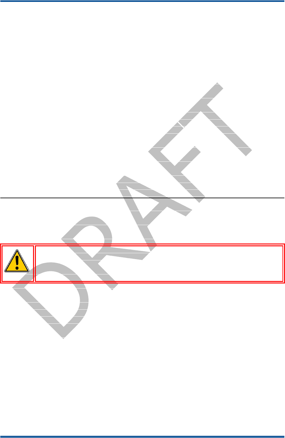
4. Referring to Figure 3 (overleaf), mark out the four holes required to secure the wall mount to the wall.
5. Using the drill and 7.5 mm drill bit, drill the four holes to a depth of 50 mm.
6. Place the four masonry rawlplugs into the four holes and ensure they are fully inserted. If necessary,
use a small hammer to drive them fully home.
7. Attach the two wall mount brackets to the wall mount case using M6 nuts and washers (see Figure 4
overleaf).
8. Using the M5 nuts and washers, fit the wall mount inner chassis plate into the wall mount unit (see
Figure 4 overleaf).
9. Using a screwdriver and the four No. 12 x 1.5” woodscrews, secure the wall mount unit to the wall
surface.
SDB680 – INSTALLATION GUIDE TNM-I-E-0046
May 15 Page 22 WALL MOUNT INSTALLATION
Figure 3. Mounting holes drilling template (dimensions in mm).
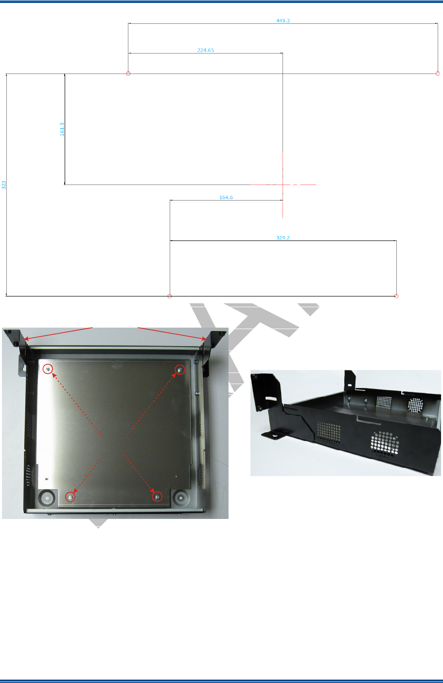
Figure 4. Wall Mount Assembly.
1.2
F
ITTING THE
SDB680
BASE
S
TATION
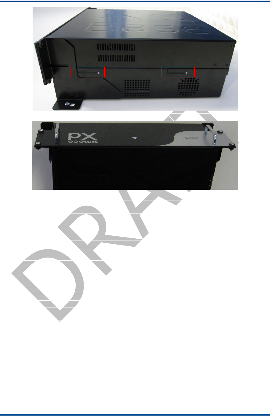
10. Ensuring that all cables are clear of the mounting position and cannot be trapped, offer the base station
up to the wall mount unit and fit the four keyhole standoffs on the base station (two per side) into the
mounting grooves on the wall mount case (see Figure 5 overleaf for details).
11. Secure the front panel of the base station to the wall mount brackets using four M6 x 12 mm pozidriv
retaining bolts with plastic cup washers (two per side) (see Figure 6 overleaf).
Inner Chassis Plate
securing points
Wall Mount Brackets
SDB680 – INSTALLATION GUIDE TNM-I-E-0046
May 15 Page 23 WALL MOUNT INSTALLATION
Figure 5. Keyhole Standoff mounting locations.
Figure 6. Base Station secured to Wall Mount.
1.3
E
LECTRICAL
C
ONNECTIONS
12. Refer to the Electrical Connections section, for full details of all connections and the connector pin-
outs.
13. Using a suitable test set, e.g. an Anritsu/Wiltron S331A, check the Tx and Rx antenna connections for
a VSWR of 1.5:1 or better at the relevant Tx and Rx Frequencies.
14. On the SDB680 Base Station rear panel, carry out the following:
14.1. Connect the Tx and Rx antenna cables to their respective connectors.
14.2. Ensuring that the power source is switched off, connect the DC power cable from the ‘DC IN’
connector to the power source.
15. Carry out the configuration of the SDB680 in accordance with Section 3 – Configuration of New
Tier II Base Station or Section 4 – Configuration of New Tier III Base Station as appropriate.

SDB680 – INSTALLATION GUIDE TNM-I-E-0046
May 15 Page 24 RACK MOUNT INSTALLATION
2
RACK MOUNT INSTALLATION PROCEDURE
The SDB680 Base Station is designed to be fitted in a standard 403 mm (19”) rack. This procedure
should be followed when installing all new SDB680s into a 19” racking system.
T
OOLS
, T
EST
E
QUIPMENT AND
M
ATERIALS
R
EQUIRED
The following Tools, Test Equipment and Materials will be required to perform this procedure:
Pozidriv Screwdriver
4 x M6 x 12 mm Pozidriv Retaining Bolts
4 x M6 x 16 mm Pozidriv Retaining Bolts
8 x M6 Nuts and Plain Washers
M6 Cage Nuts
Anritsu/Wiltron S331A Test Set
Earth Bonding Test Set
2.1
R
ACK
P
REPARATION
Note.
Rack runner fittings differ between the various rack manufacturers. If the procedure described
below does not apply to the type of rack being used, the procedure should be modified to suit.
1. Ensure that the rack chosen for installation is firmly bolted together and is securely anchored to the
floor or wall to prevent overbalancing.
2. In the rack, plan out the locations of equipment before commencing installation.
Notes:
(i).
Each SDB680 requires 2U height of rack space.
(ii).
Unused space should be blanked off to prevent uncontrolled circulation of air.
(iii).
If used, the associated PSU TRAY requires either 1U or 2U height of rack space and is designed to
locate adjacent to the base station.
(iv).
When the SDB680 is installed into a rack, support shelves or side slide runners should be used.
These are available from Simoco and supplied as a pair with all the necessary screws for securing
them.
CAUTION
EQUIPMENT DAMAGE. When the SDB680 Base Station is installed into a rack, DO
NOT use the front panel attachment points to support the full weight of the equipment
or damage to the equipment may result. Suitable shelves or supports MUST be
provided to support the body of the base station along the length of each side.
3. Unpack all the equipment and retain the packaging.
SDB680 – INSTALLATION GUIDE TNM-I-E-0046
May 15 Page 25 RACK MOUNT INSTALLATION
2.2
F
ITTING
T
HE
SDB680 B
ASE
S
TATION
4. To fit the SDB680 into a rack on a support shelf, carry out the following:
4.1. Hook the support shelves onto either side (internal) of the rack at equal heights.
4.2. Fit the M6 cage nuts into the appropriate positions on the front rack mounting support rails.
4.3. At the front of the rack, position the rear of the base station onto the support shelves and slide
the base station into the rack, checking that it does not catch on anything.
4.4. Secure the base station into the rack using the four M6 x 12 mm pozidriv retaining bolts with
plastic cup washers (two per side).
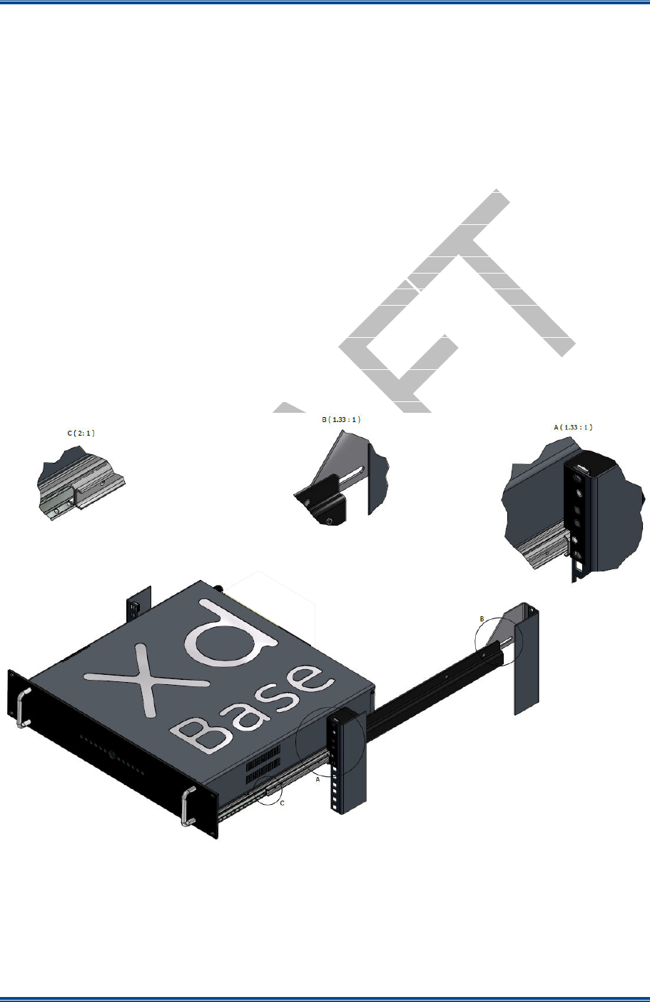
5. To fit the SDB680 into a rack using rack mount supports, carry out the following (see Figure 7
below):
5.1. Fit the slide rails to the pair of front rack mount support brackets using the four screws provided
(two per slide rail).
5.2. Ensuring that the left-hand and right-hand rack mount support brackets are paired up correctly,
fit the front and rear rack mount support brackets together using four M6 nuts and plain washers
(two each per side) do not fully tighten at this stage.
Figure 7. Inserting and securing the base station into the rack.
5.3. Fit the pair of rack mount support assemblies into the rack at suitable heights as follows:
5.3.1. Secure the rack mount support assemblies to the front rack mounting support rails
using four M6 nuts and plain washers (two each per side) provided.
SDB680 – INSTALLATION GUIDE TNM-I-E-0046
May 15 Page 26 RACK MOUNT INSTALLATION
5.3.2. Adjust the rack mount support assemblies to the correct length and secure them to the
rear rack mounting support rails using the four M6 x 16 mm pan head pozidriv
retaining bolts and cage nuts (two each per side).
5.3.3. Tighten the four M6 nuts that secure the front and rear rack mount support brackets
together.
5.4. Fit M6 cage nuts into the appropriate positions on the front rack mounting support rails so that
the base station can be secured into the rack.
5.5. Pull out the slide runners and fit the base station onto the runners. Ensure that the keyhole
standoffs on the base station (two per side) are correctly located in the keyhole slots on the slide
rails.
6. Secure the base station into the rack using the four M6 x 12 mm pozidriv retaining screws (with plastic
cup washers).
CAUTION
EQUIPMENT DAMAGE. During installation operations, the Torque settings must be
adhered to or damage to the equipment may result.
7. Tighten all four of the M6 screws to a torque of 2 Nm to secure the base into the rack.
2.3
E
LECTRICAL
C
ONNECTIONS
8. Refer to the Electrical Connections section, for full details of all connections and the connector pin-
outs.
9. Using a suitable test set, e.g. an Anritsu/Wiltron S331A, check the Tx and Rx antenna connections for
a VSWR of 1.5:1 or better at the relevant Tx and Rx Frequencies.
10. On the SDB680 rear panel, carry out the following:
10.1. Connect the Tx and Rx antenna cables to their respective N-type connectors.
10.2. Ensuring that the power source is switched off, connect the DC power cable from the ‘DC IN’
connector to the power source.
11. Carry out the configuration of the SDB680 in accordance with Section 3 – Configuration of New
Tier II Base Station or Section 4 – Configuration of New Tier III Base Station as appropriate.
SDB680 – INSTALLATION GUIDE TNM-I-E-0046
May 15 Page 27 CONFIGURATION TIER II BASE
3
CONFIGURATION OF NEW TIER II BASE STATION
This Procedure should be followed when configuring all new Tier II SDB680 Base Stations after their
initial installation in a new system.
T
OOLS
, T
EST
E
QUIPMENT AND
M
ATERIALS
R
EQUIRED
The following Tools, Test Equipment and Materials will be required to perform this procedure:
Dummy Load
Personal Computer
Software Applications:
Simoco Digital Management Terminal (SDMT)
Simoco IP Configuration Tool
Notes
(i).
The software applications listed above are available for download on the Simoco website
http://www.simocogroup.com via the Partner Portal. To access the Partner Portal a Username and
Password will be required.
(ii).
To request access to the partner portal please contact your local business development manager or
alternatively contact the relevant Simoco Customer Services (see Support Page for details).
3.1
SDB680 P
REPARATION
WARNING
RF RADIATION. A RF RADIATION HAZARD EXISTS IN THIS
EQUIPMENT. TO AVOID RF INJURY, DO NOT TOUCH THE ANTENNA
WHEN THE TRANSMITTER IS IN USE. DO NOT OPERATE
TRANSMITTER WITH ANTENNA DISCONNECTED. REFER TO EU
DIRECTIVE 2004/40/EC DATED 29 APRIL 2004.
1. Ensure that the SDB680 base stations are securely fitted into the rack and that the power and antenna
cables are connected on the rear panel.
2. On the SDB680 rear panel, connect the Tx antenna socket to a suitable dummy load (for the 50 W
base a minimum 60 Watt load can be used provided that it is suitable for use).
3. Connect an Ethernet switch cable to the Ethernet socket.
4. Switch on the power for the system and, in turn, power up each SDB680 base station.
3.2
SDMT I
NSTALLATION AND
P
REPARATION
5. Refer to the SDMT DMR Tier II User Manual [2] and carry out the following:
5.1. Install the SDMT software in accordance with Section 1.2 – Software Installation.
5.2. Prepare the SDMT software for use in accordance with Section 2.2 – SDMT Preparation.
5.3. Create or establish a connection to a suitable Microsoft SQL Server database in accordance with
Section 2.3 – Database Connection.

SDB680 – INSTALLATION GUIDE TNM-I-E-0046
May 15 Page 28 CONFIGURATION TIER II BASE
3.3
I
NSTALLING THE
S
IMOCO
IP C
ONFIGURATION
S
ERVER
6. Refer to the Simoco IP Configuration Tool User Manual [3] and install the Simoco IP Configuration
Server software in accordance with Section 1.3 – Software Installation.
7. After installing the Simoco IP Configuration Tool software, ensure that the PC on which the software
is installed is connected to the Ethernet switch via a CAT 5 Ethernet cable.
3.4
IP A
DDRESS
C
ONFIGURATION
8. On the PC, start the Simoco IP Configuration Tool.
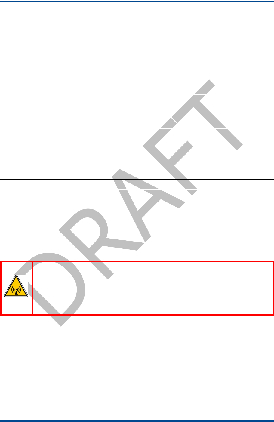
9. If the PC has more than one IP address or Network Connection, when the IP Configuration Tool is
started, the Interface Selection screen will be displayed (see Figure 8 below).
Figure 8. Interface Selection screen.
10. On the Interface Selection screen, select the relevant IP address that is to be used for communicating
with the base station(s).
11. Once the IP address has been selected the Simoco IP Configuration Tool main screen will be displayed
(see Figure 9 below).
Figure 9. IP Configuration Tool main screen
12. Refer to the Simoco IP Configuration Tool User Manual [3] and configure the IP Address for the
relevant MAC Address listed in the data grid of the main screen in accordance with Section 2.2 –
Configuring an IP Address.
3.5
C
ONFIGURING THE
DMR B
ASE
13. On the SDMT main screen, carry out the following:
13.1. On the ribbon bar, select the ‘DMR Tier II’ tab.

SDB680 – INSTALLATION GUIDE TNM-I-E-0046
May 15 Page 29 CONFIGURATION TIER II BASE
13.2. On the Site View tab of the Navigation Pane, from the navigation tree, click on the ‘System’
branch to expand it. Click on the ‘Site 1’ node displayed.
13.3. On the Ribbon bar, select the ‘Add Digital Base’ button to add a digital base to Site 1 on the
navigation tree.
13.4. On the Site View tab of the Navigation Pane, from the navigation tree, select the new DMR
Base that has just been added to the navigation tree. The Base configuration page will be
displayed in the configuration page area (see Figure 10 below).
Figure 10. Base configuration page – Base Settings tab.
13.5. On the base Configuration page on the Base Settings tab, set the ‘IP Address’ to that sent to the
base with the IP Configuration tool.
13.6. On the tab of the base configuration page, select the icon that is displayed to save the changes
that have been made to the configuration page.
13.7. Create a working configuration that includes the new DMR Base in accordance with the SDMT
User Manual [2] and appropriate for the system in which it is installed.
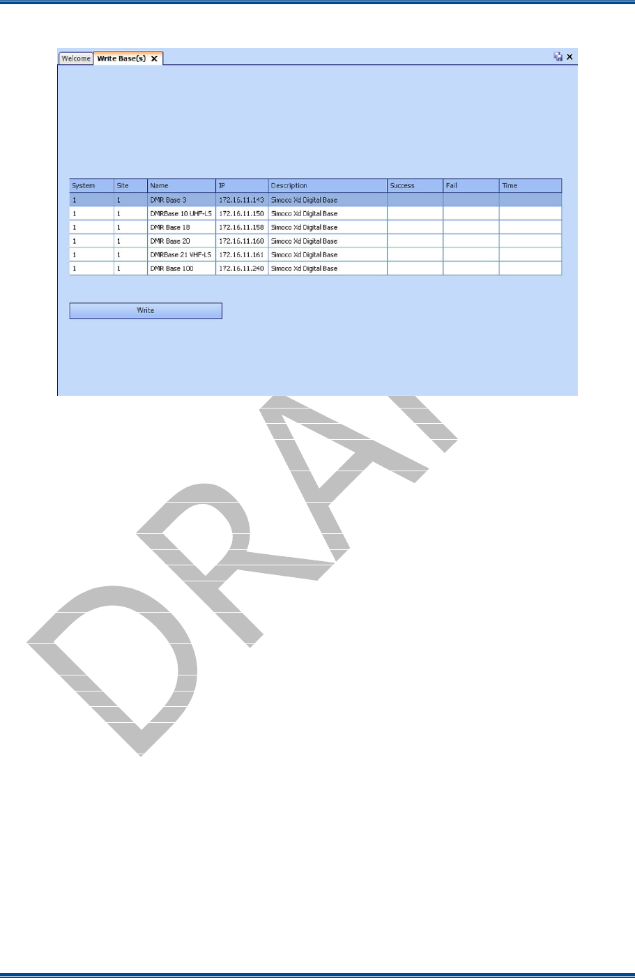
13.8. On the DMR Tier II ribbon bar, select the ‘Write’ button. The ‘Write Base(s)’ page will be
displayed (see Figure 11 overleaf) and any open base configuration pages will be closed.
13.9. On the ‘Write Base(s)’ page, carry out the following:
13.9.1. Select the new DMR Base that is included in the working configuration.
13.9.2. Select the ‘Write’ button. A progress bar will briefly be displayed.
13.9.3. After a few seconds, check that a green dot appears in the Success column for the
selected base (indicating that the Write operation has been successful) and a ‘Reboot’
button appears at the bottom of the page.
Note.
To complete the software configuration update procedure for the selected DMR Base, the base must
be re-booted.
SDB680 – INSTALLATION GUIDE TNM-I-E-0046
May 15 Page 30 CONFIGURATION TIER II BASE
13.9.4. Select the Reboot button to enable the base to use the new configuration.
Figure 11. Write Base(s) page.
SDB680 – INSTALLATION GUIDE TNM-I-E-0046
May 15 Page 31 CONFIGURATION TIER III BASE
4
CONFIGURATION OF NEW TIER III BASE STATION
This Procedure should be followed when configuring all new Tier III SDB680 Base Stations after their
initial installation in a new system.
T
OOLS
, T
EST
E
QUIPMENT AND
M
ATERIALS
R
EQUIRED
The following Tools, Test Equipment and Materials will be required to perform this procedure:
Dummy Load
Personal Computer
Software Applications:
SDMT
Simoco IP Configuration Tool
Notes
(i).
The software applications listed above are available for download on the Simoco website
http://www.simocogroup.com via the Partner Portal. To access the Partner Portal a Username and
Password will be required.
(ii).
To request access to the partner portal please contact your local business development manager or
alternatively contact the relevant Simoco Customer Services (see Support Page for details).
4.1
S
OFTWARE
L
ICENCES
All Tier III Base Stations require a Software Licence in order to operate; these licences can be obtained from
Simoco. If a Tier III Base Station is added to an existing Tier III system, the software licences for all the
base stations on that system will have to be updated.
It is assumed that all the relevant software licences required have been obtained before commencing this
procedure and that they have been uploaded onto a suitable PC.
4.2
SDB680 P
REPARATION
WARNING
RF RADIATION. A RF RADIATION HAZARD EXISTS IN THIS
EQUIPMENT. TO AVOID RF INJURY, DO NOT TOUCH THE ANTENNA
WHEN THE TRANSMITTER IS IN USE. DO NOT OPERATE
TRANSMITTER WITH ANTENNA DISCONNECTED. REFER TO EU
DIRECTIVE 2004/40/EC DATED 29 APRIL 2004.
1. Ensure that the SDB680 base stations are securely fitted into the rack and that the power and antenna
cables are connected on the rear panel.
2. On the SDB680 rear panel, connect the Tx antenna socket to a suitable dummy load (for the 50 W
base a minimum 60 Watt load can be used provided that it is suitable for use).
3. Connect an Ethernet switch cable to the Ethernet socket.
4. Switch on the power for the system and, in turn, power up each SDB680 base station.
4.3
SDMT I
NSTALLATION AND
P
REPARATION
5. Refer to the SDMT User Manual [2] and carry out the following:
SDB680 – INSTALLATION GUIDE TNM-I-E-0046
May 15 Page 32 CONFIGURATION TIER III BASE
5.1. Install the SDMT software in accordance with Section 1.2 – Software Installation.
5.2. Prepare the SDMT software for use in accordance with Section 2.2 – SDMT Preparation.
5.3. Create or establish a connection to a suitable Microsoft SQL Server database in accordance
with Section 2.2.3 – Database Connection.
4.4
I
NSTALLING THE
S
IMOCO
IP C
ONFIGURATION
S
ERVER
6. Refer to the Simoco IP Configuration Tool User Manual [3] and install the Simoco IP Configuration
Server software in accordance with Section 1.3 – Software Installation.
7. After installing the Simoco IP Configuration Tool software, ensure that the PC on which the software
is installed is connected to the Ethernet switch via a CAT 5 Ethernet cable.
4.5
IP A
DDRESS
C
ONFIGURATION
8. On the PC, start the Simoco IP Configuration Tool.
9. If the PC has more than one IP address or Network Connection, when the IP Configuration Tool is
started, the Interface Selection screen will be displayed (see Figure 12 below).
Figure 12. Interface Selection screen.
10. On the Interface Selection screen, select the relevant IP address that is to be used for communicating
with the base station(s).
11. Once the IP address has been selected the Simoco IP Configuration Tool main screen will be displayed
(see Figure 13 below).
Figure 13. IP Configuration Tool main screen

SDB680 – INSTALLATION GUIDE TNM-I-E-0046
May 15 Page 33 CONFIGURATION TIER III BASE
12. Refer to the Simoco IP Configuration Tool User Manual [3] and configure the IP Address for the
relevant MAC Address listed in the data grid of the main screen in accordance with Section 2.2 –
Configuring an IP Address.
4.6
C
ONFIGURING THE
DMR B
ASE
4.6.1
Platform and Application Software Update
13. On the PC, open an internet browser and access the Simoco webpage.
14. On the Simoco webpage, select ‘Partner Login’ and login to the Partner Portal area.
15. When logged in to the Partner Portal, navigate to the ‘Resource Library’ > ‘Software Downloads’ >
‘DMR’ > ‘Simoco Xd Infrastructure’ page and ensure that you have the latest version of the ‘DMR
Tier III’ > ‘DMR Base’ software. If necessary, download the latest software to the PC.
Note.
The versions of DMR Base software listed and available on the Partner Portal contain two software
files. These are the Cerebral Platform software and the Application software. The files are in the
form CerebralPlatform_R.X.X.X.tar.gz and DMRT3_RX.X.X.tar.gz, where RX.X.X refers to the
version of software released in each case.
16. On the PC, start and login to the SDMT. The System Selector screen will be displayed.
17. On the ‘System Selector’ screen, carry out either of the following:
17.1. If the base station is to be added to an existing Tier III system, select the system number from
the displayed list and select the ‘OK’ button.
17.2. If the base station is to be added to a new Tier III system, enter the system number for the new
system and select the ‘OK’ button.
Note.
The Tier III system number selected or entered above must match that entered when configuring
the IP address for the Tier III base station. Refer to Para 12 above and Para 2.3 of Section 2.2 –
Configuring an IP Address in the Simoco IP Configuration Tool User Manual [3] for clarification.
18. On the SDMT main screen, carry out the following:
18.1. On the ribbon bar, select the DMR Tier III tab.
18.2. On the DMR Tier III ribbon bar, select the System Commands button. The System I/O page
will be displayed.
18.3. On the System I/O page, select the ‘Browse’ button for relevant software you wish to upload
(i.e. Cerebral Platform or Application Software). An open file dialogue window will be
displayed.
19. On the ‘Open’ file window, navigate to and select the latest version of DMR Tier III software (i.e.
Cerebral Platform or Application Software) downloaded at Para 15. Select the Open button to load
the file into the SDMT.
20. Repeat Para 18.3 and Para 19 for the other type of software (i.e. Cerebral Platform or Application
Software) as required.
21. On the SDMT, on the System I/O Page, carry out the following:

SDB680 – INSTALLATION GUIDE TNM-I-E-0046
May 15 Page 34 CONFIGURATION TIER III BASE
21.1. In the System Monitor area, on the navigation tree, right click on the Base that you wish to
upload the software to. Menu options will be displayed.
21.2. From the menu options, select ‘Update’ > ‘Update Software’.
21.3. In the Comms History area, confirm that a ‘Starting Update Software’ message is displayed.
21.4. The progress of the software update operation will be displayed in the ‘Current Message
Progress’ area.
21.5. In the Comms History area, after a short delay, confirm that a ‘Completed Update Software’
message is displayed.
4.6.2
Software Licence Update
22. On the SDMT, on the System I/O Page, select the ‘Browse’ button for the Licence file. An Open file
dialogue window will be displayed.
23. On the ‘Open’ file window, navigate to and select the relevant software licence file. Select the Open
button to load the file into the SDMT.
24. On the SDMT main screen, on the System I/O page, carry out the following:
24.1. In the System Monitor area, on the navigation tree, right click on the VAC for the system.
Menu options will be displayed.
24.2. From the VAC menu options, select ‘Update’ > ‘Update Software’.
24.3. In the Comms History area, confirm that a ‘Starting Update Software’ message is displayed.
24.4. The progress of the update operation will be displayed in the ‘Current Message Progress’ area.
24.5. In the Comms History area, after a short delay, confirm that a ‘Completed Update Software’
message is displayed.
4.6.3
Configuration Creation and Upload
25. Refer to Part 3 of the SDMT User Manual [2] and create a working configuration that includes the
new DMR Base and appropriate for the system in which it is installed.
26. When creating a working configuration, ensure that any changes to the configuration are saved by
selecting the icon that will be displayed on the page tab of the relevant configuration pages. This
will save the changes to the local SQL Server ® database stored on the PC.
27. On the SDMT main screen, on the ribbon bar, select the System Commands button. The System I/O
configuration page will be displayed.
28. On the System I/O page, carry out the following:
28.1. In the ‘Select Read/Write System Areas’ box, depending on the configuration you wish to
write, select either the ‘Configuration’, the ‘Subscribers’ or both. Select the ‘Write to System’
button.
28.2. In the Comms History area, confirm that a ‘Starting Write All Config’ message is displayed.
28.3. The progress of the write operation will be displayed in the ‘Current Message Progress’ area.
28.4. In the Comms History area, after a short delay, confirm that a ‘Completed Write All Config’
message is displayed.

SDB680 – INSTALLATION GUIDE TNM-I-E-0046
May 15 Page 35 CONFIGURATION TIER III BASE
28.5. When the write operation is completed, the success or failure of the operation for each VAC,
Site or Base will be indicated in the Comms History area.
4.6.4
Enable Bases
29. On the system I/O page, in the System Monitor area, on the navigation tree, carry out the following:
29.1. To enable all the bases on a system, carry out the following:
29.1.1. Right click on the VAC that you wish to enable. Menu options will be displayed.
29.1.2. From the menu options, select ‘Site Options’ > ‘Enable Site(s)’. The sites enable
warning message will be displayed.
29.2. To enable an individual base, carry out the following:
29.2.1. Right click on the Base that you wish to enable. Menu options will be displayed.
29.2.2. From the menu options, select ‘Base Operations’ > ‘Enable Base(s)’. The base enable
warning message will be displayed.
29.3. On the relevant warning message, select ‘Yes’ to continue.
29.4. In the System Monitor area, on the navigation tree, confirm that the status notification that was
alongside the relevant VAC, Site or individual base has now disappeared.
29.5. In the Comms History area, after a short delay, confirm that the relevant ‘Completed Enabling
Base’ message(s) is displayed.

SDB680 – INSTALLATION GUIDE TNM-I-E-0046
May 15 Page 36 CONFIGURATION TIER II – TIER III
5
BASE CONFIGURATION TIER II TO TIER III
This Procedure should be followed when configuring a Tier II SDB680 Base Station into a Tier III
SDB680 Base Station.
T
OOLS
, T
EST
E
QUIPMENT AND
M
ATERIALS
R
EQUIRED
The following Tools, Test Equipment and Materials will be required to perform this procedure:
PC with the following Software Applications installed:
SDMT
Simoco IP Configuration Tool
Notes
(i).
The software applications listed above are available for download on the Simoco website
http://www.simocogroup.com via the Partner Portal. To access the Partner Portal a Username and
Password will be required.
(ii).
To request access to the partner portal please contact your local business development manager or
alternatively contact the relevant Simoco Customer Services (see Support Page for details).
5.1
T
IER
III B
ASE
P
REREQUISITES
Before commencing this procedure to configure a Tier II Base Station into a Tier III Base Station, it is
assumed that the base station has already been fitted into a rack and is connected to the network as a Tier II
Base.
It as also assumed that the SDMT and Simoco IP Configuration Tool software applications have been
installed on a PC and have previously been used.
5.2
S
OFTWARE
L
ICENCES
All Tier III Base Stations require a Software Licence in order to operate; these licences can be obtained from
Simoco. If a Tier III Base Station is added to an existing Tier III system, the software licences for all the
base stations on that system will have to be updated.
It is assumed that all the relevant software licences required have been obtained before commencing this
procedure and that they have been uploaded onto a suitable PC.
5.3
IP A
DDRESS
C
ONFIGURATION
1. If the relevant base station has already been allocated an IP address, note the IP address.
2. Ensure that the PC is connected to the Ethernet switch via a CAT 5 Ethernet cable and the PC has a
fixed IP address in the same subnet as the bases.
3. On the PC, start the Simoco IP Configuration Tool.
4. If the PC has more than one IP address or Network Connection, when the IP Configuration Tool is
started, the Interface Selection screen will be displayed.
5. On the Interface Selection screen, select the relevant IP address that is to be used for communicating
with the base station(s).
6. Once the IP address has been selected the Simoco IP Configuration Tool main screen will be
displayed.

SDB680 – INSTALLATION GUIDE TNM-I-E-0046
May 15 Page 37 CONFIGURATION TIER II – TIER III
7. Refer to the Simoco IP Configuration Tool User Manual [3] and configure a Tier II IP Address for the
relevant MAC Address listed in the data grid of the main screen in accordance with Section 2.2 –
Configuring an IP Address.
5.4
C
ONFIGURING THE
DMR B
ASE
5.4.1
Platform and Application Software Update
8. On the PC, open an internet browser and access the Simoco webpage.
9. On the Simoco webpage, select ‘Partner Login’ and login to the Partner Portal area.
10. When logged in to the Partner Portal, navigate to the ‘Resource Library’ > ‘Software Downloads’ >
‘DMR’ > ‘Simoco Xd Infrastructure’ page and ensure that you have the latest version of the ‘DMR
Tier III’ > ‘DMR Base’ software. If necessary, download the latest software to the PC.
Note.
The versions of DMR Base software listed and available on the Partner Portal contain two software
files. These are the Cerebral Platform software and the Application software. The files are in the
form CerebralPlatform_R.X.X.X.tar.gz and DMRT3_RX.X.X.tar.gz, where RX.X.X refers to the
version of software released in each case.
11. On the PC, start and login to the SDMT. The System Selector screen will be displayed.
12. On the ‘System Selector’ screen, carry out either of the following:
12.1. If the base station is to be added to an existing Tier III system, select the system number from
the displayed and select the ‘OK’ button.
12.2. If the base station is to be added to a new Tier III system, enter the system number for the new
system and select the ‘OK’ button.
13. On the SDMT main screen, carry out the following:
13.1. On the ribbon bar, select the DMR Tier II tab.
13.2. On the Site View tab of the Navigation Pane, from the navigation tree, click on the ‘System’
branch to expand it. Click on the ‘Site 1’ node displayed.
13.3. On the DMR Tier II ribbon bar, select the ‘Add Digital Base’ button to add a digital base to
Site 1 on the navigation tree.
13.4. On the Site View tab of the Navigation Pane, from the navigation tree, select the new DMR
Base that has just been added to the navigation tree. The Base configuration page will be
displayed in the configuration page area.
13.5. On the base Configuration page on the Base Settings tab, set the ‘IP Address’ to that of the
new Tier III base station noted in Para 1 or that sent to the base with the IP Configuration tool
as appropriate.
13.6. On the tab of the base configuration page, select the icon that is displayed to save the
changes that have been made to the configuration page.
13.7. On the DMR Tier II ribbon bar, select the ‘Software Upload’ button. The ‘Upload to Base(s)’
page will be displayed.
13.7.1. On the Upload to Base(s) page, select the ‘Browse’ button for the Application
Software File. An Open file dialogue window will be displayed.

SDB680 – INSTALLATION GUIDE TNM-I-E-0046
May 15 Page 38 CONFIGURATION TIER II – TIER III
14. On the ‘Open’ file window, navigate to and select the latest version of the DMR Tier III Application
Software downloaded at Para 10. Select the Open button to load the file into the SDMT.
15. On the SDMT main screen, on the Upload to Base(s) page, select the ‘Browse’ button for the Cerebral
Platform File. An Open file dialogue window will be displayed.
16. On the ‘Open’ file window, navigate to and select the latest version of the DMR Tier III Cerebral
Platform software downloaded at Para 10. Select the Open button to load the file into the SDMT.
17. On the SDMT main screen, carry out the following:
17.1. On the Upload to Base(s) page, carry out the following:
17.1.1. Select the base(s) you wish to upload the software to.
17.1.2. Select the ‘Upload’ button to programme the base with the Application Software and
the Cerebral Platform.
17.2. On the DMR Tier II ribbon bar, select the Re-boot button. The Re-boot Base(s) page will be
displayed.
17.3. On the Re-boot Base(s) page, select the base station(s) that the software was uploaded to and
select the ‘Re-boot’ button. The base station(s) will re-boot and load the new versions of
software.
5.4.2
Tier III IP Address Configuration
18. On the IP Configuration Tool, in the data grid of the main screen, select the relevant MAC Address for
the Tier II Base.
19. Refer to the Simoco IP Configuration Tool User Manual [3] and configure a Tier III IP Address for
the relevant MAC Address listed in the data grid of the main screen in accordance with Section 2.2 –
Configuring an IP Address. Ensure that the ‘System’, ‘VAC’, ‘Site’ and ‘Base’ details entered are
relevant to the Tier III system.
Note.
When configuring the IP address for the Tier III base station, the Tier III ‘System’ number entered
above must match the system number that the Tier III base station is to be added to. Refer to Para
12 above and Para 2.3 of Section 2.2 – Configuring an IP Address in the Simoco IP Configuration
Tool User Manual [3] for clarification.
5.4.3
Software Licence Update
20. On the SDMT main screen, on the ribbon bar, select the DMR Tier III tab.
20.1. On the DMR Tier III ribbon bar, select the System Commands button. The System I/O
configuration page will be displayed.
20.2. On the System I/O page, in the System Monitor area, expand the navigation tree and check
that the new Tier III base has been added to the system.
20.3. On the System I/O page, select the ‘Browse’ button for the Licence file. An Open file
dialogue window will be displayed.
21. On the ‘Open’ file window, navigate to and select the relevant software licence file. Select the Open
button to load the file into the SDMT.
22. On the SDMT main screen, on the System I/O page, carry out the following:

SDB680 – INSTALLATION GUIDE TNM-I-E-0046
May 15 Page 39 CONFIGURATION TIER II – TIER III
22.1. In the System Monitor area, on the navigation tree, right click on the VAC for the system.
Menu options will be displayed.
22.2. From the VAC menu options, select ‘Update’ > ‘Update Software’.
22.3. In the Comms History area, confirm that a ‘Starting Update Software’ message is displayed.
22.4. The progress of the update operation will be displayed in the ‘Current Message Progress’ area.
22.5. In the Comms History area, after a short delay, confirm that a ‘Completed Update Software’
message is displayed.
22.6. In the System Monitor area, on the navigation tree, right click on the VAC for the system.
Menu options will be displayed.
22.7. From the VAC menu options, select ‘Base Operations’ > ‘Reboot Base(s)’. The Reboot
Base(s) warning message will be displayed.
22.8. On the Reboot Base(s) warning message, select ‘Yes’ to continue.
22.9. In the Comms History area, after a short delay, confirm that a ‘Resetting VAC’ message is
displayed.
22.10. In the Comms History area, various messages for the reboot operation will be displayed.
Eventually, as the reboot of each base station in the Tier III system is completed, an
appropriate ‘Discovered Base’ message will be displayed.
5.4.4
Configuration Creation and Upload
23. On the SDMT main screen, carry out the following:
23.1. Refer to Part 3 of the SDMT User Manual [2] and create a working configuration that includes
the new DMR Base and appropriate for the system in which it is installed.
23.2. When creating a working configuration, ensure that any changes to the configuration are saved
by selecting the icon that will be displayed on the page tab of the relevant configuration
pages. This will save the changes to the local SQL Server ® database stored on the PC.
23.3. On the ribbon bar, select the System Commands button. The System I/O configuration page
will be displayed.
23.4. On the System I/O page, carry out the following:
23.4.1. In the ‘Select Read/Write System Areas’ box, depending on the configuration you
wish to write, select either the ‘Configuration’, the ‘Subscribers’ or both. Select the
‘Write to System’ button.
23.4.2. In the Comms History area, confirm that a ‘Starting Write All Config’ message is
displayed.
23.4.3. The progress of the write operation will be displayed in the ‘Current Message
Progress’ area.
23.4.4. In the Comms History area, after a short delay, confirm that a ‘Completed Write All
Config’ message is displayed.
23.4.5. When the write operation is completed, the success or failure of the operation for each
VAC, Site or Base will be indicated in the Comms History area.

SDB680 – INSTALLATION GUIDE TNM-I-E-0046
May 15 Page 40 CONFIGURATION TIER II – TIER III
5.4.5
Enable New Tier III Base
24. On system I/O page, in the System Monitor area, carry out the following:
24.1. On the navigation tree, right click on the new Tier III Base that you wish to enable. Menu
options will be displayed.
24.2. From the menu options, select ‘Base Operations’ > ‘Enable Base(s)’. The base enable
warning message will be displayed.
25. On the base enable warning message, select ‘Yes’ to continue.
26. On system I/O page, carry out the following:
26.1. In the System Monitor area, on the navigation tree, confirm that the status notification that was
alongside the relevant base has now disappeared.
26.2. In the Comms History area, after a short delay, confirm that the ‘Completed Enabling Base’
message is displayed.

SDB680 – INSTALLATION GUIDE TNM-I-E-0046
May 15 Page 41 CONFIGURATION TIER III – TIER II
6
BASE CONFIGURATION TIER III TO TIER II
This Procedure should be followed when configuring a Tier III Base Station into a Tier II SDB680
Base Station.
T
OOLS
, T
EST
E
QUIPMENT AND
M
ATERIALS
R
EQUIRED
The following Tools, Test Equipment and Materials will be required to perform this procedure:
PC with the following Software Applications installed:
SDMT
Simoco IP Configuration Tool
Notes
(i).
The software applications listed above are available for download on the Simoco website
http://www.simocogroup.com via the Partner Portal. To access the Partner Portal a Username and
Password will be required.
(ii).
To request access to the partner portal please contact your local business development manager or
alternatively contact the relevant Simoco Customer Services (see Support Page for details).
6.1
T
IER
II B
ASE
P
REREQUISITES
Before commencing this procedure to configure a Tier III Base Station into a Tier II Base Station, it is
assumed that the base station has already been fitted into a rack and is connected to the relevant system.
It as also assumed that the SDMT and Simoco IP Configuration Tool software applications have been
installed on a PC and have previously been used.
6.2
IP A
DDRESS
C
ONFIGURATION
1. If the relevant base station has already been allocated an IP address, note the IP address.
2. If the relevant base station has not been allocated an IP address, carry out the IP address configuration
as described below.
3. Ensure that the PC is connected to the Ethernet switch via a CAT 5 Ethernet cable and the PC has a
fixed IP address in the same subnet as the bases.
4. On the PC, start the Simoco IP Configuration Tool.
5. If the PC has more than one IP address or Network Connection, when the IP Configuration Tool is
started, the Interface Selection screen will be displayed.
6. On the Interface Selection screen, select the relevant IP address that is to be used for communicating
with the base station(s).
7. Once the IP address has been selected the Simoco IP Configuration Tool main screen will be
displayed.
8. Refer to the Simoco IP Configuration Tool User Manual [3] and configure the IP Address for the
relevant MAC Address listed in the data grid of the main screen in accordance with Section 2.2 –
Configuring an IP Address.

SDB680 – INSTALLATION GUIDE TNM-I-E-0046
May 15 Page 42 CONFIGURATION TIER III – TIER II
6.3
C
ONFIGURING THE
DMR B
ASE
6.3.1
Changing the Platform and Application Software
9. On the PC, open an internet browser and access the Simoco webpage.
10. On the Simoco webpage, select ‘Partner Login’ and login to the Partner Portal area.
11. When logged in to the Partner Portal, navigate to the ‘Resource Library’ > ‘Software Downloads’ >
‘DMR’ > ‘Simoco Xd Infrastructure’ page and ensure that you have the latest version of the ‘DMR
Tier II’ > ‘DMR Base’ software. If necessary, download the latest software to the PC.
Note.
The versions of DMR Base software listed and available on the Partner Portal contain two software
files. These are the Cerebral Platform software and the Application software. The files are in the
form CerebralPlatform_R.X.X.X.tar.gz and DMRT2_RX.X.X.tar.gz, where RX.X.X refers to the
version of software released in each case.
12. On the PC, start and login to the SDMT.
13. On the SDMT main screen, carry out the following:
13.1. On the ribbon bar, select the ‘DMR Tier II’ tab.
13.2. On the Site View tab of the Navigation Pane, from the navigation tree, click on the ‘System’
branch to expand it. Click on the ‘Site 1’ node displayed.
13.3. On the Ribbon bar, select the ‘Add Digital Base’ button to add a digital base to Site 1 on the
navigation tree.
13.4. On the Site View tab of the Navigation Pane, from the navigation tree, select the new DMR
Base that has just been added to the navigation tree. The Base configuration page will be
displayed in the configuration page area.
13.5. On the base Configuration page on the Base Settings tab, set the ‘IP Address’ to that of the
new Tier II base station noted in Para 1 or that sent to the base with the IP Configuration tool
as appropriate.
13.6. On the tab of the base configuration page, select the icon that is displayed to save the
changes that have been made to the configuration page.
13.7. On the DMR Tier II ribbon bar, select the ‘Software Upload’ button. The ‘Upload to Base(s)’
page will be displayed.
13.7.1. On the Upload to Base(s) page, select the ‘Browse’ button for the Application
Software File. An Open file dialogue window will be displayed.
14. On the ‘Open’ file window, navigate to and select the latest version of the DMR Tier II Application
Software downloaded at Para 11. Select the Open button to load the file into the SDMT.
15. On the SDMT main screen, on the Upload to Base(s) page, select the ‘Browse’ button for the Cerebral
Platform File. An Open file dialogue window will be displayed.
16. On the ‘Open’ file window, navigate to and select the latest version of the DMR Tier II Cerebral
Platform software downloaded at Para 11. Select the Open button to load the file into the SDMT.
17. On the SDMT main screen, carry out the following:

SDB680 – INSTALLATION GUIDE TNM-I-E-0046
May 15 Page 43 CONFIGURATION TIER III – TIER II
17.1. On the Upload to Base(s) page, carry out the following:
17.1.1. Select the base you wish to upload the software to.
17.1.2. Select the ‘Upload’ button to programme the base with the Application Software and
the Cerebral Platform.
17.2. On the DMR Tier II ribbon bar, select the Re-boot button. The Re-boot Base(s) page will be
displayed.
17.3. On the Re-boot Base(s) page, select the base station that the software was uploaded to and
select the ‘Re-boot’ button. The base station will re-boot and load the new versions of
software.
17.4. Create a working configuration that includes the new DMR Base in accordance with the
SDMT User Manual [2] and appropriate for the system in which it is installed.
17.5. On the DMR Tier II ribbon bar, select the ‘Write’ button. The ‘Write Base(s)’ page will be
displayed and any open base configuration pages will be closed.
17.6. On the ‘Write Base(s)’ page, carry out the following:
17.6.1. Select the new DMR Base that is included in the working configuration.
17.6.2. Select the ‘Write’ button. A progress bar will briefly be displayed.
17.6.3. After a few seconds, check that a green dot appears in the Success column for the
selected base (indicating that the Write operation has been successful) and a ‘Reboot’
button appears at the bottom of the page.
Note.
To complete the software configuration update procedure for the selected DMR Base, the base must
be re-booted.
17.6.4. Select the Reboot button to enable the base to use the new configuration.

SIMOCO GROUP
Global Headquarters: Field House, Uttoxeter Old Road, Derby DE1 1NH
UK: Tel: 08717 411 050
Fax: 08717 411 049
International: Tel: +44 (0) 1332 375 671
Fax: +44 (0) 1332 375 672
www.simocogroup.com