Simoco Wireless Solutions AIR600AC VHF Fixed Station Remote Telemetry Transceiver User Manual
Simoco Australasia Pty Ltd VHF Fixed Station Remote Telemetry Transceiver
UserManual.wiki
>
Simoco Wireless Solutions
>
AIR600AC User Manual
User Manual
Navigation menu
Upload a User Manual
Namespaces
Wiki Guide
HTML
PDF
Info
Views
User Manual
Discussion / Help
Navigation
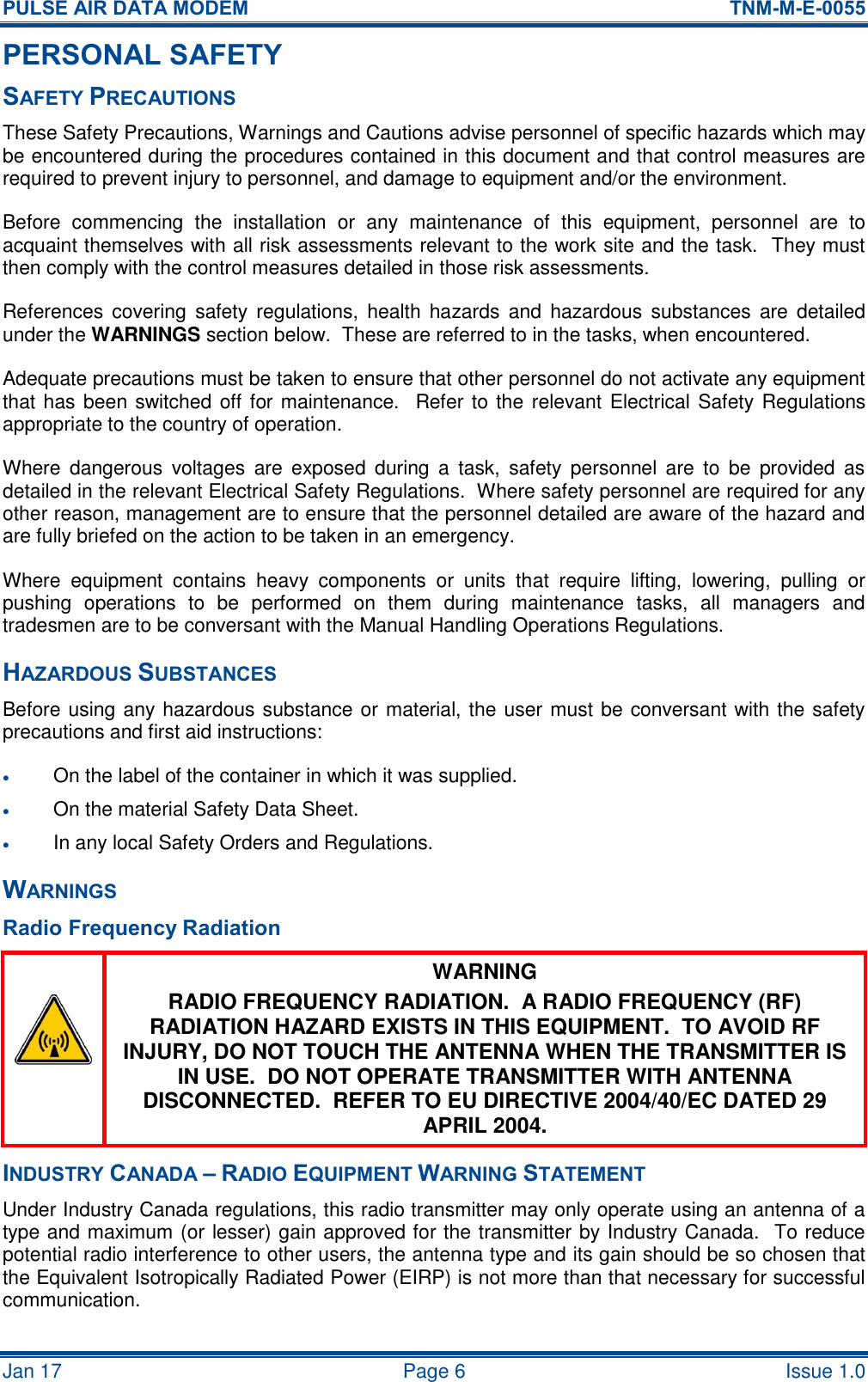
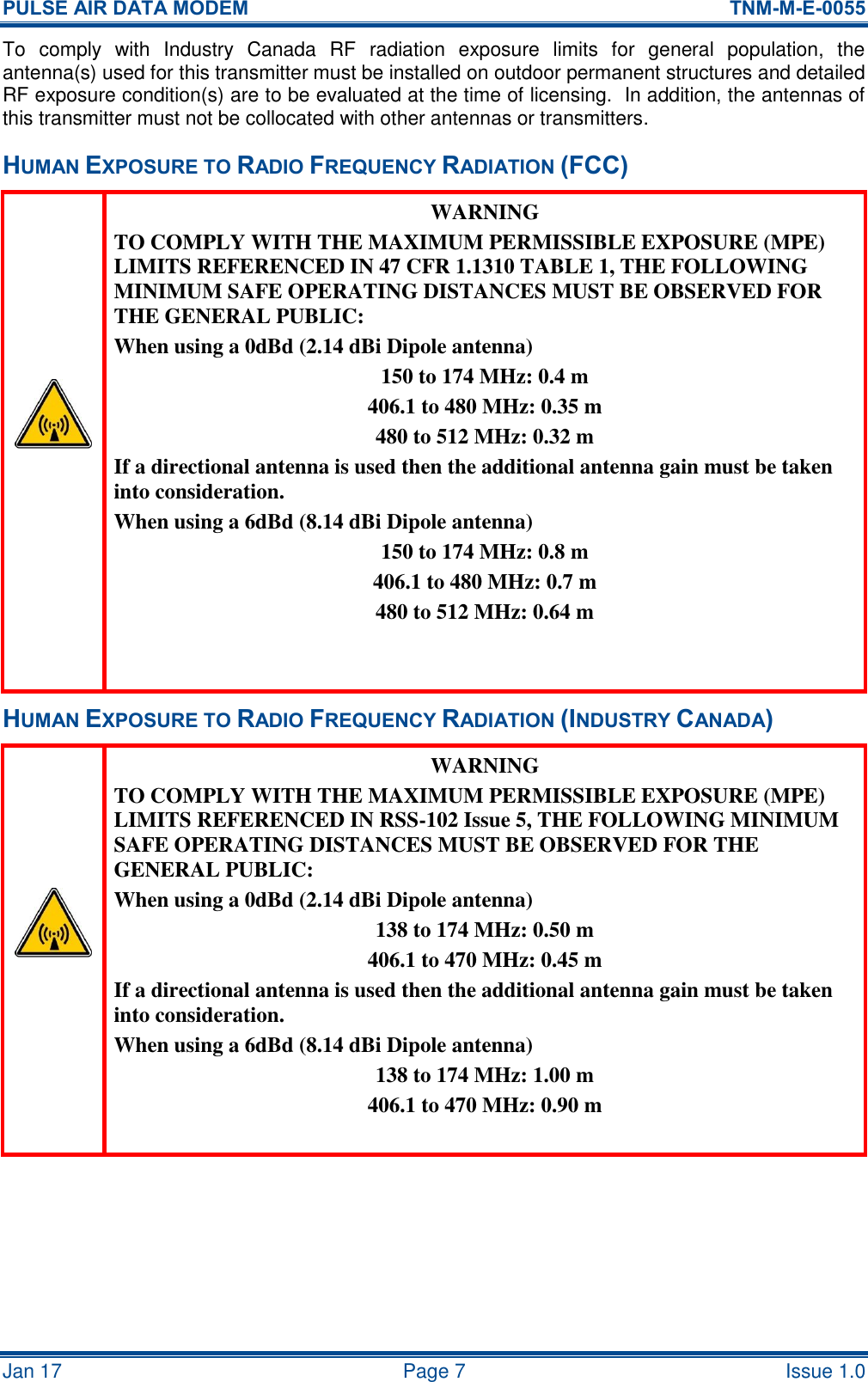
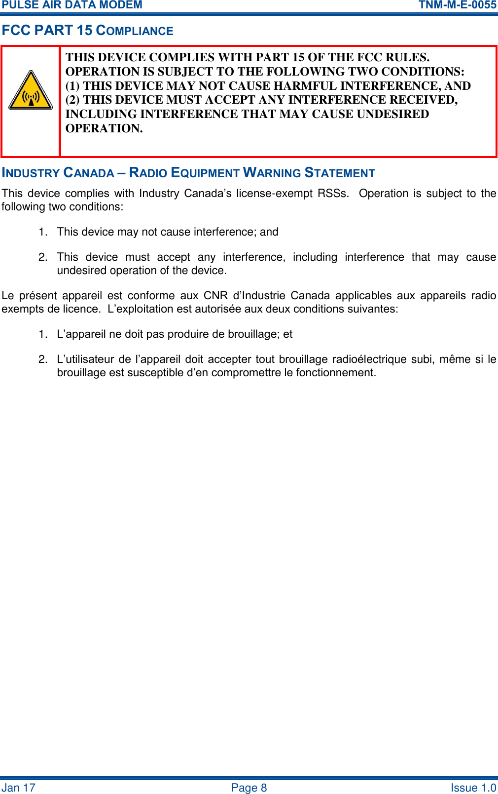
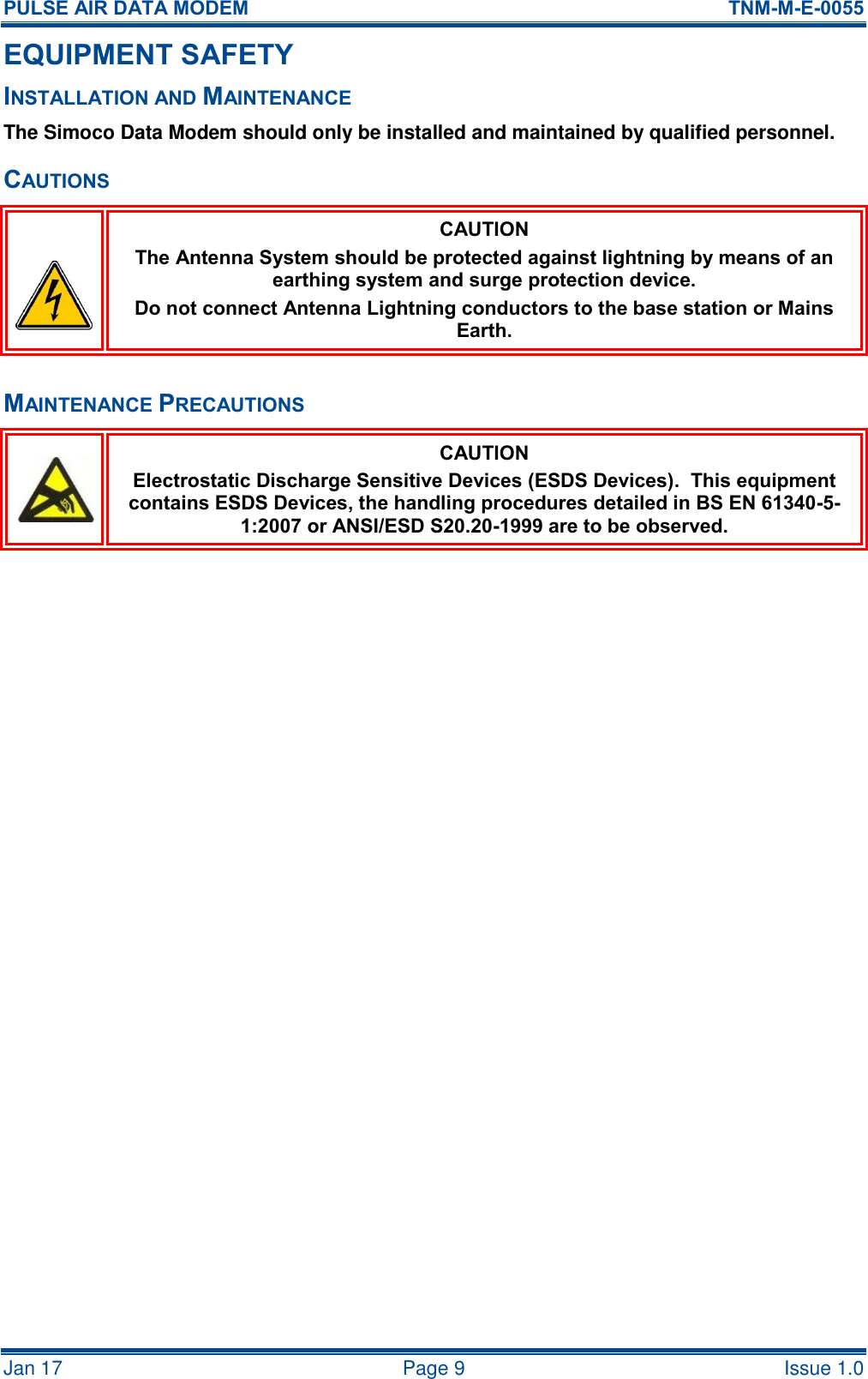
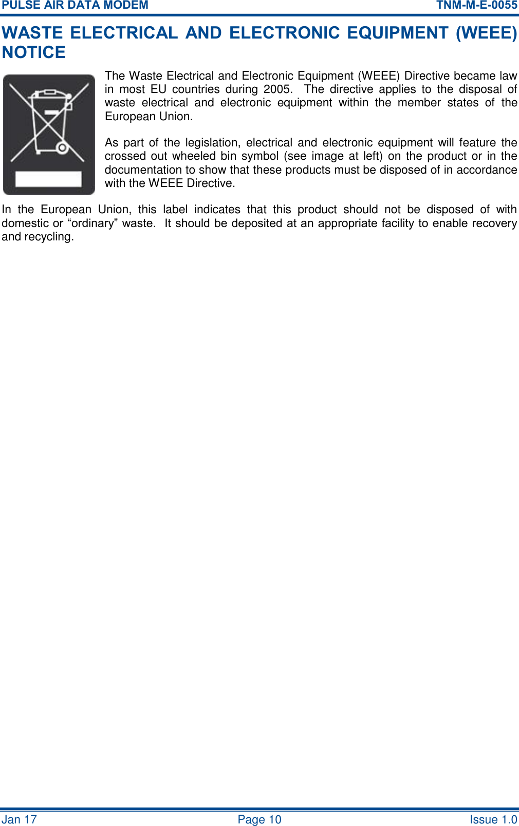
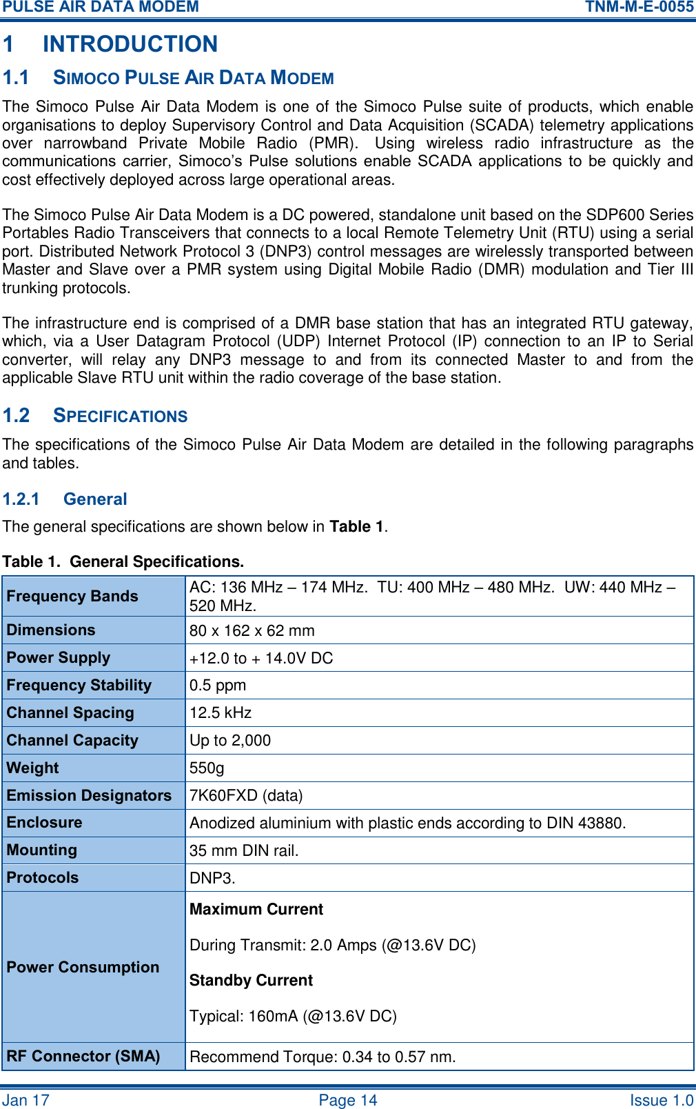
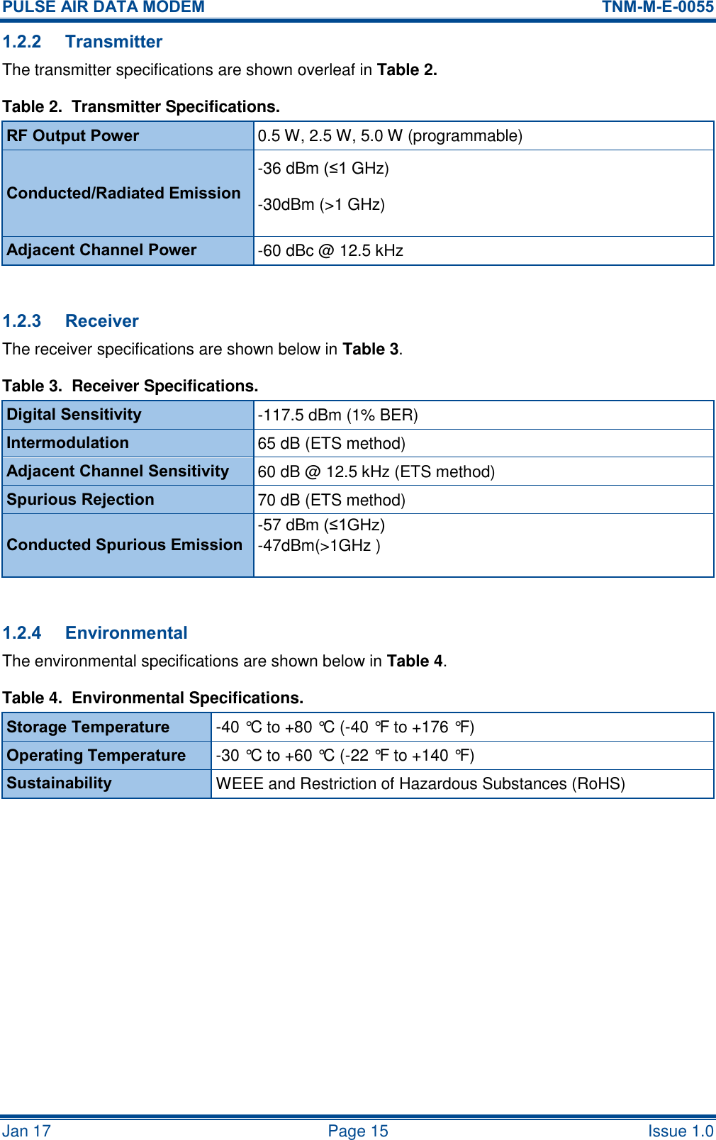
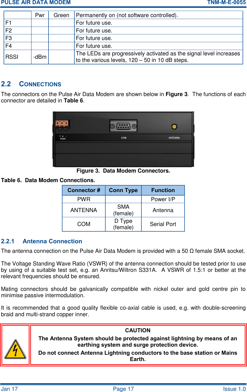
![PULSE AIR DATA MODEM TNM-M-E-0055 Jan 17 Page 16 Issue 1.0 2 DESCRIPTION The Pulse Air Data Modem consists of three main Printed Circuit Boards (PCBs), these are: the RTU Modem Interface PCB; the Light Emitting Diode (LED) Display PCB; and the SDD690 Radio PCB based on the SDP600 Series Portable Radio. See the SDP600 Series DMR Portable Radio Transceiver – Service Manual[1] for more information. A simple block diagram of the Pulse Air Data Modem is shown below in Figure 1. Figure 1. Data Modem Simple Block Diagram. A block diagram of the Interface PCB is shown below in Figure 2. Figure 2. Interface PCB Block Diagram. 2.1 LED INDICATIONS On the front of the Data Modem there are several LED indicators. There details are explained below in Table 5. Table 5. Details LED Indicators. Legend Colour Description Radio Tx Activated for ~500 ms when radio is transmitting. Rx Activated for ~500 ms when radio is receiving. Com Tx Activated for min ~200 ms when serial data is input to the modem. Rx Activated for min ~200 ms when serial data is output from the modem. System OK Green Active (ON) when the radio is in its operational mode and has service. OFF when in FPP, error states, or not in service. VoltageRegulatorU15V0Regulator 2V8RegulatorRS232Driver2V8 to 5V0LevelShifterLED PCBSDD690Radio Modem Engine12V - 14VDC In 8V08V0 2V85V05V05V0Serial2V8 I C25V0 I C2IC2VINIC2O/P to9-wayD TypeO/Ps toLEDs5V0LEDDisplay BoardSDD690Radio Modem EngineRTU ModemInterface PCBIC2V82TTLSerial 8V0SupplyIC5 V25 V SupplyAntennaRS232Serial12 - 14 VSupply](https://usermanual.wiki/Simoco-Wireless-Solutions/AIR600AC/User-Guide-3299009-Page-16.png)