Simoco Wireless Solutions AIR600AC VHF Fixed Station Remote Telemetry Transceiver User Manual
Simoco Australasia Pty Ltd VHF Fixed Station Remote Telemetry Transceiver
User Manual

PULSE AIR DATA MODEM
USER and INSTALLATION MANUAL
TNM-M-E-0055, Issue 1.0
January 2017
© Simoco 2017
Field House,
Uttoxeter Old Road
Derby
DE1 1NH
Tel: +44 (0) 1332 375500
Fax: +44 (0) 1332 375501
http://www.simocogroup.com
1270 Ferntree Gully Road,
Scoresby
Victoria, 3179
Australia
Tel: +61 (0)3 9730 3999
Fax: +61 (0)3 9730 3988
http://www.simocogroup.com

PULSE AIR DATA MODEM TNM-M-E-0055
Jan 17 Page 2 Issue 1.0
PREFACE
DECLARATION
This User and Installation Manual covers the Pulse Air Data Modem.
Any performance figures quoted are subject to normal manufacturing and service tolerances. The
right is reserved to alter the equipment described in this manual in the light of future technical
development.
Changes or modifications not expressly approved by the party responsible for compliance could
void the user’s authority to operate the equipment.
NOTE.
The manufacturer is not responsible for any radio or television interference caused by
unauthorized modifications to this equipment. Such modifications could void the
user’s authority to operate the equipment.
COPYRIGHT
All information contained in this document is the property of Simoco. All rights are reserved. This
document may not, in whole or in part, be copied, photocopied, reproduced, translated, stored, or
reduced to any electronic medium or machine-readable form, without prior written permission from
Simoco.
DISCLAIMER
There are no warranties extended or granted by this document. Simoco accepts no responsibility
for damage arising from use of the information contained in the document or of the equipment and
software it describes. It is the responsibility of the user to ensure that use of such information,
equipment and software complies with the laws, rules and regulations of the applicable
jurisdictions.
EQUIPMENT AND MANUAL UPDATES
In the interests of improving the performance, reliability or servicing of the equipment, Simoco
reserves the right to update the equipment or this document or both without prior notice.
ERRORS AND OMISSIONS
The usefulness of this publication depends upon the accuracy and completeness of the information
contained within it. Whilst every endeavour has been made to eliminate any errors, some may still
exist. It is requested that any errors or omissions noted should be reported to either of the
following who are part of the Simoco group:
Field House,
Uttoxeter Old Road
Derby
DE1 1NH
Tel: +44 (0) 1332 375500
Fax: +44 (0) 1332 375501
http://www.simocogroup.com
1270 Ferntree Gully Road,
Scoresby
Victoria, 3179
Australia
Tel: +61 (0)3 9730 3999
Fax: +61 (0)3 9730 3988
http://www.simocogroup.com

PULSE AIR DATA MODEM TNM-M-E-0055
Jan 17 Page 3 Issue 1.0
DOCUMENT HISTORY
Issue
Date
Comments
1.0
January 2017
First Issue.
RELATED DOCUMENTS
1. TNM-M-E-0033. SDP600 Series DMR Portable Radio Transceiver – Service Manual.
2. TNM-U-E-0112_SDMT User Manual.
To order printed copies of this or any of the above publications, please contact Simoco. See the
Support page for contact information.
A comprehensive list of documentation is available for download on the Simoco website
http://www.simocogroup.com via the Partner Portal.

PULSE AIR DATA MODEM TNM-M-E-0055
Jan 17 Page 4 Issue 1.0
TABLE OF CONTENTS
Page
Title Page ...................................................................................................................................... 1
Preface .......................................................................................................................................... 2
Table of Contents (this list) ......................................................................................................... 4
List of Figures .............................................................................................................................. 5
List of Tables ................................................................................................................................ 5
PERSONAL SAFETY .................................................................................................................... 6
EQUIPMENT SAFETY ................................................................................................................... 9
WEEE Notice .............................................................................................................................. 10
Simoco Support ......................................................................................................................... 11
Abbreviations ............................................................................................................................. 13
1 INTRODUCTION ................................................................................................................. 14
1.1 SIMOCO PULSE AIR DATA MODEM ..................................................................................... 14
1.2 SPECIFICATIONS ............................................................................................................... 14
1.2.1 General .................................................................................................................. 14
1.2.2 Transmitter ............................................................................................................. 15
1.2.3 Receiver ................................................................................................................. 15
1.2.4 Environmental ........................................................................................................ 15
2 DESCRIPTION .................................................................................................................... 16
2.1 LED INDICATIONS ............................................................................................................. 16
2.2 CONNECTIONS .................................................................................................................. 17
2.2.1 Antenna Connection ............................................................................................... 17
2.2.2 Power Connection .................................................................................................. 18
2.2.3 COM Serial Port ..................................................................................................... 18
2.2.4 LED Indications ...................................................................................................... 19
3 MAINTENANCE .................................................................................................................. 20
3.1 INSTALLATION INSTRUCTIONS ............................................................................................ 20
3.1.1 Install Using User Provided Cables and Materials .................................................. 20
3.2 SYSTEM CONFIGURATION AND COMMISSIONING PROCEDURE .............................................. 20
4 SPARES .............................................................................................................................. 21
4.1 SERVICE CONCEPT ........................................................................................................... 21
4.2 LEVEL 2 SPARES SCHEDULE ............................................................................................. 21
4.2.1 Pulse Air Data Modem ........................................................................................... 21
4.3 WARRANTY ...................................................................................................................... 22
4.3.1 Service Within and Out Of Warranty ....................................................................... 22
4.3.2 Ancillary Items ........................................................................................................ 22
4.3.3 Unpacking Equipment ............................................................................................ 22
4.4 SOFTWARE POLICY ........................................................................................................... 22

PULSE AIR DATA MODEM TNM-M-E-0055
Jan 17 Page 5 Issue 1.0
APPENDICES
A Nil.
LIST OF FIGURES
Page
Figure 1. Data Modem Simple Block Diagram. ............................................................................. 16
Figure 2. Interface PCB Block Diagram. ....................................................................................... 16
Figure 3. Data Modem Connectors. ............................................................................................. 17
LIST OF TABLES
Page
Table 1. General Specifications. .................................................................................................. 14
Table 2. Transmitter Specifications. ............................................................................................. 15
Table 3. Receiver Specifications. ................................................................................................. 15
Table 4. Environmental Specifications. ........................................................................................ 15
Table 5. Details LED Indicators. ................................................................................................... 16
Table 6. Data Modem Connections. ............................................................................................. 17
Table 7. DC Power Connector Pin-outs. ...................................................................................... 18
Table 8. COM Serial Port Connector Pin-outs. ............................................................................. 18
Table 9. Details of LED Indications. ............................................................................................. 19
Table 10. Service Levels. ............................................................................................................. 21
Table 11. Service Level 2 Parts List. ............................................................................................ 21

PULSE AIR DATA MODEM TNM-M-E-0055
Jan 17 Page 6 Issue 1.0
PERSONAL SAFETY
SAFETY PRECAUTIONS
These Safety Precautions, Warnings and Cautions advise personnel of specific hazards which may
be encountered during the procedures contained in this document and that control measures are
required to prevent injury to personnel, and damage to equipment and/or the environment.
Before commencing the installation or any maintenance of this equipment, personnel are to
acquaint themselves with all risk assessments relevant to the work site and the task. They must
then comply with the control measures detailed in those risk assessments.
References covering safety regulations, health hazards and hazardous substances are detailed
under the WARNINGS section below. These are referred to in the tasks, when encountered.
Adequate precautions must be taken to ensure that other personnel do not activate any equipment
that has been switched off for maintenance. Refer to the relevant Electrical Safety Regulations
appropriate to the country of operation.
Where dangerous voltages are exposed during a task, safety personnel are to be provided as
detailed in the relevant Electrical Safety Regulations. Where safety personnel are required for any
other reason, management are to ensure that the personnel detailed are aware of the hazard and
are fully briefed on the action to be taken in an emergency.
Where equipment contains heavy components or units that require lifting, lowering, pulling or
pushing operations to be performed on them during maintenance tasks, all managers and
tradesmen are to be conversant with the Manual Handling Operations Regulations.
HAZARDOUS SUBSTANCES
Before using any hazardous substance or material, the user must be conversant with the safety
precautions and first aid instructions:
On the label of the container in which it was supplied.
On the material Safety Data Sheet.
In any local Safety Orders and Regulations.
WARNINGS
Radio Frequency Radiation
WARNING
RADIO FREQUENCY RADIATION. A RADIO FREQUENCY (RF)
RADIATION HAZARD EXISTS IN THIS EQUIPMENT. TO AVOID RF
INJURY, DO NOT TOUCH THE ANTENNA WHEN THE TRANSMITTER IS
IN USE. DO NOT OPERATE TRANSMITTER WITH ANTENNA
DISCONNECTED. REFER TO EU DIRECTIVE 2004/40/EC DATED 29
APRIL 2004.
INDUSTRY CANADA – RADIO EQUIPMENT WARNING STATEMENT
Under Industry Canada regulations, this radio transmitter may only operate using an antenna of a
type and maximum (or lesser) gain approved for the transmitter by Industry Canada. To reduce
potential radio interference to other users, the antenna type and its gain should be so chosen that
the Equivalent Isotropically Radiated Power (EIRP) is not more than that necessary for successful
communication.
PULSE AIR DATA MODEM TNM-M-E-0055
Jan 17 Page 7 Issue 1.0
To comply with Industry Canada RF radiation exposure limits for general population, the
antenna(s) used for this transmitter must be installed on outdoor permanent structures and detailed
RF exposure condition(s) are to be evaluated at the time of licensing. In addition, the antennas of
this transmitter must not be collocated with other antennas or transmitters.
HUMAN EXPOSURE TO RADIO FREQUENCY RADIATION (FCC)
WARNING
TO COMPLY WITH THE MAXIMUM PERMISSIBLE EXPOSURE (MPE)
LIMITS REFERENCED IN 47 CFR 1.1310 TABLE 1, THE FOLLOWING
MINIMUM SAFE OPERATING DISTANCES MUST BE OBSERVED FOR
THE GENERAL PUBLIC:
When using a 0dBd (2.14 dBi Dipole antenna)
150 to 174 MHz: 0.4 m
406.1 to 480 MHz: 0.35 m
480 to 512 MHz: 0.32 m
If a directional antenna is used then the additional antenna gain must be taken
into consideration.
When using a 6dBd (8.14 dBi Dipole antenna)
150 to 174 MHz: 0.8 m
406.1 to 480 MHz: 0.7 m
480 to 512 MHz: 0.64 m
HUMAN EXPOSURE TO RADIO FREQUENCY RADIATION (INDUSTRY CANADA)
WARNING
TO COMPLY WITH THE MAXIMUM PERMISSIBLE EXPOSURE (MPE)
LIMITS REFERENCED IN RSS-102 Issue 5, THE FOLLOWING MINIMUM
SAFE OPERATING DISTANCES MUST BE OBSERVED FOR THE
GENERAL PUBLIC:
When using a 0dBd (2.14 dBi Dipole antenna)
138 to 174 MHz: 0.50 m
406.1 to 470 MHz: 0.45 m
If a directional antenna is used then the additional antenna gain must be taken
into consideration.
When using a 6dBd (8.14 dBi Dipole antenna)
138 to 174 MHz: 1.00 m
406.1 to 470 MHz: 0.90 m

PULSE AIR DATA MODEM TNM-M-E-0055
Jan 17 Page 8 Issue 1.0
FCC PART 15 COMPLIANCE
THIS DEVICE COMPLIES WITH PART 15 OF THE FCC RULES.
OPERATION IS SUBJECT TO THE FOLLOWING TWO CONDITIONS:
(1) THIS DEVICE MAY NOT CAUSE HARMFUL INTERFERENCE, AND
(2) THIS DEVICE MUST ACCEPT ANY INTERFERENCE RECEIVED,
INCLUDING INTERFERENCE THAT MAY CAUSE UNDESIRED
OPERATION.
INDUSTRY CANADA – RADIO EQUIPMENT WARNING STATEMENT
This device complies with Industry Canada’s license-exempt RSSs. Operation is subject to the
following two conditions:
1. This device may not cause interference; and
2. This device must accept any interference, including interference that may cause
undesired operation of the device.
Le présent appareil est conforme aux CNR d’Industrie Canada applicables aux appareils radio
exempts de licence. L’exploitation est autorisée aux deux conditions suivantes:
1. L’appareil ne doit pas produire de brouillage; et
2. L’utilisateur de l’appareil doit accepter tout brouillage radioélectrique subi, même si le
brouillage est susceptible d’en compromettre le fonctionnement.
PULSE AIR DATA MODEM TNM-M-E-0055
Jan 17 Page 9 Issue 1.0
EQUIPMENT SAFETY
INSTALLATION AND MAINTENANCE
The Simoco Data Modem should only be installed and maintained by qualified personnel.
CAUTIONS
CAUTION
The Antenna System should be protected against lightning by means of an
earthing system and surge protection device.
Do not connect Antenna Lightning conductors to the base station or Mains
Earth.
MAINTENANCE PRECAUTIONS
CAUTION
Electrostatic Discharge Sensitive Devices (ESDS Devices). This equipment
contains ESDS Devices, the handling procedures detailed in BS EN 61340-5-
1:2007 or ANSI/ESD S20.20-1999 are to be observed.

PULSE AIR DATA MODEM TNM-M-E-0055
Jan 17 Page 10 Issue 1.0
WASTE ELECTRICAL AND ELECTRONIC EQUIPMENT (WEEE)
NOTICE
The Waste Electrical and Electronic Equipment (WEEE) Directive became law
in most EU countries during 2005. The directive applies to the disposal of
waste electrical and electronic equipment within the member states of the
European Union.
As part of the legislation, electrical and electronic equipment will feature the
crossed out wheeled bin symbol (see image at left) on the product or in the
documentation to show that these products must be disposed of in accordance
with the WEEE Directive.
In the European Union, this label indicates that this product should not be disposed of with
domestic or “ordinary” waste. It should be deposited at an appropriate facility to enable recovery
and recycling.

PULSE AIR DATA MODEM TNM-M-E-0055
Jan 17 Page 11 Issue 1.0
SIMOCO SUPPORT
CONTACT INFORMATION
At Simoco we welcome your comments, feedback and suggestions. Departmental contacts have
been provided for your quick reference below.
UK Customer Services
Email: customer.service@simocogroup.com
Tel: UK: 08717 411 050
International: +44 (0) 1332 375 671
Fax: UK: 08717 411 049
International: +44 (0) 1332 376 672
Sales
E-mail: sales@simocogroup.com
Marketing
E-mail: marketing@simocogroup.com
Australian Customer Services
Email: inquiry.aus@simocogroup.com
Tel: Within Australia: 1300 363 607
International: +61 3 9730 3999
US Customer Services
Email: customerservice@simocogroup.com
TECHNICAL SUPPORT
In order to streamline support requests and better serve our customers, at Simoco we utilize a
support ticket system. Every support request is assigned a unique ticket number, which customers
can use to track the progress and responses online. For reference, Simoco provide complete
archives and history of all customer support requests. In order to use the support ticket system, a
valid email address is required.
A link to the online Simoco Group Support Centre Ticket Tracking system is provided below:
http://www.simocogroup.com/ticket/supportcentre.htm
If you still require further technical assistance after raising a support ticket, please contact us via
the email addresses or via the Technical Support Helpline numbers below.
Technical Support Email Addresses
Simoco EMEA: techsupport@simocogroup.com
Simoco Australasia: inquiry.aus@simocogroup.com


PULSE AIR DATA MODEM TNM-M-E-0055
Jan 17 Page 13 Issue 1.0
ABBREVIATIONS
The following abbreviations are used throughout this document. Wherever practicable, whenever
the abbreviation is first used, the full meaning is given with the abbreviation in parenthesis, after
that only the abbreviation will be used.
Abbreviation
Meaning
AMBE
Advanced Multi Band Excitation
Com
Communication
DC
Direct Current
DIN
Deutches Institut für Normung
DMR
Digital Mobile Radio
DNP3
Distributed Network Protocol 3
FM
Frequency Modulation
FPP
Field Personality Programmer
I2C
Inter-Integrated Circuit
ID
Identification
I/O
Input/Output
IP
Internet Protocol
IP(2)
Ingress Protection
LED
Light Emitting Diode
NC
Not Connected
PC
Personal Computer
PCB
Printed Circuit Board
PMR
Private Mobile Radio
RF
Radio Frequency
RSSI
Received Signal Strength Indication
RTU
Radio Telemetry Unit
Rx
Receiver, Receive
SCADA
Supervisory Control And Data Acquisition
SDMT
Simoco Digital Management Terminal
SDP
Simoco Digital Portable
SMA
SubMiniature version A
SQL
Structured Query Language
TBD
To Be Detailed
Tx
Transmitter, Transmit
UDP
User Datagram Protocol
USB
Universal Serial Bus
VAC
Virtual Area Controller
VSWR
Voltage Standing Wave Ratio

PULSE AIR DATA MODEM TNM-M-E-0055
Jan 17 Page 14 Issue 1.0
1 INTRODUCTION
1.1 SIMOCO PULSE AIR DATA MODEM
The Simoco Pulse Air Data Modem is one of the Simoco Pulse suite of products, which enable
organisations to deploy Supervisory Control and Data Acquisition (SCADA) telemetry applications
over narrowband Private Mobile Radio (PMR). Using wireless radio infrastructure as the
communications carrier, Simoco’s Pulse solutions enable SCADA applications to be quickly and
cost effectively deployed across large operational areas.
The Simoco Pulse Air Data Modem is a DC powered, standalone unit based on the SDP600 Series
Portables Radio Transceivers that connects to a local Remote Telemetry Unit (RTU) using a serial
port. Distributed Network Protocol 3 (DNP3) control messages are wirelessly transported between
Master and Slave over a PMR system using Digital Mobile Radio (DMR) modulation and Tier III
trunking protocols.
The infrastructure end is comprised of a DMR base station that has an integrated RTU gateway,
which, via a User Datagram Protocol (UDP) Internet Protocol (IP) connection to an IP to Serial
converter, will relay any DNP3 message to and from its connected Master to and from the
applicable Slave RTU unit within the radio coverage of the base station.
1.2 SPECIFICATIONS
The specifications of the Simoco Pulse Air Data Modem are detailed in the following paragraphs
and tables.
1.2.1 General
The general specifications are shown below in Table 1.
Table 1. General Specifications.
Frequency Bands
AC: 136 MHz – 174 MHz. TU: 400 MHz – 480 MHz. UW: 440 MHz –
520 MHz.
Dimensions
80 x 162 x 62 mm
Power Supply
+12.0 to + 14.0V DC
Frequency Stability
0.5 ppm
Channel Spacing
12.5 kHz
Channel Capacity
Up to 2,000
Weight
550g
Emission Designators
7K60FXD (data)
Enclosure
Anodized aluminium with plastic ends according to DIN 43880.
Mounting
35 mm DIN rail.
Protocols
DNP3.
Power Consumption
Maximum Current
During Transmit: 2.0 Amps (@13.6V DC)
Standby Current
Typical: 160mA (@13.6V DC)
RF Connector (SMA)
Recommend Torque: 0.34 to 0.57 nm.

PULSE AIR DATA MODEM TNM-M-E-0055
Jan 17 Page 15 Issue 1.0
1.2.2 Transmitter
The transmitter specifications are shown overleaf in Table 2.
Table 2. Transmitter Specifications.
RF Output Power
0.5 W, 2.5 W, 5.0 W (programmable)
Conducted/Radiated Emission
-36 dBm (≤1 GHz)
-30dBm (>1 GHz)
Adjacent Channel Power
-60 dBc @ 12.5 kHz
1.2.3 Receiver
The receiver specifications are shown below in Table 3.
Table 3. Receiver Specifications.
Digital Sensitivity
-117.5 dBm (1% BER)
Intermodulation
65 dB (ETS method)
Adjacent Channel Sensitivity
60 dB @ 12.5 kHz (ETS method)
Spurious Rejection
70 dB (ETS method)
Conducted Spurious Emission
-57 dBm (≤1GHz)
-47dBm(>1GHz )
1.2.4 Environmental
The environmental specifications are shown below in Table 4.
Table 4. Environmental Specifications.
Storage Temperature
-40 °C to +80 °C (-40 °F to +176 °F)
Operating Temperature
-30 °C to +60 °C (-22 °F to +140 °F)
Sustainability
WEEE and Restriction of Hazardous Substances (RoHS)
PULSE AIR DATA MODEM TNM-M-E-0055
Jan 17 Page 16 Issue 1.0
2 DESCRIPTION
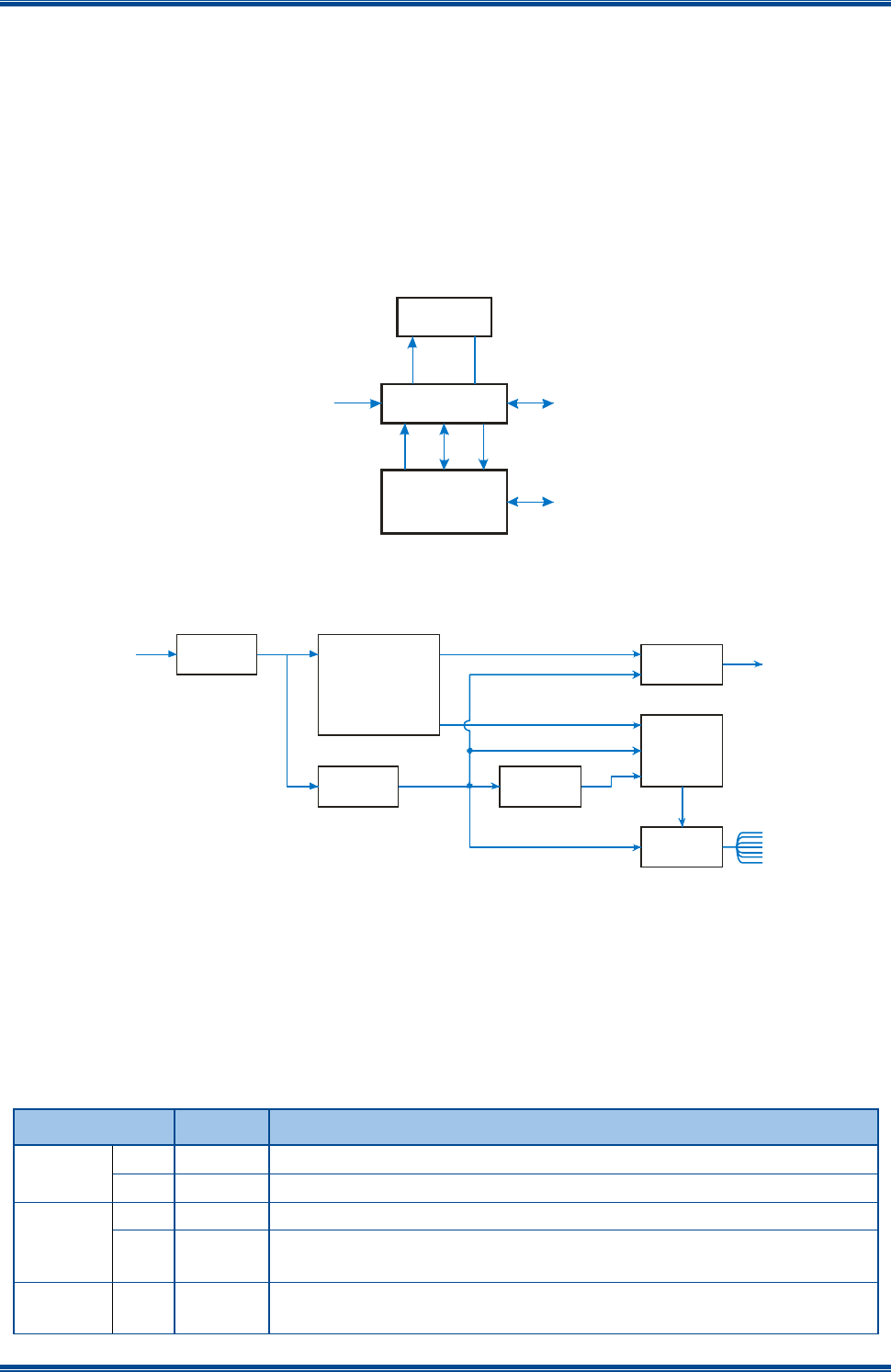
The Pulse Air Data Modem consists of three main Printed Circuit Boards (PCBs), these are:
the RTU Modem Interface PCB;
the Light Emitting Diode (LED) Display PCB; and
the SDD690 Radio PCB based on the SDP600 Series Portable Radio. See the SDP600
Series DMR Portable Radio Transceiver – Service Manual[1] for more information.
A simple block diagram of the Pulse Air Data Modem is shown below in Figure 1.
Figure 1. Data Modem Simple Block Diagram.
A block diagram of the Interface PCB is shown below in Figure 2.
Figure 2. Interface PCB Block Diagram.
2.1 LED INDICATIONS
On the front of the Data Modem there are several LED indicators. There details are explained
below in Table 5.
Table 5. Details LED Indicators.
Legend
Colour
Description
Radio
Tx
Activated for ~500 ms when radio is transmitting.
Rx
Activated for ~500 ms when radio is receiving.
Com
Tx
Activated for min ~200 ms when serial data is input to the modem.
Rx
Activated for min ~200 ms when serial data is output from the
modem.
System
OK
Green
Active (ON) when the radio is in its operational mode and has
service. OFF when in FPP, error states, or not in service.
Voltage
Regulator
U1
5V0
Regulator 2V8
Regulator
RS232
Driver
2V8 to 5V0
Level
Shifter
LED PCB
SDD690
Radio Modem Engine
12V - 14V
DC In 8V0
8V0 2V8
5V0
5V0
5V0
Serial
2V8 I C
2
5V0 I C
2
IC
2
VIN
IC
2
O/P to
9-way
D Type
O/Ps to
LEDs
5V0
LED
Display Board
SDD690
Radio Modem Engine
RTU Modem
Interface PCB
IC
2V8
2TTL
Serial 8V0
Supply
IC
5 V
25 V Supply
Antenna
RS232
Serial
12 - 14 V
Supply
PULSE AIR DATA MODEM TNM-M-E-0055
Jan 17 Page 17 Issue 1.0
Pwr
Green
Permanently on (not software controlled).
F1
For future use.
F2
For future use.
F3
For future use.
F4
For future use.
RSSI
-dBm
The LEDs are progressively activated as the signal level increases
to the various levels, 120 – 50 in 10 dB steps.
2.2 CONNECTIONS
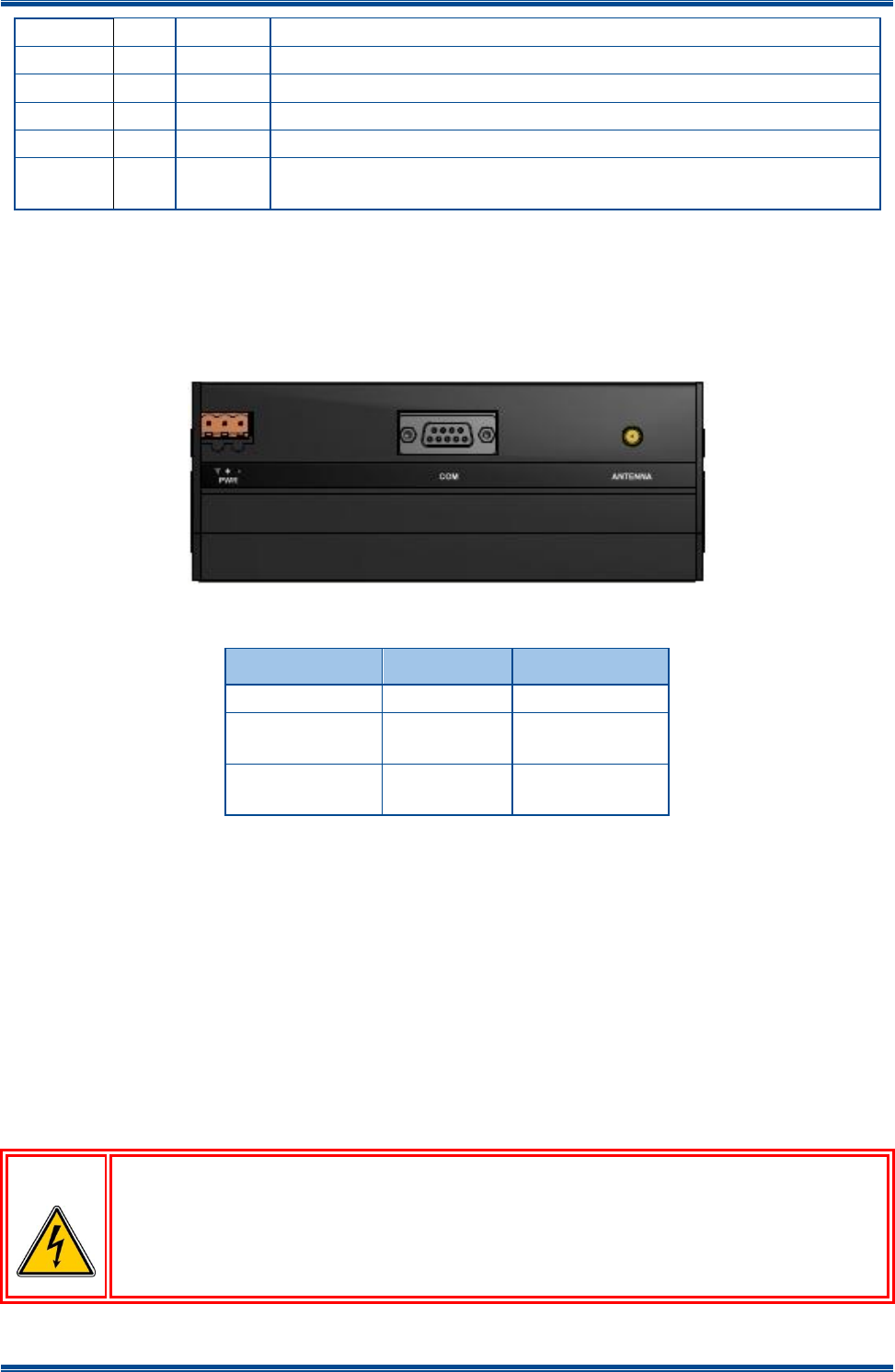
The connectors on the Pulse Air Data Modem are shown below in Figure 3. The functions of each
connector are detailed in Table 6.
Figure 3. Data Modem Connectors.
Table 6. Data Modem Connections.
Connector #
Conn Type
Function
PWR
Power I/P
ANTENNA
SMA
(female)
Antenna
COM
D Type
(female)
Serial Port
2.2.1 Antenna Connection
The antenna connection on the Pulse Air Data Modem is provided with a 50 Ω female SMA socket.
The Voltage Standing Wave Ratio (VSWR) of the antenna connection should be tested prior to use
by using of a suitable test set, e.g. an Anritsu/Wiltron S331A. A VSWR of 1.5:1 or better at the
relevant frequencies should be ensured.
Mating connectors should be galvanically compatible with nickel outer and gold centre pin to
minimise passive intermodulation.
It is recommended that a good quality flexible co-axial cable is used, e.g. with double-screening
braid and multi-strand copper inner.
CAUTION
The Antenna System should be protected against lightning by means of an
earthing system and surge protection device.
Do not connect Antenna Lightning conductors to the base station or Mains
Earth.
PULSE AIR DATA MODEM TNM-M-E-0055
Jan 17 Page 18 Issue 1.0
2.2.2 Power Connection
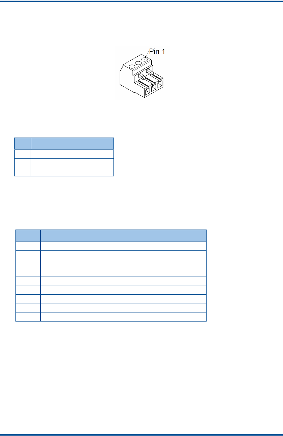
The DC power input is via a 3-way screw terminal connector (Weidmuller Onimate Signal – series
BLA/SLA 5.08). The three pins are wired to suit the voltage range shown in Table 7 below. Pin 1
of the 3-way screw connector is shown in Figure 4 below.
Figure 4: Pin 1 of the 3-way screw connector
Table 7. DC Power Connector Pin-outs.
Pin
Description
1
0V
2
+12.0 to +14.0 V
3
Not Connected
The equipment must be installed so that the power socket is readily accessible.
2.2.3 COM Serial Port
The connector pin-outs for the 9-way D Type ‘COM’ Serial Port are shown below in Table 8.
Table 8. COM Serial Port Connector Pin-outs.
Pin
Function
1
Data Carrier Detect (DCD). Connected to pin 4 and 6
2
Tx 1
3
Rx 1
4
Data Terminal Ready (DTR). Connected to pin 1 and 6
5
0 V
6
Data Set Ready (DSR). Connected to pin 1 and 4
7
NC
8
NC
9
NC

PULSE AIR DATA MODEM TNM-M-E-0055
Jan 17 Page 19 Issue 1.0
2.2.4 LED Indications
Table 9. Details of LED Indications.
LED
Details
System
Pwr
Permanently on (not software controlled).
OK
Active (ON) when the radio is in its operational mode and has service. OFF
when in FPP or error states.
Com
Tx
Activated for min ~200 ms when serial data is input to the modem.
Rx
Activated for min ~200 ms when serial data is output from the modem.
RSSI
The LEDs are progressively activated as the signal level increases to the
various levels. The ‘L’ LED is calibrated for -115 dBm, the lowest useful
sensitivity for data comms.

PULSE AIR DATA MODEM TNM-M-E-0055
Jan 17 Page 20 Issue 1.0
3 MAINTENANCE
3.1 INSTALLATION INSTRUCTIONS
3.1.1 Install Using User Provided Cables and Materials
To install the Pulse Air Data Modem in your system, carry out the following:
1. Clip the Data Modem to a suitable DIN rail.
1.1. Using a suitable test set, e.g. an Anritsu/Wiltron S331A, check the antenna connection
for a VSWR of 1.5:1 or better at the relevant frequencies.
2. On the Data Modem, carry out the following:
2.1. Using a suitable serial communications cable, connect the ‘COM’ socket to the relevant
serial connection on your system.
2.2. Using a suitable co-axial cable, connect the ‘ANTENNA’ socket to the antenna.
2.3. Using a suitable DC Power Cable, connect the ‘PWR’ socket to a suitable DC power
source. Take care to observe the correct polarity and supply voltages.
3.2 SYSTEM CONFIGURATION AND COMMISSIONING PROCEDURE
Please see the Pulse Air System and Configuration Commissioning guide for the full sequence of
operations for commissioning all new Pulse Air Data Modem.

PULSE AIR DATA MODEM TNM-M-E-0055
Jan 17 Page 21 Issue 1.0
4 SPARES
4.1 SERVICE CONCEPT
It is a requirement that once the customer has purchased equipment, Simoco can follow this up by
providing an ongoing, high level of customer support together with a competitive and professional
servicing activity.
There are three levels of service available, these are detailed in Table 10 below.
Table 10. Service Levels.
Level
Activity
Recommended
Spares
Recommended Test
Equipment and Tools
1
This is intended to achieve rapid
turnaround by:
Complete replacement of the
Pulse Air Data Modem.
Reprogramming.
Faulty units are to be returned to a
Level 2 service facility with an
attached fault report.
This level of service should not
exceed 20 minutes.
Spare Pulse Air Data
Modem.
PC with Programmer (FPP).
Suitable Serial Cable.
2
Level 2 service includes Level 1 with
the addition of fault rectification by:
Replacement of PCB, mechanical
component, or cable assembly.
Cosmetic repair.
Listed in Level 2 Spares
Schedule.
Spare parts available to
order from Central
Spares.
As above + service aids and test
equipment.
3
Repair by PCB or mechanical
component replacement, Cosmetic
repair.
Repair of PCB to component level in
Central Repair Unit (CRU).
Listed in Level 2 Spares
Schedule.
Radio PCB components
only available to CRU.
As above + service aids and test
equipment.
4.2 LEVEL 2 SPARES SCHEDULE
4.2.1 Pulse Air Data Modem
The recommended spares schedule for Service Level 2 is shown below in Table 11.
Table 11. Service Level 2 Parts List.
Item
Part Number
Description
1
6102 350 20101
RTU Radio Modem
PCB Assembly
AC
136 – 174 MHz
6102 350 20071
TU
400 – 480 MHz
6102 350 20081
UW
440 – 520 MHz
6102 309 65101
RTU Modem LED PCB
6102 339 65092
RTU Modem Interface PCB (Lower)
6102 349 65191
RTU Modem Interface PCB (Upper)
6102 350 20701
RF Cable (SMA – MCX)
6102 330 00555
Interface Flexi
6102 310 07931
RTU Modem Case End Cap (c/w shielding)

PULSE AIR DATA MODEM TNM-M-E-0055
Jan 17 Page 22 Issue 1.0
4.3 WARRANTY
Unless superseded by specific contractual/supply agreements, the following warranty applies:
24 (twenty-four) months for transceivers from the date of supply.
4.3.1 Service Within and Out Of Warranty
Please contact our Customer Service department regarding support of either type. In some
countries a local Simoco agent may be responsible for providing this service. See the Support
page for contact details.
4.3.2 Ancillary Items
Please contact our Customer Service department regarding service, for replacement of these
parts. See the Support page for contact details.
4.3.3 Unpacking Equipment
Any damaged or missing parts must be notified to Simoco or their agent in writing within 10 days of
receipt.
4.4 SOFTWARE POLICY
Software provided by Simoco shall remain the Company’s property or that of its licensors and the
customer recognises the confidential nature of the rights owned by the Company.
The customer is granted a personal, non-exclusive, non-transferable limited right of use of such
software in machine-readable form in direct connection with the equipment for which it was
supplied only.
In certain circumstances, the customer may be required to enter into a separate licence agreement
and pay a licence fee, which will be negotiated at the time of the contract.
The customer undertakes not to disclose any part of the software to third parties without the
Company’s written consent, nor to copy or modify any software. The Company may, at its
discretion, carry out minor modifications to software. Major modifications may be undertaken
under a separate agreement, and will be charged separately.
All software is covered by a warranty of three months from delivery and, within this warranty
period, the Company will correct errors or defects, or at its option, arrange free-of-charge
replacement against return of defective material.
Other than in the clause above, the Company makes no representations or warranties, expressed
or implied such, by way of example, but not of limitation regarding merchantable quality or fitness
for any particular purpose, or that the software is error free, the Company does not accept liability
with respect to any claims for loss of profits or of contracts, or of any other loss of any kind
whatsoever on account of use of software and copies thereof.