Simoco Wireless Solutions
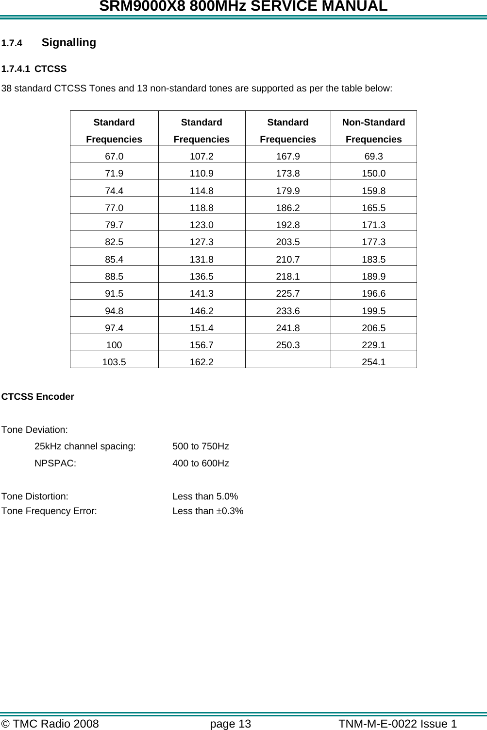
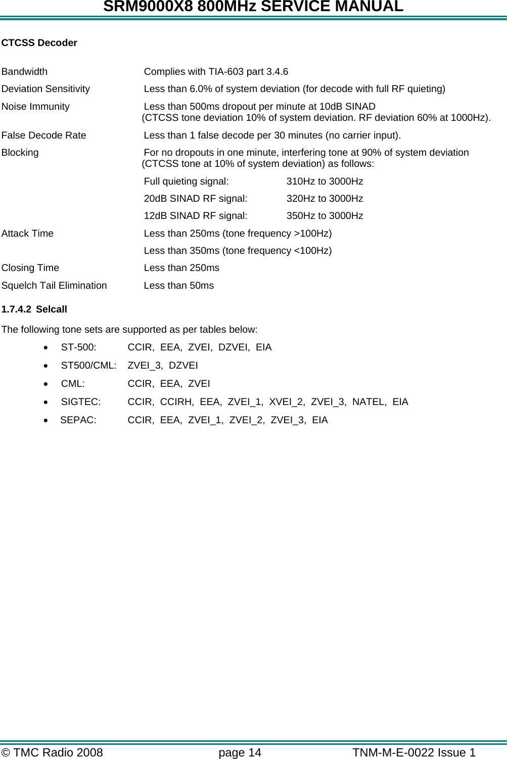
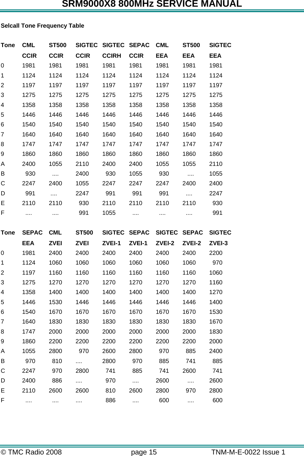
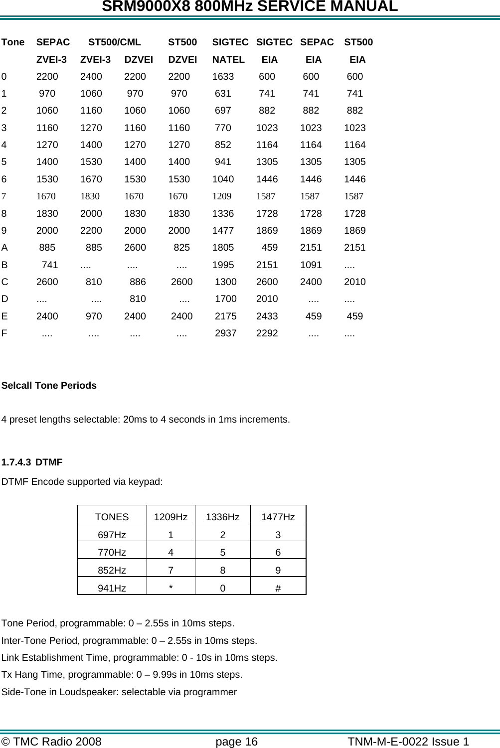
 SRM9000X8 800 MHZ ANALOGUE AND DIGITAL TRANSCEIVER User Manual USERS MANUAL

Simoco Australasia Pty Ltd 800 MHZ ANALOGUE AND DIGITAL TRANSCEIVER USERS MANUAL

USERS MANUAL

    SRM9000X8 800MHz Mobile Radio Transceiver  Revision 2 Hardware  SERVICE MANUAL   TNM-M-E-0022 ISSUE  1.0    January 2008 ISO9001 Lic.QEC20848S AI Glob al
                                 SRM9000X8 800MHz Mobile Radio Transceiver Rev 2  Hardware TNM-M-E-0022 Iss. 1.0
SRM9000X8 800MHz SERVICE MANUAL © TMC Radio 2008  page i   TNM-M-E-0022 Issue 1  TABLE OF CONTENTS APPENDICES ..............................................................................................................................................III DECLARATION .......................................................................................................................................... IV COPYRIGHT ............................................................................................................................................... IV ERRORS AND OMISSIONS....................................................................................................................... IV DOCUMENT HISTORY................................................................................................................................ V WARNINGS AND CAUTIONS.................................................................................................................... VI 1. INTRODUCTION.................................................................................................................................1 1.1 GENERAL.........................................................................................................................................1 1.2 SCOPE.............................................................................................................................................1 1.3 DESCRIPTION ...................................................................................................................................1 1.4 PRODUCT VARIANTS AND FACILITIES ................................................................................................2 1.4.1 Filename Structure ................................................................................................................4 1.4.2 Application Code ...................................................................................................................4 1.4.3 Software Type Code..............................................................................................................4 1.4.4 Version Number.....................................................................................................................6 1.4.5 Exclusions..............................................................................................................................6 1.4.6 Displaying Software Versions................................................................................................6 1.4.7 Automatic Version Upgrade Prompting.................................................................................7 1.4.8 Transceiver SW Description, Start-up and Backup-Software ...............................................8 1.4.9 Wailing Siren (Boot-up Software Corrupted).........................................................................8 1.5 ADJUSTMENT AND ALIGNMENT..........................................................................................................8 1.6 CHASSIS ASSEMBLY.........................................................................................................................9 1.6.1 Torque Settings .....................................................................................................................9 1.6.2 Thermal Compound Application............................................................................................9 1.6.3 Assembly ...............................................................................................................................9 1.7 SPECIFICATION...............................................................................................................................10 1.7.1 General................................................................................................................................10 1.7.2 Transmitter...........................................................................................................................11 1.7.3 Receiver...............................................................................................................................12 1.7.4 Signalling .............................................................................................................................13 1.7.4.1 CTCSS.....................................................................................................................13 1.7.4.2 Selcall ......................................................................................................................14 1.7.4.3 DTMF.......................................................................................................................16 1.7.4.4 DCS .........................................................................................................................17 1.7.4.5 C4FM .......................................................................................................................17 1.7.5 Environmental......................................................................................................................18 2. SERVICE PHILOSOPHY..................................................................................................................19 2.1 SERVICE CONCEPT.........................................................................................................................19 2.2 WARRANTY ....................................................................................................................................19 2.2.1 Service Within and Out Of Warranty ...................................................................................19 2.3 SOFTWARE POLICY ........................................................................................................................19 3. TECHNICAL DESCRIPTION............................................................................................................21 3.1 RECEIVER ......................................................................................................................................21 3.1.1 Front End Filters and RF Amplifier ......................................................................................21 3.1.2 First Mixer and IF Section....................................................................................................21
SRM9000X8 800MHz SERVICE MANUAL © TMC Radio 2008  page ii   TNM-M-E-0022 Issue 1  3.1.3 Quadrature Demodulator.....................................................................................................21 3.1.4 Receiver Audio Processing .................................................................................................23 3.2 TRANSMITTER ................................................................................................................................23 3.2.1 Drivers and PA Stages ........................................................................................................23 3.2.2 Power Control......................................................................................................................24 3.2.3 Antenna Changeover and Harmonic Filter..........................................................................24 3.2.4 Transmitter Audio Processing .............................................................................................24 3.3 FREQUENCY SYNTHESISER .............................................................................................................26 3.3.1 General................................................................................................................................26 3.3.2 PLL ......................................................................................................................................26 3.3.3 VCOs ...................................................................................................................................26 3.3.4 Positive Bias Generator and Loop Filter..............................................................................26 3.3.5 Phase Modulator .................................................................................................................26 3.3.6 Reference Oscillators ..........................................................................................................27 3.4 CONTROL.......................................................................................................................................29 3.4.1 DSP and PLA.......................................................................................................................29 3.4.2 PLA PWM ............................................................................................................................29 3.5 MEMORY........................................................................................................................................30 3.6 POWER SUPPLIES ..........................................................................................................................32 3.6.1 Power On Function..............................................................................................................32 3.6.2 Power Supplies....................................................................................................................32 3.6.2.1 8V Regulator U900 ..................................................................................................32 3.6.2.2 5V Regulator U901 ..................................................................................................32 3.6.2.3 3.3V Regulator U912...............................................................................................32 3.6.2.4 2.5V Regulator U903...............................................................................................33 3.6.2.5 Negative and Positive High Voltage Power Supply U904E/F .................................33 3.6.2.6 Unswitched Battery (13V8_UNSW_F) ....................................................................33 4. ALIGNMENT (LEVEL 3 SERVICE ONLY).......................................................................................34 4.1 GENERAL....................................................................................................................................34 4.1.1 Test Equipment ...................................................................................................................35 4.1.2 Alignment Frequencies........................................................................................................35 4.1.3 Preset Parameters...............................................................................................................36 4.1.4 Alignment Limits ..................................................................................................................39 4.1.5 Band specific frequency limits .............................................................................................39 4.1.6 SRM9000 Radio Test Interface Unit....................................................................................39 4.1.7 Test Setup ...........................................................................................................................40 4.1.8 COMMS Setup.....................................................................................................................41 4.1.9 Band Preparation.................................................................................................................42 4.1.10 Hardware Options Select...................................................................................................42 4.1.11 Radio Preparation..............................................................................................................42 4.1.12 ALIGNMENT PROCEDURE..............................................................................................43 4.1.13 VCO DAC Alignment .........................................................................................................43 4.1.14 TCXO DAC Alignment .......................................................................................................45 4.1.15 Rx Front End DAC Alignment............................................................................................46 4.1.16 Tx Filter DAC Alignment ....................................................................................................47 4.1.17 RSSI Calibration ................................................................................................................48 4.1.18 Mute DAC Adjustment .......................................................................................................49 4.1.19 Tx Power DAC Alignment ..................................................................................................50 4.1.18    Tx Modulation DAC Alignment............................................................................................51 4.1.20 PROGRAMMING ALIGNMENT DATA..............................................................................53
SRM9000X8 800MHz SERVICE MANUAL © TMC Radio 2008  page iii   TNM-M-E-0022 Issue 1  4.1.21 CUSTOMERS RADIO PERSONALITY DATA ..................................................................53 5. REPLACEABLE PARTS..................................................................................................................54 5.1 REPLACEABLE PARTS ....................................................................................................................54 6. SCHEMATICS...................................................................................................................................55 6.1 SRM9000 800MHZ RADIO BOARD SCHEMATICS: ......................................................................55 APPENDICES APPENDIX A ~ GLOSSARY
SRM9000X8 800MHz SERVICE MANUAL © TMC Radio 2008  page iv   TNM-M-E-0022 Issue 1  Declaration The performance figures quoted are subject to normal manufacturing and service tolerances. The right is reserved to alter the equipment described in this manual in the light of future technical development.  Copyright All rights reserved. No part of this publication may be reproduced in any form or by any means without the prior permission of TMC Radio.  Errors and Omissions The usefulness of this publication depends upon the accuracy and completeness of the information contained within it. Whilst every endeavour has been made to eliminate any errors, some may still exist. It is requested that any errors or omissions noted should be reported to:  TMC Radio Pty Ltd. 1270 Ferntree Gully Road Scoresby Vic 3179 Australia  Ph: +61 3-9730-3800 (Direct: -3914) Fax: +61  3-9730-3968 Mob: +61  408-160-661  E-mail: jkuhrt@tmcradio.com www.tmcradio.com/
SRM9000X8 800MHz SERVICE MANUAL © TMC Radio 2008  page v   TNM-M-E-0022 Issue 1  Document History Issue Date  Comments 1  January 2008  Initial issue                       List of Associated Publications Document No.  Description  Issue TNM-I-E-0005  SRM9000 Series Installation Instructions  6 TNM-P-E-004  Selcall Product Manual  2.56 TNM-U-E-0055  SRM9022 P25 Operating Instructions  2 TNM-U-E-0074  SRM9030 P25 Operating Instructions  2
SRM9000X8 800MHz SERVICE MANUAL © TMC Radio 2008  page vi   TNM-M-E-0022 Issue 1  Caution During disassembly and assembly, refer to Torque Settings in Section 1.6 Caution Customer configuration files should be saved prior to any alignment adjustments. Preparing the radio for alignment will erase from the radio all customer PMR configuration data (channel, signalling information etc).  The only data retained by the Alignment Tool is the factory alignment data for the radio (DAC settings for Tx power, front-end tuning etc). WARNING SRM9000 radio equipment is to be connected only to 12-volt negative earth systems. In vehicles with a 24-volt supply, an approved 24V/12V converter must be used.  The supply must not be taken from a 12V tap on the battery. WARNING To avoid RF injury, do not touch the Antenna when the Transmitter is in use. WARNING Double-fused 12V Supply Leads, Antenna cables and Speaker wiring is to be routed as far away as possible from gas or fuel lines or any electronic control device.  The radio transceiver and antenna are to be mounted as far away as possible from these devices and their cabling. Equipment is to be installed, by a competent person, in accordance with the requirements of local radio communications authorities and/or Health and Safety regulations. Post installation checks should be performed to ensure that there is no effect on the operation of the vehicle’s electronics. WARNING Do not operate your radio, without a handsfree kit, whilst driving a vehicle. WARNING Do not operate your radio in an explosive atmosphere. Obey the “Turn Off Two-way Radios” signs where these are posted, e.g. on a petrol station forecourt. WARNING Compliance with RF Energy Exposure Standards: To minimise exposure to RF fields during equipment service and repair, the antenna terminal of the SRM9000 radio should be connected to a suitable non-radiating RF load when the transmitter is in use. Warnings and Cautions
SRM9000X8 800MHz SERVICE MANUAL © TMC Radio 2008  page 1   TNM-M-E-0022 Issue 1  1. INTRODUCTION 1.1 GENERAL The SRM9000X8 800MHz mobile transceiver is designed for PMR operation in analog systems or P25 in digital systems. The SRM9000X8 transceiver can be used with either the SRM9022 Graphics Display Handset or the SRM9030 System Level Remote Control Head with Alpha capability.  1.2 SCOPE This manual provides technical specifications, description and servicing details for the SRM9000 mobile radio transceiver.  1.3 DESCRIPTION The design concept utilises wide band techniques for RF transmit and receive circuitry with digital signal processing of analog or digital modulation and demodulation.  Electronic tuning is used throughout the mobile to eliminate manual tuning and level adjustment. A Digital Signal Processor (DSP) and a Programmable Gate Array (PLA) are used with other dedicated devices in the SRM9000 to perform the following functions under software control: •  Frequency Synthesis of all operating frequencies. •  Modulation and demodulation of 12.5kHz or 25kHz FM signals or P25 digital modulation on a per channel basis. •  Modem functionality for specified data modulation schemes. •  Filtering, pre-emphasis, de-emphasis, limiting, compression, muting, CTCSS, Selcall or any other frequency or level dependent signal modification. •  Serial communications with the Control Ancillaries and Alignment Tool. •  Tuning Control data for Tx and Rx. The SRM9000 basic Transceiver comprises a rugged extruded aluminium sleeve, which houses a single printed circuit board assembly and provides all heatsink requirements. The sleeve housing is closed at each end by high-impact plastic end caps; all cable ports and mechanical interfaces are sealed against moisture and dust ingress.   The PCB assembly comprises a single, multi-layer PCB containing all the RF and control circuitry. The PCB seats on an extruded aluminium tray that slides into the outer aluminium sleeve where it is secured with screws accessed from the outside of the case.  Provision is made under the main PCB tray assembly for additional hardware options as well as optional accessories plugged directly into the main PCB. There are two installation methods available for the SRM9000. The outer aluminium extrusion has side flanges that allow the mobile to be bolted directly to any flat surface in the vehicle. A quick release cradle is also available.
SRM9000X8 800MHz SERVICE MANUAL © TMC Radio 2008  page 2   TNM-M-E-0022 Issue 1  1.4 PRODUCT VARIANTS AND FACILITIES Product variants and facilities are detailed in Tables 1-1, 1-2 and 1-3.  Table 1-1 Features for Control Variants Feature: Model:  9022  9030 Control  Controller Microphone  Control Unit with Microphone  Display  8x14 char LCD Graphics 102x64 pixels 8x14 char LCD Graphics 102x64 pixels Adjustable Display Illumination Yes Yes  Buttons and Keys  Vol Up/Down 6 Function 12 Keypad  Send/End Menu + Scroll 6 Function 12 Keypad  Send/End Menu + Scroll  Speaker  Yes Yes Channel Spacing  12.5kHz/ 25kHz Menu driven  Yes Yes Customisable Menus  Yes Yes
SRM9000X8 800MHz SERVICE MANUAL © TMC Radio 2008  page 3   TNM-M-E-0022 Issue 1   Table 1-2 Conventional-PMR Variants Feature: Model:  9022  9030 Channels  1000 1000 Signalling  CTCSS/DCS Selcall  CTCSS/DCS Selcall Attack Operation  Yes Yes DTMF Encode  Yes Yes PTT Limit Timer with warning beeps Yes Yes Busy Channel Lockout  Yes Yes PTT Inhibit on Busy  Yes Yes Scanning  124 groups of up to 16 channels per group, 4 user defined scan groups. Voting  Up to 200 groups consisting of up to 16 channels per group. Priority Scanning  Yes Yes Nuisance Delete  Yes Yes Phonebook  250 entries  250 entries Multiax  Yes Yes Ignition Sense Input  Yes Yes VOX Handsfree  Yes Option 600 Ohm Interface  Option SIB  Option ASIG  Option P25  Option
SRM9000X8 800MHz SERVICE MANUAL © TMC Radio 2008  page 4   TNM-M-E-0022 Issue 1  Software Versions and Naming  There are various associated items of Software (SW) required for the SRM9000 radio and programmer to operate.  This section simply defines the naming rules of the SW files to allow identification and conformity. This allows different versions of SW to be distributed and co-exist without confusion. The SRM9000 Transceiver has three items of SW for digital and analog PMR, Trunking and Alignment.    The 9022 Controller Mic/Handsets has one SW file for its PIC and the 9030 Control Head has two SW files for its Flash and EEPROM. 1.4.1  Filename Structure Basically the Filename Structure is defined as follows: •  2 character Application code •  2 or 3 character SW Type code •  3 character version number •  File Extension as required. eg.  9etm533.bin   9ep_533.bin   9es_533.bin   9ecf101.hex   9ece101.hex   1.4.2  Application Code This identifies the application the SW was initially designed for:   9e     Standard SRM9000 Rev 9 Software   ae  SRM9000 Rev 9 Software applicable for SRP9022    1.4.3  Software Type Code This identifies different types of SW within an application. s_ Startup p_  Standard PMR. DMAP or No option board p_s  PMR with Scrambler/Discriminator option board p_g  PMR with Direct GPS p_a  PMR with ASI Map27option board p_u  PMR with ASI SUP option board p_q  PMR with ASI-G Map27option board a__  9022 Standard PMR. DMAP or No option board a_s  9022 PMR with Scrambler/Discriminator option board a_g  9022 PMR with Direct GPS   a_a  9022 PMR with ASI Map27option board   a_u  9022 PMR with ASI SUP option board
SRM9000X8 800MHz SERVICE MANUAL © TMC Radio 2008  page 5   TNM-M-E-0022 Issue 1   a_q  9022 PMR with ASI-G Map27option board  bo  Transceiver Boot-code  bc   Transceiver Boot-Backup-code  bf   Transceiver PLA-code  ba  Transceiver PLA-Backup-code  Note. The above file names are not stored within the code. As a consequence, when the radio is read by the FPP, the FPP will display version numbers and release dates for the Backup, Startup, PMR and DMAP codes. The Bootloader, PLA Backup and PLA codes show release dates only.
SRM9000X8 800MHz SERVICE MANUAL © TMC Radio 2008  page 6   TNM-M-E-0022 Issue 1  1.4.4  Version Number This is a 3-digit number allocated by Engineering to identify the SW version. e.g.   103   =   Version 1.03  1.4.5  Exclusions The Programmer SW does not follow the above rules as it is a PC based Program and its version number can be easily identified by starting the SW.  Later releases of SW will be backward compatible, unless deliberately not so, in which case a different directory structure/path may be implemented.  1.4.6  Displaying Software Versions Each Transceiver SW code file (e.g. 9etm533.bin, etc.) contains version information about itself and possible compatibility with Programming SW.      For Radio SW saved on Disk, this information can be displayed via the Programmer function:   Options : Upgrade_Software : Get_File
SRM9000X8 800MHz SERVICE MANUAL © TMC Radio 2008  page 7   TNM-M-E-0022 Issue 1  For Software loaded in the radio, information can be read from the Transceiver and displayed via the Programmer function:   Options : Radio_Information     SRM9030 Control Head SW can be displayed on the Control Head by holding the ‘3’ button down when the radio is switched on.  SRM9022 Handset SW can be displayed by pressing the top side button when the radio is switched on. 1.4.7  Automatic Version Upgrade Prompting When a configuration is downloaded to the Transceiver, the Programmer performs a brief check on the SW currently installed in the radio. If a later version of SW exists (on PC hard-disk) then the Programmer will prompt the user with the following message: NOTE. As early versions of FPP cannot recognise a more recent revision of the radio, it is important that the latest FPP version is downloaded from http://www.tmcradio.com. If YES is selected, the Transceiver Radio code is updated before the new configuration is downloaded. If NO is selected, only the configuration is downloaded. This process also updates the Startup code to ensure it is compatible with the loaded PMR code. Note :  If the …\SRM9000\FPP\RadioSW folder contains no files, then the above check will not be performed.
SRM9000X8 800MHz SERVICE MANUAL © TMC Radio 2008  page 8   TNM-M-E-0022 Issue 1  1.4.8  Transceiver SW Description, Start-up and Backup-Software The SRM9000 Transceiver software is split into the following separate modules: •  Bootloader and Backup Software •  Start-Up Software •  PLA and PLA-Backup Software •  Mainline PMR Software When the Transceiver starts, it basically performs the following steps: •  Initial execution starts with the Bootloader code, which attempts to load the Start-Up Software (if Start-Up checksum is bad, then the Backup Software is loaded.) •  Start-Up Software then downloads the PLA code (or PLA-Backup code if PLA checksum is bad) to the PLA device. If both PLA and PLA-Backup checksums are bad then the radio is not operational and serial communication is not possible. •  Start-Up Software then reads the On/Off switch plus Ignition-Sense lines and compares these with saved parameters to determine if the radio should be continue to power-up or switch itself off again. •  Start-Up software then attempts to load PMR Mainline Software (dependent on saved parameter) and switches execution to complete the power-up process and start normal operation. If the Mainline Software cannot be loaded, or a Job file configuration has not been loaded (e.g. non-existent or checksum fail) then execution switches to Backup Software until the error is corrected (e.g. by FPPing the radio).   There are three states that the radio can configure after switch-on: •  Mainline PMR Software (normal power-up) If the radio does not have a valid Job file configuration loaded, then it will display a “No PMR Cfg”. •  Start-Up Software (characterised by “Alignment Mode” shown on the display).  This is also the code that is running when the radio is being aligned using the Alignment Tool. •  Backup Software (via various paths from above.) 1.4.9  Wailing Siren (Boot-up Software Corrupted) A “WAILING SIREN” sound is emitted from the Loudspeaker while the radio is running in Boot Backup Software.  In this mode the FPP can be used to re-load a Jobfile, or re-load Start-Up or Mainline Operating Software. Simply writing a Jobfile to the radio should allow the FPP to determine and update the offending software – however there may be instances where the FPP cannot determine this and the Start-Up and Mainline Software should be updated manually.  This can be done using the FPP : Upgrade_Software : Get_File … then Download.  Both Start-Up Software (filename = 9es_xxx.bin) and Mainline PMR (9ep_xxx.bin) should be loaded if the FPP cannot automatically fix the problem.  The wailing siren should stop once the problem is fixed.  Note:  Should these steps fail to restore the set and the Wailing Siren cease, the radio will need to be returned to a Level 3 Service Centre for FLASH replacement.  1.5   ADJUSTMENT AND ALIGNMENT There are no manual internal adjustments in the SRM9000.  Re-programming and alignment is done using software tools with the PCB installed in its chassis.  For servicing, the radio PCB can be operated outside the chassis provided that a temporary heatsink is fitted under the transmitter PA module for transmitter servicing and that the receiver audio output be kept below 100mW for receiver servicing. Radio performance is only slightly affected by operating without the outer sleeve but there will be some change to performance when the metal cans are removed from the RF sections of the board. On re-assembly, the PA module should be checked for a thin layer of heat-conducting paste. If this is missing or dried-out, it should be replaced prior to re-assembly.
SRM9000X8 800MHz SERVICE MANUAL © TMC Radio 2008  page 9   TNM-M-E-0022 Issue 1    1.6 CHASSIS ASSEMBLY Important Note! 1.6.1  Torque Settings Assembly of 'Chassis' (Inner Extrusion) to 'Outer Extrusion':  1.4 Nm (PA x 2), 1.25Nm (Others x 3) Assembly of 'Front' and 'Rear' end-caps to 'Outer Extrusion':  1.4 Nm.  1.6.2  Thermal Compound Application Just enough thermal compound should be applied to the PA tray to provide good thermal contact with the chassis.  Note. If thermal compound is old and difficult to spread, it should be discarded. 1.6.3  Assembly  The Inner extrusion should initially be nested together with the PCB and then the assembly slid into place within the outer extrusion. Positioning the inner extrusion upwards by hand, it is then important to insert all screws by hand and ensure they have been fully inserted through the PCB, thereby locating the assembly correctly. Whilst holding the inner extrusion upwards to ensure the assembly does not twist, lightly torque up the centre screw of the row of three followed by the PA module mounting screw towards the middle of the chassis. The remaining screws can then be screwed up to full torque followed by re-torque of the first two screws.
SRM9000X8 800MHz SERVICE MANUAL © TMC Radio 2008  page 10   TNM-M-E-0022 Issue 1   1.7 SPECIFICATION 1.7.1  General Operation Single frequency simplex or two-frequency simplex (half-duplex). Modulation Frequency modulation (phase) F3E and F1E. Operational Temperature Range -30°C to +60°C Storage Temperature Range -40°C to +80°C Supply Voltage Requirements 10.8V to 16.32V DC negative earth  (13.8V nom.) Current Consumption  Mobile With 9022 Control Mic  Mobile With 9030 Alpha Head Radio off  ≤ 5mA  ≤ 5mA Standby (squelched):  ≤ 200mA  ≤ 210mA*     Rx Audio O/P:     300mW  ≤ 450mA  ≤ 500mA * 4.0W  ≤ 1200mA  ≤ 1250mA* Transmit:    25W  ≤ 7.0A 6W  ≤ 3.0A *Add 100mA to current consumption for the 9030 Control Head with backlight on. Frequency Band  Frequency Range X8 Transmit  Receiver 2 Frequency Simplex  806-825MHz 851-870MHz Turnaround 851-870MHz  851-870MHz Channel Spacing  12.5kHz/ 25kHz Frequency Stability (-30°C to 60°C)  Less than ±1.5ppm Dimensions (mm)  Height Width  Depth Transceiver 9022 Controller Microphone 9030 Alpha Control Head  56 145* 300 170 68 120 165 30 130   * Does not include cable or strain relief Weight Transceiver  1.8kg
SRM9000X8 800MHz SERVICE MANUAL © TMC Radio 2008  page 11   TNM-M-E-0022 Issue 1  Regulatory Approvals  FCC ID: STZSRM9000X8         IC: 7068A-M9000X8  1.7.2   Transmitter  Power Output    Any two levels are programmable: High Power:  25W  Adjustable down to 1W Low Power:   1W  Adjustable up to 25W  Carrier Attack Time  Less than 50 ms Duty Cycle  1 minute transmit: 4 minutes receive Spurious Emissions  < -20dBm FM Hum & Noise  25kHz Channel Spacing:  >40dB Audio Frequency Distortion < 5%.   Audio Frequency Response  300 to 3000Hz +1dB to -3dB of a 6dB/octave pre-emphasis curve. Audio Sensitivity (1kHz) (User programmable via FPP) RJ8 Connector: 40mV±2dB from 470Ω source impedance. Option Audio: 40mV±2dB.
SRM9000X8 800MHz SERVICE MANUAL © TMC Radio 2008  page 12   TNM-M-E-0022 Issue 1  1.7.3  Receiver   Sensitivity AnalogC4FM  < -117.5dBm for 12dB SINAD < -116dBm for 5% BER Adjacent Channel Rejection Analog 25kHzC4FM >70dB >60dB Offset Channel Rejection (NPSPAC)  >20dB Intermodulation Rejection  >70dB  Spurious Response Rejection  >70dB  Blocking  >90dB  Conducted Spurious Emissions <-57dBm FM Hum & Noise  (Analog 25kHz)  >40dB Mute Range  Typically 6dB to 25dB SINAD Typical preset level 10dB ±2dB SINAD Receiver Attack Time <150mS  Receiver Closing Time  <90mS Audio Distortion  4W into 4Ω at <5% distortion Audio Frequency Response  300 to 3000Hz: +2dB to -8dB of a 6dB/octave de-emphasis curve Deviation Sensitivity (for rated audio at 1kHz)  20% to 40% PSD
SRM9000X8 800MHz SERVICE MANUAL © TMC Radio 2008  page 13   TNM-M-E-0022 Issue 1  1.7.4  Signalling 1.7.4.1 CTCSS 38 standard CTCSS Tones and 13 non-standard tones are supported as per the table below:  Standard Frequencies Standard Frequencies Standard  Frequencies Non-Standard Frequencies 67.0 107.2 167.9 69.3 71.9 110.9 173.8 150.0 74.4 114.8 179.9 159.8 77.0 118.8 186.2 165.5 79.7 123.0 192.8 171.3 82.5 127.3 203.5 177.3 85.4 131.8 210.7 183.5 88.5 136.5 218.1 189.9 91.5 141.3 225.7 196.6 94.8 146.2 233.6 199.5 97.4 151.4 241.8 206.5 100 156.7 250.3 229.1 103.5 162.2    254.1  CTCSS Encoder  Tone Deviation:    25kHz channel spacing:    500 to 750Hz     NPSPAC:     400 to 600Hz  Tone Distortion:     Less than 5.0%  Tone Frequency Error:     Less than ±0.3%
SRM9000X8 800MHz SERVICE MANUAL © TMC Radio 2008  page 14   TNM-M-E-0022 Issue 1  CTCSS Decoder  Bandwidth   Complies with TIA-603 part 3.4.6   Deviation Sensitivity    Less than 6.0% of system deviation (for decode with full RF quieting) Noise Immunity   Less than 500ms dropout per minute at 10dB SINAD  (CTCSS tone deviation 10% of system deviation. RF deviation 60% at 1000Hz). False Decode Rate   Less than 1 false decode per 30 minutes (no carrier input).  Blocking    For no dropouts in one minute, interfering tone at 90% of system deviation (CTCSS tone at 10% of system deviation) as follows:     Full quieting signal:    310Hz to 3000Hz      20dB SINAD RF signal:   320Hz to 3000Hz    12dB SINAD RF signal:   350Hz to 3000Hz Attack Time   Less than 250ms (tone frequency >100Hz)          Less than 350ms (tone frequency <100Hz) Closing Time      Less than 250ms Squelch Tail Elimination   Less than 50ms 1.7.4.2 Selcall The following tone sets are supported as per tables below: •  ST-500:     CCIR,  EEA,  ZVEI,  DZVEI,  EIA •  ST500/CML:    ZVEI_3,  DZVEI •  CML:     CCIR,  EEA,  ZVEI •  SIGTEC:     CCIR,  CCIRH,  EEA,  ZVEI_1,  XVEI_2,  ZVEI_3,  NATEL,  EIA •   SEPAC:     CCIR,  EEA,  ZVEI_1,  ZVEI_2,  ZVEI_3,  EIA
SRM9000X8 800MHz SERVICE MANUAL © TMC Radio 2008  page 15   TNM-M-E-0022 Issue 1  Selcall Tone Frequency Table  Tone  CML  ST500  SIGTEC SIGTEC SEPAC  CML  ST500  SIGTEC   CCIR  CCIR   CCIR   CCIRH   CCIR   EEA   EEA   EEA 0  1981 1981 1981 1981 1981 1981 1981 1981 1  1124 1124 1124 1124 1124 1124 1124 1124 2  1197 1197 1197 1197 1197 1197 1197 1197 3  1275 1275 1275 1275 1275 1275 1275 1275 4  1358 1358 1358 1358 1358 1358 1358 1358 5  1446 1446 1446 1446 1446 1446 1446 1446 6  1540 1540 1540 1540 1540 1540 1540 1540 7  1640 1640 1640 1640 1640 1640 1640 1640 8  1747 1747 1747 1747 1747 1747 1747 1747 9  1860 1860 1860 1860 1860 1860 1860 1860 A  2400 1055 2110 2400 2400 1055 1055 2110 B    930    ....  2400    930  1055    930     ....  1055 C  2247 2400 1055 2247 2247 2247 2400 2400 D    991   ....  2247    991    991    991    ....  2247 E  2110 2110   930 2110 2110 2110 2110   930 F    ....    ....    991  1055    ....    ....    ....    991  Tone SEPAC CML  ST500  SIGTEC SEPAC SIGTEC SEPAC SIGTEC  EEA ZVEI ZVEI  ZVEI-1  ZVEI-1  ZVEI-2  ZVEI-2  ZVEI-3 0  1981 2400 2400 2400 2400 2400 2400 2200 1  1124 1060 1060 1060 1060 1060 1060   970 2  1197 1160 1160 1160 1160 1160 1160 1060 3  1275 1270 1270 1270 1270 1270 1270 1160 4  1358 1400 1400 1400 1400 1400 1400 1270 5  1446 1530 1446 1446 1446 1446 1446 1400 6  1540 1670 1670 1670 1670 1670 1670 1530 7  1640 1830 1830 1830 1830 1830 1830 1670 8  1747 2000 2000 2000 2000 2000 2000 1830 9  1860 2200 2200 2200 2200 2200 2200 2000 A  1055 2800   970 2600 2800   970   885 2400 B    970    810  ....  2800    970    885    741    885 C  2247    970  2800    741    885    741  2600    741 D  2400    886  ....    970    ....  2600     ....  2600 E  2110 2600 2600   810 2600 2800   970 2800 F    ....    ....  ....    886    ....    600     ....    600
SRM9000X8 800MHz SERVICE MANUAL © TMC Radio 2008  page 16   TNM-M-E-0022 Issue 1  Tone  SEPAC      ST500/CML  ST500 SIGTEC SIGTEC SEPAC ST500   ZVEI-3  ZVEI-3  DZVEI   DZVEI   NATEL     EIA     EIA    EIA 0  2200 2400 2200 2200 1633  600   600   600 1   970 1060  970  970  631  741  741  741 2  1060 1160 1060 1060  697   882   882   882 3  1160 1270 1160 1160  770  1023 1023 1023 4  1270 1400 1270 1270  852  1164 1164 1164 5  1400 1530 1400 1400  941  1305 1305 1305 6  1530 1670 1530 1530 1040 1446 1446 1446 7  1670 1830 1670 1670 1209 1587 1587 1587 8  1830 2000 1830 1830 1336 1728 1728 1728 9  2000 2200 2000 2000 1477 1869 1869 1869 A   885    885  2600    825  1805    459  2151  2151 B    741  ....   ....     ....  1995  2151  1091  .... C  2600    810    886   2600   1300  2600  2400  2010 D  ....      ....    810      ....   1700  2010     ....  .... E  2400    970   2400   2400   2175  2433    459   459 F    ....     ....    ....     ....   2937  2292     ....  ....   Selcall Tone Periods   4 preset lengths selectable: 20ms to 4 seconds in 1ms increments.   1.7.4.3 DTMF DTMF Encode supported via keypad:  TONES 1209Hz 1336Hz 1477Hz 697Hz 1  2  3 770Hz 4  5  6 852Hz 7  8  9 941Hz *  0  #  Tone Period, programmable: 0 – 2.55s in 10ms steps. Inter-Tone Period, programmable: 0 – 2.55s in 10ms steps. Link Establishment Time, programmable: 0 - 10s in 10ms steps. Tx Hang Time, programmable: 0 – 9.99s in 10ms steps. Side-Tone in Loudspeaker: selectable via programmer
SRM9000X8 800MHz SERVICE MANUAL © TMC Radio 2008  page 17   TNM-M-E-0022 Issue 1   1.7.4.4 DCS  Data rate  134 bits per second, frequency modulated 7.46ms/bit 171.6ms per codeword continuously repeating Deviation  500 to 1000Hz for 25kHz channel spacing 400 to 800Hz (NPSPAC) Codeword size  23 bits comprising: 8 bits - DCS code (3 octal digits 000-777) 3 bits - Fixed octal code 4 11 bits - CRC (error detection) code Available Codes  104 codes from 512 theoretically possible codes – see below Turn off code  200ms 134Hz tone at PTT release  DCS Codes can be Transmitted “Normal” or “Inverted” (programmable).  The radio can receive DCS codes in either Transmitted “Normal” or “Inverted” or both (selectable via programmer).  Valid DCS Codes 023 132 255 413 612 025 134 261 423 624 026 143 263 431 627 031 145 265 432 631 032 152 266 445 632 036 155 271 446 654 043 156 274 452 662 047 162 306 454 664 051 165 311 455 703 053 172 315 462 712 054 174 325 464 723 065 205 331 465 731 071 212 332 466 732 072 223 343 503 734 073 225 346 506 743 074 226 351 516 754 114 243 356 523   115 244 364 526   116 245 365 532   122 246 371 546   125 251 411 565   131 252 412 606    1.7.4.5 C4FM Digital speech format in accordance with TIA/EIA 102 requirements.
SRM9000X8 800MHz SERVICE MANUAL © TMC Radio 2008  page 18   TNM-M-E-0022 Issue 1    1.7.5  Environmental  Note:  Operation of the equipment is possible beyond the limits stated but is not guaranteed.  Operational Temperature -30°C to +60°C MIL-STD-810F Methods 501.4 and 502.4, Proc II     Storage Temperature -40°C to +80°C MIL-STD-810F Methods 501.4 and 502.4 Proc I     Vibration Stability MIL-STD-810F Method 514.5C-1, Proc I, Cat 4 and USFS Vibration Standard     Cold MIL-STD-810F Method 502.4, Proc II     High Temperature MIL-STD-810F Method 501.4, Proc II     Humidity MIL-STD-810F Method 507.4-1     Low Pressure Storage   MIL-STD-810F Method 500.4, Proc I Operational MIL-STD-810F Method 500.4, Proc II       Sand and Dust MIL-STD-810F Method 510.4, Procedures I and II     Shock MIL-STD-810F Method 516.5, Proc I Product Sealing MIL-STD-810F Method 505.4, Proc III (Equivalent to IEC529 rating IP54)
SRM9000X8 800MHz SERVICE MANUAL © TMC Radio 2008  page 19   TNM-M-E-0022 Issue 1  2.  SERVICE PHILOSOPHY  2.1 SERVICE CONCEPT The SRM9000 series has been designed to provide low cost analog and digital speech mobile transceivers, using common core electronics, software and interfacing. It is a requirement that once the customer has purchased equipment, TMC Radio can follow this by providing an ongoing, high level of customer support together with a competitive and professional servicing activity. There are three levels of service available:  Level Activity  Recommended Spares Recommended Test Equipment 1  Replacement of complete transceiver/antenna/fuses Reprogramming Antennas, Fuses Ancillaries  Multimeter P.C.  Radio software Programmer 2  Replacement of PCB or mechanical  component replacement, Cosmetic repair Listed in Level 2 Spares Schedule  As above + service aids and test equipment 3  Repair by PCB or mechanical component replacement, Cosmetic repair. Repair of Radio PCB to component level in CRU. Listed in Level 2 Spares Schedule  Radio PCB components only available to CRU. As above + service aids and test equipment  2.2 WARRANTY Initially, the normal 12-month warranty will apply to all radios and ancillaries.  2.2.1  Service Within and Out Of Warranty The field Service Level for the SRM9000 mobile is LEVEL 2, PCB replacement. LEVEL 2 Service, PCB (only) and case part replacement, will be carried out in field repair workshops, or the Central Repair Unit (CRU) if required. LEVEL 3 Service (Radio PCB component level repair) will ONLY be carried out in the Central Repair Unit.  For this, the complete radio must be returned to the CRU.  A PCB replacement program may be offered by the CRU in some countries.  2.3 SOFTWARE POLICY Software provided by TMC Radio shall remain the Company's property, or that of its licensors, and the customer recognises the confidential nature of the rights owned by the Company. The customer is granted a personal, non-exclusive, non-transferable limited right of use of such software in machine-readable form in direct connection with the equipment for which it was supplied only.  In certain circumstances the customer may be required to enter into a separate licence agreement and pay a licence fee, which will be negotiated at the time of the contract.
SRM9000X8 800MHz SERVICE MANUAL © TMC Radio 2008  page 20   TNM-M-E-0022 Issue 1  The customer undertakes not to disclose any part of the software to third parties without the Company's written consent, nor to copy or modify any software. The Company may, at its discretion, carry out minor modifications to software. Major modifications may be undertaken under a separate agreement, and will be charged separately. All software is covered by a warranty of 3 months from delivery, and within this warranty period the Company will correct errors or defects, or at its option, arrange free-of-charge replacement against return of defective material.  Other than in the clause above, the Company makes no representations or warranties, expressed or implied such, by way of example, but not of limitation regarding merchantable quality or fitness for any particular purpose, or that the software is error free, the Company does not accept liability with respect to any claims for loss of profits or of contracts, or of any other loss of any kind whatsoever on account of use of software and copies thereof.
SRM9000X8 800MHz SERVICE MANUAL © TMC Radio 2008  page 21   TNM-M-E-0022 Issue 1  3. TECHNICAL DESCRIPTION 3.1 RECEIVER Refer to Figure 3-1. 3.1.1  Front End Filters and RF Amplifier The receiver input signal from the antenna passes through the harmonic filter and antenna T/R switch. With the mobile in receive mode, diodes D580, D582 and D583 in the antenna switch are reverse biased allowing the receiver input signal to be coupled through to the receiver front-end with minimal loss. The overall insertion loss of the harmonic filter and switch is approximately 0.8dB.  The signal is then fed through SAW bandpass filter (Z400) to the input of the RF amplifier (Q404). The SAW filter bandpass covers 851MHz to 870MHz. The RF amplifier stage comprises a low noise transistor amplifier (Q404) that is compensated to maintain good linearity and low noise matching; this provides excellent intermodulation and blocking performance across the full operating range. The overall gain of the front-end is approximately 9dB.The RF amplifier has constant current bias controlled by Q402. The output of the RF amplifier is coupled through a varactor-tuned bandpass filter comprising of two ceramic resonators (Z430 and Z431). The varactors have individual PWM tuning voltages, TUNE 1 and TUNE 2, that are derived from PLA (U300). The tuning voltages values for the filter varactors are controlled by the alignment data stored in the radio. The DSP processes these data to optimise the filter tuning for each of the programmed channel frequencies.  A negative bias supply originates from the DSP/PLA as a PWM signal for the two filter tuning voltages for the specific channel frequency selected. The PWM signal, which is dependent on channel frequency and tuning, passes through level shifting transistors Q451 to Q454, where it is converted to a negative voltage in the range        -0.5V to -11.5V. The -12.0V rail for the level translators is generated by U904E/F, with D903 to D906 providing the required voltage multiplication.  3.1.2  First Mixer and IF Section The output of the ceramic resonator pair is then fed into U441, a high performance passive mixer that converts the RF signal to a IF of 45MHz. The first local oscillator injection level is typically +8dBm with high side injection.  Following the mixer is a IF amplifier (Q461) that provides approximately 15dB of gain and, in association with its output circuitry, presents the required load conditions to the 4 pole 45MHz crystal filters Z471A/Z471B.  The crystal filters provide part the total required selectivity for adjacent channel operation with the remaining selectivity provided by a DSP bandpass filter algorithm. 3.1.3  Quadrature Demodulator Additional IF gain of approximately 44dB occurs in U481, which is a dedicated IF AGC Amplifier and Quadrature Demodulator. The AGC voltage for U481 is derived from the RSSI function of the DSP. The onset of AGC operation occurs when RF input signal level at the antenna connector exceeds -90dBm and can reduce the gain by approximately 100dB for strong signals.  Conversion of the 45MHz IF signal to I and Q baseband signals is carried out by the demodulator section of U481. The 90MHz second local oscillator signal for U481 is generated by VCO Q730, which is phase locked by the PLL CPIF output of U721, via feedback signal FINIF.
SRM9000X8 800MHz SERVICE MANUAL © TMC Radio 2008  page 22   TNM-M-E-0022 Issue 1  Antenna SwitchD581/582/D583BandpassFilterZ400RF AmpQ404BandpassFilterMixerU441IF AmpQ4614-Pole45 MHz FiltersZ471A/BAntenna FilterL592,L593 & L594IQ DemodulatorU481TX/RX SwitchD641/D642RX VCOQ623VCO BufferQ631/Q632SynthesiserBufferQ64090 MHzVCOQ730RX/TX AFSwitchU801CCODECU800Tx/Disc AF Switch U801BSpeaker SwitchQ810/811/Q813SpeakerAmpU805AF AmpU803B VCO Control VoltsTo TX Mixer FINIFto U721QIFrom PLA/DSPTX Mod Out To TX VCOSPKR_ONSPKR_OUT 1SPKR_OUT 2From PLA TUNE_1 & 2To TX PATx Audiofrom PLAU300from U721CPIFAux Gain Switch U806AAF AmpU803ARx AudioMode 2U302CRx Audio Mode1U806CGAINDe-emphasis NetworkRx Audio Gate U302BRx Audio Mode3U806BAUDIO_OUT 3(Option Audio)AUDIO_OUT 1(Option Audio)AUDIO_OUT 2( H/S Audio)EN 1EN 2..EN 3QISynthesiserU721RX_PSUEN 4AF AmpU802ACPPTX_MODAGCTX_MODEfrom PLAU300DATA_ENDifferentialAmpU491  Figure 3-1 Receiver Block Diagram
SRM9000X8 800MHz SERVICE MANUAL © TMC Radio 2008  page 23   TNM-M-E-0022 Issue 1  3.1.4  Receiver Audio Processing The baseband audio from the IQ Demodulator is applied to a differential amplifier (U941A/ U941B) that converts the balanced demodulator I and Q output signals to unbalanced inputs for the CODEC (U800). All receiver audio processing and filtering functions are performed by the CODEC under the control of the DSP.  The receiver I and Q analog baseband signals are converted to digital signals by the CODEC ADC before being applied to a series of digital filters that provide the final stages of adjacent channel filtering, high pass and low pass audio filtering, mute noise processing, and volume control level for narrow and wideband operation. The fully processed signal is then converted to an analog audio signal by the CODEC DAC and then applied to conventional audio amplifiers (U803A/B) and the loudspeaker amplifier (U805).  In addition, Discriminator Audio is derived from the second CODEC output channel and then amplified by U802A after which it is applied to one of the radio I/O connectors for option purposes. Discriminator Audio is a preset level set by the FPP and is independent of squelch operation. There are two speaker options available, a half-bridged configuration using a speaker across balanced output SPKR OUT1 and 2, which provides an audio output level of up to 4 watts into 4 ohms.  The other option is a full bridge configuration using a high power speaker across SPKR OUT1 and 2 and providing an audio output level of up to 10 watts into 8 ohms; this high power option is enabled by adding 0 ohm resistor, R859.  The carrier and signalling mute functions are performed by Q810/Q811/Q813 under DSP control. De-emphasis to the audio PA (U805) is performed by R861 and capacitor C872. Flat audio is provided to connector S1-6 via amplifier U803A.  3.2 TRANSMITTER  Refer to Figure 3-2. 3.2.1  Drivers and PA Stages The carrier frequency for the transmitter is generated by combining the receiver first LO with the receiver second LO in TX mixer (U650). The output of the mixer (U650) is fed into a broadband amplifier (U670) via a tuned filter comprising of varactors D660 and D661, to reduce the unwanted mixer products. The tuning voltage for the filter varactors, TUNE 1N, is derived from level translators Q451 and Q452. U670 amplifies signals from 806MHz to 825MHz for two frequency simplex applications and 851MHz to 870MHz for turnaround operation. The output of U670 connects to a diode switch arrangement consisting of D681 to D684; this switch is used to select pairs of SAW filters on either the 806 to 825MHz band with Z681 and Z683, or the 851 to 870MHz band with Z682 and Z684. The diode switch is controlled by transistors Q681 and Q682. The carrier signal level at the output of the SAW filters is approximately –7dBm. This signal is then further amplified in subsequent broadband stages Q691 to approximately +2dBm, Q501 to +15dBm, Q521 to +17dBm and Q531a to +20dBm. Each of these stages has a resistive attenuator network to provide isolation from the affects of transient load impedance changes. The output of final driver (Q531a) is fed through a resistive network consisting of R536, R537 and R538, to the input of the broadband power amplifier module (U561) at a level of approximately +16dBm.  The PA module (U561) contains three MOSFET stages to achieve the required maximum RF output power level of +44.4dBm (27.5 watts).  Note: Care should be taken during servicing, since if for any reason the drive power is lost while the power control voltage is high, the current into the PA may exceed its specification. Therefore the power supply current limit should be monitored at all times and preset to as low as required. The radio has some additional inbuilt safeguards, but these should not be relied on.  Final power output settings are derived from alignment data stored in flash memory during the initial factory alignment. The DSP processes these data to optimise the power output level relative to the selected programmed channel frequencies. PA current is monitored via comparator U551B, the output of which is passed via a temperature compensation network R552, R553 and NTC R554, to the ADC, U301C. U301C samples the applied voltage and then passes it to the PLA, after which it is processed by the DSP. The PA current limit value is calibrated as part of the alignment procedure.
SRM9000X8 800MHz SERVICE MANUAL © TMC Radio 2008  page 24   TNM-M-E-0022 Issue 1  3.2.2  Power Control The final output power is stabilised by a power control feedback loop. A printed circuit transmission line, L561, resistor R560, diodes D561A and D561B, and other associated components, form the power detector. Comparator U551A and associated components provide the power setting and power control functions. Forward and reverse power is sampled by the power detector and applied as a DC voltage to the inverting input of the comparator. The TX_PWR set voltage is a DC voltage proportional to the programmed Tx power setting and is applied to the non-inverting input of the comparator.  The TX_PWR calibration voltage originates from the PLA as a PWM signal and is integrated for application to the comparator.   The PA module output level variation due to variations of supply voltage, output load or temperature, is detected and applied to the comparator. The comparator proportionally adjusts the PA module bias supply and the bias supply for the PA driver (Q531A) and thus the PA drive level. High temperature protection is provided by thermistor R557, that progressively reduces the power level if the PA module temperature becomes excessive.  3.2.3  Antenna Changeover and Harmonic Filter The antenna changeover circuit consisting of pin diodes D581, D582 and D583, is switched by transistors Q571, Q572 and Q573 and associated circuitry, allowing the transmitter output to be coupled to the antenna while providing isolation for the receiver input. With the transmitter switched on, the diodes are forward biased allowing power to be coupled through to the antenna and isolating the receiver by grounding its input at C585. The short circuit at the receiver input is transformed to an effective open circuit at D581, by a lumped transmission line (L591), which minimises transmitter loading. With the transmitter switched off, the diodes are reverse biased allowing the receiver input signal to reach the receiver front end with minimal loss. The harmonic reject, low pass filter comprises L592, L593, L594 and associated capacitors.   3.2.4  Transmitter Audio Processing The microphone audio input signal is applied to the radio microphone input (AUDIO_IN1) and is derived from an external microphone and pre-amplifier that provides a typical speech signal level of 40mV RMS. U801A is a control gate that switches between AUDIO_IN1 and OPTION_AUDIO1 to provide external audio options and data input.   U801C provides CODEC input switching which selects either the receiver “I” signal or transmitter audio/data signals depending on the Tx/Rx mode.  All pre-emphasis, filtering, compression and limiting processes for narrow and wideband operation, are carried out in the DSP after A-D conversion by CODEC (U800). The processed transmitter audio/data from the CODEC output at VOUTR, is applied to the VCO as a modulation signal with a level of approximately 200mV P/P via AF Switch (U801B).
SRM9000X8 800MHz SERVICE MANUAL © TMC Radio 2008  page 25   TNM-M-E-0022 Issue 1  Directional CouplerRX VCOQ623VCO Buffer Q631/Q632TX/RX Switch D641/Q642TX Driver Q531a TX PA U561Antenna Switch D581/D582/D583Power ControlComparator U551AAntenna Filter L592/L593/L594To RX Mixer LO1_RXADC/DAC/CODEC U800TX_MODFrom PLA/DSPRX/TX AF Switch U801CQISwitch U801AStandard MicrophoneExternal Accessory AudioCurrent Sense U551BTX Current Sense to PLA13V8_UNSW AudioGateU801BDATA_ENTX Buffer Amp Q521TX/RX AF ControlFrom PLATX_MODEInternal MIC/ External Audio Control  From PLAMOD_SWCURRENT_SENSEAntenna SwitchControl Q571/572Power Control Detector D561IntegratorR308/C307PWM TX Power  Set from PLAPA_ON from PLAThermalShut BackR557TX_PWRSwitchD683/D684SwitchD681/D682TX Buffer Amp Q670TX Mixer806 - 825 MHz851 - 870 MHzTX_LO2RX_LO  Figure 3-2 Transmitter Block Diagram
SRM9000X8 800MHz SERVICE MANUAL © TMC Radio 2008  page 26   TNM-M-E-0022 Issue 1  3.3 FREQUENCY SYNTHESISER 3.3.1  General Refer to Figure 3-3. The frequency synthesiser consists of the RX VCO, the second local oscillator VCO (90MHz), loop filters, varactor positive bias generator, reference oscillator, external divider and an integrated fractional N phase locked loop IC (U721).  3.3.2  PLL The PLL is a high performance delta-sigma fractional-N device with an auxiliary integer-N PLL (U721). The PLL contains two prescalers, programmable dividers and phase comparators, to provide a main and an auxiliary PLL. The main PLL of U721 controls the frequency of the RX VCO via CPRF at pin 1 and VCO feedback to FINRF at pin 4. The auxiliary PLL is used to control the receiver 90MHz second LO VCO via CPIF at pin 16 and VCO feedback to FINIF at pin 13. The PLL operation involves the external frequency divider (U760) dividing the 15.36MHz reference oscillator by 32 to produce a PLL input reference of 480kHz; this reference is used directly by the RF PLL phase detector. The RX VCO frequency is sampled and divided down and compared to the reference frequency. Any error produces an offset to the control voltage output that is used to correct the VCO frequency. A valid lock detect output is derived from LD pin 12 and is sampled by the PLA. During transmit, if an unlocked signal is detected, the radio will switch back to receive mode. An unlocked signal in receive mode will cause the radio to beep. For the IF PLL, the input reference is divided by 4 to produce a 120kHz phase comparator reference, which is a sub-multiple of the 90MHz second LO VCO. 3.3.3  VCOs The main RX VCO uses a low noise bipolar transistor (Q623) and associated parts to generate signal frequencies from 896MHz to 960MHz. Electronic tuning is provided by varactor diode (D610) with its control voltage derived from the Loop Filter, PLL and +16 volt Bias Generator. VCO buffer (Q631 and Q632) isolates the VCO from any load variations from its following circuits. The active power supply filter (Q622) minimises any supply related noise. A PLL feedback signal is returned from the VCO buffer output via amplifier Q640. The 90MHz receiver second LO VCO comprises Q730 and associated parts. Automatic tuning is achieved by applying a control voltage to D730 and D731, via Loop Filter R718, R719, R720, C732, C733 and C734. 3.3.4  Positive Bias Generator and Loop Filter A positive bias voltage for varactor D610, has been used to achieve the required broadband tuning range of the VCO. PLL device, U721, is programmed to deliver a nominal +1.65V output from phase detector/charge pump CPRF, for any channel frequency selected. The CPRF voltage is filtered by the Loop Filter comprising C605, C607, C607a, C609a, R609 and R612; the loop filter removes any synthesiser noise or reference products. The resulting low noise control voltage is applied to the anode side of VCO varactor. The cathode voltage of D610 is controlled by the output of voltage level translator Q780, Q781, Q782 and Q783. The level translator supply voltage is +16V, which is provided by U904E/F. The level translator output voltage is accurately controlled by the PLA/DSP from values stored during VCO alignment. This voltage is varied versus frequency to maintain a typical CPRF value of +1.65V. 3.3.5  Phase Modulator The modulation path for audio, data and higher frequency CTCSS signals is via varactor D610 and associated components. The reference input to the PLL (REFIN) provides the low frequency modulation path via a phase modulator.  The phase modulator comprises the following sections: -  Integrator U761A is a low pass filter providing 6dB per octave attenuation to frequencies above approximately 10Hz. -  Divider U760 divides the 15.36MHz reference frequency down to 480kHz. -  Ramp generator Q771 and Q772 provides a sawtooth output, the slope of which is adjustable via the MOD_BAL line. This adjustment is set via a DAC output controlled from the Alignment Tool. Adjustment of the ramp slope effectively changes the Phase Modulator gain by modification of the Schmitt Trigger switching points after modulation from the Integrator is combined to the sawtooth ramp.
SRM9000X8 800MHz SERVICE MANUAL © TMC Radio 2008  page 27   TNM-M-E-0022 Issue 1   The divided reference signal is differentiated and discharges C778 via Q771, after which Q771 is turned off allowing C778 to recharge via constant current source Q772. The Schmitt Trigger comprising Q774, Q775 and Q776, converts the modulation combined with the sawtooth ramp, to a square wave output, the duty cycle of which is controlled by the ramp slope and modulation.  The Modulation Balance adjustment is carried out using a CODEC-generated 100Hz square wave applied to the TX_MOD input and set to give an optimum demodulated square wave output.   3.3.6  Reference Oscillators Two TCXOs are used as optional reference frequencies for carrier frequency generation and also to provide the DSP clock. U711 is the principal TCXO and operates at 15.36MHz and U712 is the alternate TCXO and operates at approximately 15.359767MHz. The alternate TCXO (U712) is frequency shifted to avoid specific receiver interference products. U711 and U712 are selected by the REF_SHIFT line, which controls the complementary switch (Q711 and Q712). The outputs of U711 and U712 are connected to the PLL reference divider (U760) and to the input of U701, a high frequency PLL, the output of which provides the DSP clock signal.    The carrier frequency adjustments for U711 and U712 are achieved by setting the ADJ voltage by using the Alignment Tool. In addition, the ADJ input is used in a frequency control loop with the receiver I and Q signals, to provide receiver AFC. The TCXOs are specified at ±1.5ppm frequency stability over the temperature range -30° to +75°C.
SRM9000X8 800MHz SERVICE MANUAL © TMC Radio 2008  page 28   TNM-M-E-0022 Issue 1  90MHz VCO Q730SynthesiserU721 RX VCO Q623TX/RX Switch D641/D642VCO Buffer Q631/Q632Data From DSPPhase ModulatorQ774-Q776Ramp Generator Q771-Q773IntegratorU761ATX_MOD 2MOD_BAL Prog. Divider U710 Buffer Q751TCXOU711To TX MixerREFPLL Loop FilterVCO Bias Supply Q780-Q783CPRFVCAP_BIASFINIFCPIFDivide 32 Synth Buffer Q640SYNTHRX_LO1TX_MOD 2RX LO To IQ Demodulator U400LO2Reference SelectTo RX Mixer5V_RX5V_RFF90MHz BufferQ734To TX MixerU650Mod AmpU761BTX_MOD 1TCXOU712SwitchREF_SHIFTAFC_SW From PLAPLLU701DSP_CLKFrom PLAAFC  Figure 3-3 Synthesiser, Block Diagram
SRM9000X8 800MHz SERVICE MANUAL © TMC Radio 2008  page 29   TNM-M-E-0022 Issue 1   3.4 CONTROL Refer to Figure 3-4.  3.4.1  DSP and PLA The SRM9000 transceiver operates under the control of a DSP (U201) and PLA (U300) combination that, together with a number of other dedicated devices, perform all the operational and processing functions required by the radio. The PLA is configured by the DSP under software control to provide the following functions: •  Channel set-up of all operating frequencies  •  Modulation processing and filtering  •  De-modulation processing and filtering  •  Tx power output reference •  Modulation Balance adjustment  •  Receiver front-end tuning  •  Serial communications with alignment tool, microphone and control head •  Modem functionality for data modulation •  All signalling / CTCSS generation and decoding •  Receiver muting control •  TCXO/ Alternate TCXO select •  RSSI / AGC control •  AFC •  Tx / Rx switching and PTT control •  PLL lock detect •  Audio switching •  Power On/Off control •  Interface functionality with Option Boards and External Devices •  Battery voltage and Tx current monitor  3.4.2  PLA PWM The PLA must supply several analog signals to control radio tuning.  It does this with several Pulse Width Modulated (PWM) outputs. The front-end tune signals (TUNE1 and TUNE2) originate from the PLA in the form of PWM signals.  The values for these signals are stored in flash memory from radio alignment and are selected depending on the channel that the radio is currently tuned to. The PWM signals are integrated by RC networks to provide the analog tuning voltages for the varicap tuning diodes. Other analog PWM derived signals used are transmitter power (TX_PWR), PLL varicap bias (VCAP_ADJ), receiver IF gain (IF_GAIN), Automatic Frequency Control (AFC), AFC Switched (AFC_SW), VCO automatic level control (VCO_ALC) and modulation balance (MOD_BAL). Analog inputs are monitored by four comparators comprising U301A-D and a ramp generator, the ramp being derived from a PWM signal from the PLA.
SRM9000X8 800MHz SERVICE MANUAL © TMC Radio 2008  page 30   TNM-M-E-0022 Issue 1  Analog voltages to be monitored such as PLL Loop Voltage (LOOP_VOLTS), battery voltage (BAT_SENSE), transmitter current (CURRENT_SENSE) and external sense (EXT_SENSE) are connected to the inverting inputs.  The analog voltages are compared with the ramp voltage as they increase, and the comparator switches at the point where the input voltage exceeds the ramp.  The PLA compares the time at which this occurs with the PWM signal and converts it to a binary value.  3.5 MEMORY Memory consists of the internal DSP memory and an external 8MB non-volatile Flash Memory (U202). When power is off, all program SW and data are retained in Flash Memory. At power-on, a boot program downloads the DSP and PLA SW from Flash Memory to their internal RAMs for faster program execution and access to data. PLA SW is loaded by the factory into the Flash Memory and can be updated via the Alignment Tool. DSP SW comprises Start-up code that is also loaded by the factory. High-level software comprising Operational Code and Customer Configuration are loaded at distribution centres and are loaded via the FPP Programmer.
SRM9000X8 800MHz SERVICE MANUAL © TMC Radio 2008  page 31   TNM-M-E-0022 Issue 1  DSP U201SynthesiserU721PLAU300ResetU200Flash MemoryU202CODECU800Serial portSerial portTX_DATARX_DATAIF_GAINTX_Power 1. SPKR_ON2. PA_ON3. TX_MODE4. OPTION ON/OFF5. PWR_OFF6. ANALOG GATE CONTROLS7. SYNTH_FAST Tune 2BAT_SENSERxAudioTxAudioAFCAFC_SWLOOP_VOLTSEXT_SENSE1. PTT_IN12. PTT_IN23. GAIN4. DC PWR_STATUS5. PWR_SENSEBit OutputsCURRENT_SENSEBAT_SENSEPOWER_SENSEMOD BALBit InputsLOCKPWMOutputsSampled Analog InputsDSP_CLK Tune 1 VCAP_ADJALC_SET  Figure 3-4 Controller Block Diagram
SRM9000X8 800MHz SERVICE MANUAL © TMC Radio 2008  page 32   TNM-M-E-0022 Issue 1  3.6 POWER SUPPLIES 3.6.1  Power On Function The unregulated 13.8V DC input (13V8_UNSW_F) is routed directly to all high current devices and is then switched via FET (Q900) to provide BAT_SW supply for all other circuits. The output from Q900 feeds three low dropout series regulators and switched battery voltage. These regulated supplies power auxiliary supplies as well as the negative and positive voltage generators. The radio ON/OFF function is achieved through Q902, Q908 and Q909. A low voltage pulse from the control unit or microphone handset PWR ON or PWR OFF momentarily turns on Q900/Q908 for approximately 1 sec. In this time, the radio DSP samples the PWR_SENSE line and determines the state of the on-off switch.  If the on-off switch is on, the DSP raises the PWR_OFF line and latches the main FET (Q900) on, which then maintains power to the radio circuitry. The Power-off operation requires the On-Off switch to be turned off for more than 2 seconds.  If the On-Off switch is sensed going low by the DSP via the PWR_SENSE line, the DSP will save radio settings and then lower the PWR_OFF line, thereby turning Q900 off. 3.6.2  Power Supplies The following is a list of the SRM9000 power supplies and some of the devices and circuits they supply. 3.6.2.1 8V Regulator U900 Regulated 8.0V supply (8V RF) •  Tx buffers Q521, Q531a •  VCOs and VCO buffers via active filter Q622  Regulated 8.0V switched supply (5V RX) •  Rx front end •  IF Amplifier •  Various switching functions 3.6.2.2 5V Regulator U901 Regulated 5.0V supply (5V A, 5V D, 5V RF and 5V RFF) •  Synthesizer buffer Q640 •  VCO varactor positive supply Q780 to Q783 •  TCXOs U711 and U712 •  TCXO divider U760 •  Rx audio amplifiers U802/U803 •  Rx mute switch Q810 to Q813  Regulated 5.0V switched supply (5V TX and Tx PSU+) •  Tx power control U551 •  Tx buffers Q501 to Q531a •  Various switching functions 3.6.2.3 3.3V Regulator U912 Regulated 3.3V supply (3V3) •  Reset U200
SRM9000X8 800MHz SERVICE MANUAL © TMC Radio 2008  page 33   TNM-M-E-0022 Issue 1  •  PLA U300 •  DSP U201 •  Flash U202 •  Digital supply for CODEC U800 Regulated 3.3V supply (3C3) •  Analog supply for CODEC U800 Regulated 3.3V supply (3Q3) •  I/Q demodulator U481 Regulated 3.3V supply (3P3) •  Digital supply for PLL U701 Unregulated 13.8V (13V8_UNSW) •  Tx PA module U500 •  Antenna changeover switch Q571/572/573 3.6.2.4 2.5V Regulator U903 Regulated 2.5V supply (2V5) •  DSP core U201 •  PLA core U300 3.6.2.5 Negative and Positive High Voltage Power Supply U904E/F •  +16V output (+16V) for VCO Varicap tuning drivers •  -12V Output (-12V) for Front end Varicap tuning drivers 3.6.2.6  Unswitched Battery (13V8_UNSW_F) •  Rx audio power amplifier U805 •   Rx mute switch Q811
SRM9000X8 800MHz SERVICE MANUAL © TMC Radio 2008  page 34   TNM-M-E-0022 Issue 1  4.  ALIGNMENT (LEVEL 3 SERVICE ONLY) 4.1  GENERAL               If the radio contains customer configuration data that must be retained, you must first use the SRM/SRP Personality Programmer (FPP) software to read all radio configuration files and save them on to alternative media before commencing the alignment procedure. When the Alignment is completed, use the FPP software to retrieve the stored data and write it back to the radio. It is preferred that the radio remain installed in its aluminium extruded case throughout this alignment procedure.  If the radio is to be aligned when removed from the case, a temporary heat sink must be fitted under the Transmitter PA module and the receiver output must be kept below 100mW.  Note. Final Tx power adjustments must be performed with the radio board installed in the chassis.  Each transceiver will need to be individually tested and to have the resultant calibration data stored within it. This data cannot be modified by the user or by the normal customisation (eg. channel frequency, selcall ID etc.) process. It is set during the manufacturing process and may be modified for maintenance purposes by use of the Alignment Tool. For customer channels between each pair of test frequencies, an interpolation is automatically carried out to determine the correct DAC values at the relevant frequency for the above calibration parameters.  For all of the following alignment procedures it is assumed that the radio is connected to a Comms. Analyser or equivalent collection of test equipment. The alignment is performed at room temperature, with a 50Ω termination on the antenna connector and with a power supply set to give 13.2V at the radio connector.  Warning The RF power output from the transmitter during these tests can cause burns and can be dangerous to some discrete items of test equipment, hence power attenuators may be needed. Also the heat generated inside the radio after a long period of transmission can be hazardous.         Caution Preparing the radio for alignment will erase from the radio all customer PMR and Trunking configuration data (channel, signalling information etc).  The only data retained by the Alignment Tool is the factory alignment data for the radio (DAC settings for Tx power, front-end tuning, etc).Using the Alignment Tool will allow changes to the original factory alignment and will invalidate all warranties and guarantees unless performed by an authorised level 3 service centre.
SRM9000X8 800MHz SERVICE MANUAL © TMC Radio 2008  page 35   TNM-M-E-0022 Issue 1  Calibration sequence  On a set that has not previously been calibrated or in which the calibration has been corrupted, preset parameters should be initially loaded into the radio for optimum alignment, after which the calibration steps must be carried out in the following order. These preset parameters may be obtained by reading a previously aligned radio or by loading predetermined default values. A number of aspects of the radio need to have calibration data determined and stored during manufacture and subsequently used by the S/W during normal operation. These must be aligned in the following order:  •  Tx and Rx VCO •  TCXO’s •  Tx power •  VCO ALC •  Tx modulation (deviation and then mod balance) •  Rx and Tx filter tuning •  Rx mute •  RSSI •  Tx Current Limit 4.1.1  Test Equipment 1  Radio transceiver test set  CMS-50 Comms. Analyser or similar. Note. For alternative equipment, the Mod Balance test requires internal DC coupling between the demodulated signal and demodulation output connector. 2  Variable DC power supply  10.8V to 16.3V current limited to 7.5 amps. 3  Oscilloscope   20 MHz bandwidth minimum 4  SRM9000 Programming & Alignment Lead  P/N MAR-PROGLEAD 5  SRM9000 Radio Test Interface Unit   P/N TBD 6  Personal Computer   486 DX 66 or better. Operating system Windows 95 or later. Minimum RAM - 16MB. 5MB free hard disk space. Floppy drive - 1.44MB. Mouse and serial port required 7  SRM/SRP Alignment Tool  Computer Software file 8  SRM/SRP Field Personality Programmer (FPP)  Computer Software file 9 SRM9000 Battery Cable   10  RF coax double shielded – N Type male to TNC male.    4.1.2  Alignment Frequencies Channel 0  1 2 3  Low_RP High_RP Low_TA High_TA Rx  851.075 869.975  N/A  N/A Tx  806.025 824.925 851.025 869.925
SRM9000X8 800MHz SERVICE MANUAL © TMC Radio 2008  page 36   TNM-M-E-0022 Issue 1  4.1.3  Preset Parameters The table below defines the preset alignment settings for the radio DAC’s. These will be programmed into the radio prior to performing an initial alignment. The Fixed values are not altered by the alignment adjustments whereas the Adjustable values are used as starting points for alignment where the radio has not been calibrated previously, or where the calibration has been corrupted.  Variable Name  DAC Value  Alignment Adjustable Alignment Fixed Synth_DAC_TX_Low_RP 193  Synth_DAC_TX_High RP  158   Synth_DAC_TX_Low_TA 106  Synth_DAC_TX_High_TA 66   Synth_DAC_RX_Low 193 (note 1)  Synth_DAC_RX_High 158 (note 1)     Front_End_Tune1_Low 110  Front_End_Tune2_Low 110  Front_End_Tune1_High 185  Front_End_Tune2_High 185  Tx_Filter_Low_RP 60  Tx_Filter_High_RP 90  Tx_Filter_Low_TA 130  Tx_Filter_High_TA 170     Tx_Low_Power_Low_RP 55  Tx_Mid_Power_Low_RP 95  Tx_High_Power_Low_RP 210      Tx_Low_Power_High_RP 55  Tx_Mid_Power_High_RP 95  Tx_High_Power_High_RP 210      Tx_Low_Power_Low_TA 55  Tx_Mid_Power_Low_TA 95  Tx_High_Power_Low_TA 210  Tx_Low_Power_High_TA 55  Tx_Mid_Power_High_TA 95  Tx_High_Power_High_TA 210
SRM9000X8 800MHz SERVICE MANUAL © TMC Radio 2008  page 37   TNM-M-E-0022 Issue 1  Variable Name  DAC Value  Alignment Adjustable Alignment Fixed VCO_Mod_Limit_Low_RP 14000   VCO_Mod_Limit_High_RP 16500   VCO_Mod_Limit_Low_TA 18300   VCO_Mod_Limit_High_TA 19000      Modulation_Bal_Low_RP 40  Modulation_Bal_High_RP 80  Modulation_Bal_Low_TA 105  Modulation_Bal_High_TA 125     VCO_ALC_Low_RP 75  VCO_ALC_High_RP 80  VCO_ALC_Low_TA 95  VCO_ALC_High_TA 100     Sq_Upper_Threshold 2600  Sq_Lower_Threshold 1000     TCXO  14800  Alternate TCXO  6000     CGF_Current  15 CPG_Current  5 CPT_Timer  6.666 PA_On_Timer  8 CPT2_Timer  255 CPG2_Current  0 Tx_Current_Limit   44 (typ) Power_Ramp_High_Power_Up_0   0 Power_Ramp_High_Power_Up_1   67 Power_Ramp_High_Power_Up_2   67 Power_Ramp_High_Power_Up_3   215 Power_Ramp_High_Power_Up_4   215 Power_Ramp_High_Power_Up_5   215 Power_Ramp_High_Power_Up_6   215 Power_Ramp_High_Power_Up_7   215
SRM9000X8 800MHz SERVICE MANUAL © TMC Radio 2008  page 38   TNM-M-E-0022 Issue 1  Variable Name  DAC Value  Alignment Adjustable Alignment Fixed Power_Ramp_High_Power_Up_8   215 Power_Ramp_High_Power_Up_9   215    Power_Ramp_High_Power_Down_0   215 Power_Ramp_High_Power_Down_1   158 Power_Ramp_High_Power_Down_2   96 Power_Ramp_High_Power_Down_3   46(abs) Power_Ramp_High_Power_Down_4   0 Power_Ramp_High_Power_Down_5   0 Power_Ramp_High_Power_Down_6   0 Power_Ramp_High_Power_Down_7   0 Power_Ramp_High_Power_Down_8   0 Power_Ramp_High_Power_Down_9   0 Power_Ramp_Low_Power_Up_0   10(abs) Power_Ramp_Low_Power_Up_1   56 Power_Ramp_Low_Power_Up_2   56 Power_Ramp_Low_Power_Up_3   56 Power_Ramp_Low_Power_Up_4   56 Power_Ramp_Low_Power_Up_5   56 Power_Ramp_Low_Power_Up_6   56 Power_Ramp_Low_Power_Up_7   56 Power_Ramp_Low_Power_Up_8   56 Power_Ramp_Low_Power_Up_9   56    Power_Ramp_Low_Power_Down_0   56 Power_Ramp_Low_Power_Down_1   26(abs) Power_Ramp_Low_Power_Down_2   0 Power_Ramp_Low_Power_Down_3   0 Power_Ramp_Low_Power_Down_4   0 Power_Ramp_Low_Power_Down_5   0 Power_Ramp_Low_Power_Down_6   0 Power_Ramp_Low_Power_Down_7   0 Power_Ramp_Low_Power_Down_8   0 Power_Ramp_Low_Power_Down_9   0 Note 1. These values are automatically set and should equal Synth_DAC_TX_Low_RP and Synth_DAC_TX_High_RP values respectively.
SRM9000X8 800MHz SERVICE MANUAL © TMC Radio 2008  page 39   TNM-M-E-0022 Issue 1  4.1.4    Alignment Limits  TEST NAME  HIGH LIMIT   LOW LIMIT   UNIT   TCXO  Alignment  +50  -50  Hz   TX POWER  1.0W    1.06  0.94  W   TX POWER  5W    5.20  4.80  W   TX POWER  27.5W    28.0  27.0  W   VCO MOD LIMIT (Max peak)  2300  2250  Hz   MOD BALANCE  +5%  -5%  Flatness   RX FILTER 1,2   Auto aligned  Auto aligned     TX FILTER 1,2,3,4  Preset  Preset     RSSI CAL @  -90dBm  2000  500     SQUELCH OPEN  11.5  8.5  dBS   SQUELCH CLOSED  7.0  3.0  dBS  4.1.5  Band specific frequency limits TEST NAME  HIGH LIMIT  LOW LIMIT  UNIT VCO - Rx  915.000  896.000  MHz VCO - Tx  960.000  896.000  MHz  4.1.6  SRM9000 Radio Test Interface Unit  BlackRedYellowBlueBrownOrangeGreen(4)White (8)(Not Used)+470E WhiteGreenMic Audio inMic GroundGroundHandset AF Output13.8V SwitchedOn/OffRx DataTx Data84765321RJ45PRM80Programming CableP/N 9525-001-00016BNC (F)Connector22uF to 47uFTant. or ElectDB25Access and modify cable as shown9000_49/225-9 WayAdaptorPC ToSRM9000S1AF GeneratorR
SRM9000X8 800MHz SERVICE MANUAL © TMC Radio 2008  page 40   TNM-M-E-0022 Issue 1   ...ToSRM9000 P2Pins 6 & 13R = Audio power Load (set as appropriate)           or                Resistor 4R  4W for ½ Bridge Speaker option                    Resistor 8R  12W for full Bridge Speaker option600R 1:1Line MatchingTransformerToNoise & Distortion Meter&Oscilloscope9000_49/3bRT1    4.1.7  Test Setup                  1.  Connect the radio to the test equipment as shown above. 2.  Switch on the DC Power Supply.  765432181514131211109SRM9000P2(DB15M)PCSRM9000ProgrammingandAlignmentBreakoutBoxS5Antenna SktS1RJ45AFGenerator13.8V DCPower SupplyCRO9000_49+-RadioTransceiverTestSetNoise &DistortionMeterSRM9000Speaker O/PBreakoutBoxCoax(<200 mm)
SRM9000X8 800MHz SERVICE MANUAL © TMC Radio 2008  page 41   TNM-M-E-0022 Issue 1  4.1.8   COMMS Setup 1  Copy the SRM9000 Alignment Tool Computer Software file to the PC hard drive and run the program The Alignment Tool Opening Menu is displayed.               2  Go to the Options menu and choose Comms Setup.   3  The Comms Setup dialogue box is displayed. Select the Comms Port setting appropriate to the configuration of your PC and choose 9OK. (Usually COM1)
SRM9000X8 800MHz SERVICE MANUAL © TMC Radio 2008  page 42   TNM-M-E-0022 Issue 1  4.1.9   Band Preparation 1  Go to the Options menu and choose Band. Select  appropriate band and choose 9OK.  4.1.10  Hardware Options Select 1  Options menu choose Hardware Mods.  Press Read Radio. Tick 9 the box according to the revision as desired as in the table below. Press Write Radio. (Press Read Radio again make sure the selected options are still ticked ).       4.1.11  Radio Preparation Radio parameters are to be aligned sequentially as detailed in this procedure. 1  At the Opening Menu, select the Align Menu and choose Prepare/Read Radio.
SRM9000X8 800MHz SERVICE MANUAL © TMC Radio 2008  page 43   TNM-M-E-0022 Issue 1  2  The WARNING is displayed. Choose No if you want to save the configuration and use the FPP software to read and save the data to a file. Choose Yes if you want to proceed and go to step 3.   3  The radio alignment data is read (indicated by percentage bar) and stored. The test alignment data is downloaded into the radio.   Note:   In test alignment mode the radio is configured only for 12.5 kHz channel spacing. Therefore all alignment is carried out at 12.5 kHz levels.  When the radio is configured with the FPP for other channel spacings, the deviation related levels are calculated on a per channel basis by the radio software.  4.1.12  ALIGNMENT PROCEDURE Radio alignment must be done in the sequence detailed in the following paragraphs.  This alignment assumes that the radio is functioning normally. 4.1.13  VCO DAC Alignment  The frequencies generated by the Tx and Rx VCO’s are determined by the synthesiser loop output for fine control and by a DAC setting for coarse control. The DAC needs calibrating at each of four test frequencies. No calibration is necessary for the receiver 2nd LO. During this procedure, the alignment program puts the radio into a special mode in which it ignores the ‘out of lock’ signal from the synthesiser.
SRM9000X8 800MHz SERVICE MANUAL © TMC Radio 2008  page 44   TNM-M-E-0022 Issue 1    Calibration procedure 1  Select the VCO DAC page. 2  Select PTT with no modulation. 3  Select Auto Align. The Synth DAC Tx slider will automatically adjust its value for each transmitter alignment frequency to set the VCO loop filter value between 87 and 93. 4  The Synth DAC Rx slider must be set to the same Tx value for Channels 0 and 1 only. This is automatically set when Auto Align is selected.
SRM9000X8 800MHz SERVICE MANUAL © TMC Radio 2008  page 45   TNM-M-E-0022 Issue 1  4.1.14  TCXO DAC Alignment General The optimum radio case temperature for TCXO alignment is around 25°C although a temperature between 20°C and 30°C is permissible. If the radio has been allowed to exceed this range during previous transmit cycles, it should be allowed to cool until it is within the permissible range.    Calibration procedure 1  Select the Mute/TCXO page. 2  Select PTT. 3  Adjust the TCXO slider to ensure that the transmit frequency error is within 50Hz of 824.925000MHz. 4  Select “Set Alternate TCXO”. 5  Adjust the TCXO slider to ensure that the transmit frequency error is within 50Hz of 824.912500MHz. 6  Deselect “Set Alternate TCXO”. 7  Deselect PTT.
SRM9000X8 800MHz SERVICE MANUAL © TMC Radio 2008  page 46   TNM-M-E-0022 Issue 1  4.1.15  Rx Front End DAC Alignment   Calibration procedure 1  Ensure that the TCX0 Alignment has been done before proceeding with this section. 2  Select the Rx/Tx Filter page. 3  Select Open Mute. 4  Set the Volume slider to 15.  Speaker audio should now be visible on the Scope. If required readjust the Volume slider to a suitable level. 5  Select Channel 0 6  Set the Signal Generator to the Channel 0 carrier frequency, with a 1000Hz modulation signal, a deviation of ±3 kHz and a RF level of -90dBm.  The RSSI bar-chart display should now be (typically) well above a reading of 20. 7  Select Auto Align. The front end will be tuned automatically and finish with an RSSI reading of  typically around 150.. 8  Change deviation to 1.5kHz. 9  Verify that the receiver sensitivity is better than -117.5dBm for 12dB SINAD. (Sensitivity is typically -120dBm). 10  Repeat Steps 7 to 9 for Channel 1.
SRM9000X8 800MHz SERVICE MANUAL © TMC Radio 2008  page 47   TNM-M-E-0022 Issue 1  4.1.16  Tx Filter DAC Alignment  General This filter should be set so that the Tx spurious emission at 180MHz above the carrier frequency is adequately notched.     Calibration procedure Note. This step is only required if Tx Filter DAC values have been corrupted. 1  Select the Rx/Tx Filter Page 2  Select Channel 0 3  Set DAC to preset value as per Section 2.13. 4  Repeat for the next three channels 1, 2 and 3.
SRM9000X8 800MHz SERVICE MANUAL © TMC Radio 2008  page 48   TNM-M-E-0022 Issue 1  4.1.17  RSSI Calibration  Calibration procedure 1  Select the RSSI Cal page. 2  Set the Signal Generator for a RF output level of -90dBm and 3kHz deviation at the specified frequency. 3  Activate the Store RSSI button. The receiver RSSI threshold setting is calibrated.
SRM9000X8 800MHz SERVICE MANUAL © TMC Radio 2008  page 49   TNM-M-E-0022 Issue 1  4.1.18  Mute DAC Adjustment     Note. This adjustment has default setting of 1000/2600 and should not need changing except for specific requirements. Calibration procedure 1  Select the Mute/TCXO page and select Open Mute. 2  Set the RF signal generator to the receiver alignment frequency, and adjust the RF level such that the desired mute opening SINAD (typically 10dB SINAD) is achieved. 3  Select Close Mute and remove the RF input from the radio. 4  Set the Squelch Open and Squelch Close sliders to the fully left position. This ensures the receiver will be muted. 5  Set the Squelch Close slider to the fully right position. 6  Reconnect the RF input to the radio. 7  Adjust the Squelch Open slider to the right until the mute opens. 8  Reduce the Signal Generator output level by approximately 2dB (or by an amount equal to the desired mute hysteresis level). 9  Adjust the Squelch Close slider to the left until the mute closes. 10  The mute should now open and close at the desired RF levels.
SRM9000X8 800MHz SERVICE MANUAL © TMC Radio 2008  page 50   TNM-M-E-0022 Issue 1  4.1.19  Tx Power DAC Alignment General The transmitter output power can be programmed to three power ranges: 1W, 5W and 27.5W by the appropriate setting.  Note 1: Care should be taken not to set the output power and hence supply current to excessive levels, ie. above 30W or 7.5A, since the higher heat dissipation involved may effect component reliability. Note 2: Also, the antenna connector should be terminated directly into the Comms. Analyser  for this test to minimise VSWR effects that could affect settings. Note 2: Repeat the following steps as quickly as possible to avoid excessive heating the radio, which may affect calibration. Note 3: The Tx Current Limit setting provides a maximum current limit into the RF PA module to protect it in the event of high dissipation as a result of inadequate drive power being applied relative to the Power DAC setting or high VSWR’s    Calibration procedure 1  Select Tx Power/Mod page. 2  Select Channel 0. 3  Select the 1W power level. 4  Press the PTT button. 5  Adjust the Tx Final Value slider for a power output of 1W. 6  Repeat step 5 for the remaining 3 Channels (1, 2, & 3).
SRM9000X8 800MHz SERVICE MANUAL © TMC Radio 2008  page 51   TNM-M-E-0022 Issue 1  7  Select the 5W power level. 8  Adjust the Tx Final Value slider for a power output of 5W. 9  Repeat step 8 for the remaining 3 Channels (2, 1& 0). 10  Select the 27.5W power level. 11  Adjust the Tx Final Value slider for a power output of 27.5W. Note that the supply current is less than 7.5A. 12  Repeat step 11 for the remaining 3 Channels (1, 2, & 3). 13  Press Calibrate TX PA Current button and follow the prompt to automatically set the maximum current limit. 14  The PTT will automatically dekey after this procedure.  4.1.18    Tx Modulation DAC Alignment All microphone levels are referenced to the audio level output displayed on the Comms. Analyser and based on <10Ω source impedance.  NOTE: This audio signal is fed to the radio input via a series 470Ω resistor and 47uF capacitor in the Audio/ Serial Interface Adaptor. General Dual point modulation is used and there are two settings that need adjusting to meet deviation requirements. The modulation alignment is set up for 12.5kHz channel spacing. For customer configurations of other channel spacings, the modulation alignment is automatically adjusted for those settings.  Note that when measuring deviation at 60% MSD the average of the + and − readings should be used. When measuring maximum deviation, the higher of the + and – readings should be used.
SRM9000X8 800MHz SERVICE MANUAL © TMC Radio 2008  page 52   TNM-M-E-0022 Issue 1  Calibration procedure   1  Select Tx Power/Mod page. 2  Select Channel 0. 3  Select the 1W power level. 4  Set the microphone input signal from the Audio Generator to 1000Hz at 400 mV RMS. 5  Select PTT and adjust the VCO Modulation Limit DAC to give a maximum peak deviation of 2.30kHz. 6  Reduce the microphone input level to 40mV RMS and check that the deviation is within the range ±1.25 kHz to ±1.75 kHz. 7  Repeat steps 5 to 6 inclusive for the remaining three Channels (1, 2, & 3). 8  Remove the microphone audio input signal 9  Select the Generate Square Wave function. 10  While viewing the de-modulated signal on the transceiver test set oscilloscope, set to DC coupling, adjust the Modulation Balance slider for the best square wave symmetry.  Refer to Note below 11  Repeat steps 9 to 10 inclusive for the remaining three Channels (2, 1 & 0). 12  Release the PTT button.   Note: The FM demodulator on the measuring equipment also requires DC coupling for this test to provide correct results. If an HP8920A is used, the top and bottom of the square wave must be set with a 16.6% negative slope.  ie. For a waveform of 4 divisions p-p (neglecting overshoot) the slope should be adjusted to 0.3 divisions.
SRM9000X8 800MHz SERVICE MANUAL © TMC Radio 2008  page 53   TNM-M-E-0022 Issue 1  4.1.20  PROGRAMMING ALIGNMENT DATA When all channels have been aligned the radio is programmed with the new alignment data: 1  Select Align and choose Write Alignment.   2  A warning message is displayed.   3  Choose Yes. New alignment data is written to the radio.       4.1.21  CUSTOMER RADIO PERSONALITY DATA   If the Customer Radio Personality Data was saved as a separate file, use the FPP Programmer to write this data to the radio.
SRM9000X8 800MHz SERVICE MANUAL © TMC Radio 2008  page 54   TNM-M-E-0022 Issue 1   5. REPLACEABLE PARTS 1123445678910111111121413151611181719 Figure 5-1 Replaceable Parts 5.1 REPLACEABLE PARTS Ident Description Quantity per Assembly  Part Number 1  Radio Board Assembly X8 Band  1  6102 359 6232 2  Extrusion Main Body Macom  1  6102 310 01452 3  End Cap, Rear, P25 Option  1  6102 310 00532 4  Screw End Cap  12  3513 993 85009 5  Screw Tray Retention M3 x 16 Zinc  3  3513 993 57117 6  Screw Tray Retention M3 x 12 Black  2  6102 700 00081 7  Label Transceiver Top Macom  1  6102 303 00242 8  End Cap, Front  1  3513 903 91072 9  Label End Cap, Front Macom  1  6102 303 00251 10  Inner Tray  1  3513 901 70083 11 Washer Fibre  20  3513 907 30241 12  Washer Seal Antenna Connector  1  3513 907 3255A
SRM9000X8 800MHz SERVICE MANUAL © TMC Radio 2008  page 55   TNM-M-E-0022 Issue 1  Ident Description Quantity per Assembly  Part Number 13  Gasket D Connector  1  3513 902 1082A 14  Gasket Antenna Connector  1  3513 902 10651 15  MAB-2 Option Board- Programmed  1  6102 359 6213 16  Screw Option Board M3 x 6  3  6102 700 00071 17  Dust Cap P25 Option Connector  1  6102 310 01222 18  Gasket P25  1  6102 310 00812 19  Tx PA Shield cover  1  6102 310 01201  DC Power Cable Macom  1  6102 350 13591  RJ45 Connector, S1  1  6102 621 00121  DB15 Connector, P2  1  3513 993 02063  Antenna TNC connector, S501  1  6102 310 01431  Audio PA Module U805  1  3513 999 52036  Voltage Regulator U900, U901, U912   1  6102 822 00121  Voltage Regulator U903  1  6102 822 00161   Temperature Controlled Crystal Oscillator, U711 & U712  1  6102 922 00011   Transient Suppressor Diode, D900  1  6102 012 00031   Transmit Receive Switch, Q541  1  3513 999 00006   ON/OFF FET Q7, Q900  1  6102 062 00051   Tx PA Module RA45H8087M-101, U561  1  6102 861 00153  6. SCHEMATICS 6.1 SRM9000 800MHZ RADIO BOARD SCHEMATICS:  Sheet No.       Description 1 Transceiver Block Diagram 2 DSP/Flash 3 PLA 4 Receiver 5 Transmitter 6 VCO 7 Synthesizer 8 Tx/Rx Audio 9 Power Supply 10 I/O Connections  Top Overlay of PCB   Bottom Overlay of PCB
SRM9000X8 800MHz SERVICE MANUAL © TMC Radio 2008  page 56   TNM-M-E-0022 Issue 1  TNM-M-E-0001Sheet 1: Transceiver Block Diagram ORDER DRAWN REMARKS EXAM APPD DATE REV6102 349 6232All Rights Reserved1270 Ferntree Gully Rd Scoresby Australia 3179C  2006   TMC Radio Pty Ltd     ACN 099 952 977 OSAWFILTER851MHz ~ 870MHz        (40dB)VCO BUFFERSAW FILTER 806 ~ 825MHz   (40dB)CRYSTALFILTER 45MHzT/A: 941MHz ~ 960MHzREPEATER: 896 ~ 915MHzT/A: 851MHz ~ 870MHzREPEATER: 806 ~ 825MHzLNASAW FILTER 851MHz ~ 870MHzTUNED FILTER 851MHz ~ 870MHz30W PAHARMONIC FILTER 870MHzDRIVERBUFFERBP FILTER896MHz ~ 915MHzBP FILTER 90MHzI/Q DEMODULATORAMP 10dB-9dBm1dBm0dBmDUAL PLL LMX2485E Frif=120kHz Frrf=480kHzLOOP VOLTSFIN_RFFIN_IFPRICPP_IF15.360MHzPRIMARY TCXOMHzFIRST MIXER5V_TXRX/TXTUNE_1N6dBmFB BUFFER100mV200mVIF AMPPA_ON44dBm45dBm16dBm-11dBm 10dBm0dBm-9dBmTA_/REP6102_349_6232X8052.Sch6102_349_6232X8042.Sch6102_349_6232X8062.Sch6102_349_6232X8072.Sch5dBm6102_349_6232X8082.SchCODECTX_MODAUDIO POWER AMPLIFIEI_CHQ_CHMIC_AUDIOAUXILARY AUDIO AMPLIFIEDISC_AUDIOH'SET_AUDIOSPKR_AUDIO6102_349_6232X8032.SchPLADSPFLASHREF_SHIFTDSP_CLOCK806MHz~870MHz (40dB notch)BUFFER-6dBm-5dBm-2dBmPLL_DATA6102_349_6232X8022.Sch6102_349_6232X8092.SchPOWER SUPPLIES6102_349_6232X80102.SchEXTERNAL INTERFACEAUDIO PROCESSINGRECEIVER SECTION90MHz VCOPRIMARY VCOTX_MIXERTUNED_FILTERSWITCHED_FILTERSANTENNA SWITCH6102_349_6232X80112.SchHARDWARE800 MHz BLOCK DIAGRAM1 of 12TX_PWRTX CURRENT LIMITCURRENT_SENSECURRENT_CALPLL_CLKPLL_STBTUNE_1TUNE_2RX_GAINIF_GAINPOWER CONTROLTA_/REPTUNE_1TUNE_2TUNE_3RX/TXCURRENT_SENSEPLL_DATAPLL_CLKPLL_STB8V_RF 13V8_UNSW5V_TX5V_A3D3 16V5V_RF5V_A3D33C313V8_SW3P35V_D3V35V_D3V35V_A3Q35V_D 3D35V_D3A313V8_SW3C33P33Q35V_A8V_RF8V_RX13V8_UNSW 13V8_UNSWF5V_TX5V_RX2V52V52V5-12V16V-12V1V651V653D35V_RX5V_TX5V_TXVCAP BIAS SUPPLYADAPTIVE LOOP FILTER 150/600HzFASTLOOP FILTER 625HzINJECTION BUFFERREFERENCE BUFFER4/5 CH A/D CONVERTERLOOP_VOLTSEXT_SENSERF_DETECTANALOG OUTPUTS 14 CH D/A CONVERTERANALOG INPUTSDIGITAL OUTPUTSIF_GAINACCESS_SWOUTPUT0RF_GAINAUDIO_EN2AUDIO_EN3AUDIO_EN4DATA_ENMOD_SWAUDIO_EN1TX_MODESPKR_ONIGN_SENSEPWR_SENSEPTT_IN2PTT_IN1LOCKCURRENT_CALPA_ONMOD_BALVCAP_ADJREF_SHIFTTXD1RXD1TX_DATARX_DATASCLK1CSC_0MF8??CCLKL3CL3M_ACLRC/RESET DIGITAL OUTPUTSL3DBUFFER -1dBm15.359767MHzSECONDARY TCXOMHz16VCPP_RFVCAP_ADJVCAP_BIAS16VTX_PWR RX_PONTX_PONSTBYTX_PONRX_PONSTBY5V_TXPWR_ONIGNPWR_OFFIGN_SENSEPWR_SENSEPWR_OFFDIGITAL INPUTSSERIAL I/ODATA/ADDRESS BUSACCESS_ON/OFFAUDIO_OUT1AUDIO_OUT2AUDIO_OUT3DISC_AUDIOH'SET_AUDIOSPKR_AUDIO13V8_ACCESS_SWTX_DATARX_DATA TXDATARXDATAAUDIO_I/POUT#0IN#0OUTPUT0PTT_IN1MF1~MF24RX_LO2RX_LO1RX_INTX_LO2AF_GAINAF_GAINMF1~MF24DIFF AMP5V_RX1V653P3VOLTAGE TRANSLATORTUNE_1NTUNE_2NPWR_STATUSBATT_INON/OFFIGN_SW13V8_UNSWPWR_ONIGN13V8_UNSWFEXTERNAL INPUTSEXTERNAL OUTPUTSEXTERNAL SERIAL DATAOUTPUTSSPKR_AUDIOINPUTSI/OSERIAL DATAAUDIO_O/PLOCKEXT_REFEXT_REFEXT_REFAFCTX_RFSPKR_ONSPKR_ON5V_RF.A09.10.06..CM .. .INITIAL REALEASEU057SRM9000 RADIO BOARDBUFFER 5dBm.B06.02.07..CM .. .UPDATED TO REV BU089AFC_SWVCO ALCALC_SETVCO_BIAS6102_349_6232X8062.Sch 6102_349_6232X8062.SchD/COUPLER45dBmD/COUPLER8V_RF.C21.06.07..CM .. .UPDATED TO REV 1U128 .D07.12.07..CM .. .UPDATED TO REV 2U167
SRM9000X8 800MHz SERVICE MANUAL © TMC Radio 2008  page 57   TNM-M-E-0022 Issue 1  TNM-M-E-0001Sheet 2: DSP/ Flash ORDER DRAWN REMARKS EXAM APPD DATE REV6102 349 62322 of 12DSP MODULESRM9000 RADIO BOARDTITLE:A0A1A2A3A4A5A6A7A8A9A10A11A12A133V30VAA3A7/WRA9A13A4D19/RESETA8A12A2A6D20A10D16A1R20910kR20810kR20710kC202100nR219N.F.Q200N.F.C206N.F.C203N.F.R217100R0VA0VAR23010kR20610kR23510kR20310kA5D8D9D10D11D12D13D14D15DONE3V30VAA11D16D17D18D19D20D21IRQ88899D8D9D10D11D12D13D14D15GCLK/RD/WR0VA0VASINTC204100n0VAC205N.F.2V5R212N.F.0VAR218680K247VccPFIRESET3Gnd15PFOMR86NCRESETU200ADM708SARZ777C200100nR22510kR222270RR223270RR221270RPLL_STBC21533p 0VAPLL_CLKPLL_DATAC21633p 0VAC212N.F.0VAR216N.F.3333333333333333LB_RESET333V30VAC211100n3V30VAC214100n3V30VAC213100n0VA0VA0VA0VA2V50VAC210100n3V30VAC209100n2V50VAC201100n0VA0VAPSELPSEL3V33V33V33V33GDATSTBTX_ENABLERX_ENABLER2204k7R2244k73V3CLK_SHIFTSOFS103333EBRERESTFSGSEL/RESETELINELOUTEINTEMSEEECLKRXDTXDEBGRFSSCLK0CLKOUTSOFSSCLK1/BR/BR/BG1010101010101010101010R2011k0/RESETDR0DT03NCONFIG333A3A1A7A2RY/BY#A3WE#A4A9A5A13A6A4B1A17B2NCB3RESET#B4A8B5A12B6A2C1A6C2A18C3NCC4A10C5A14C6A1D1A5D2NCD3NCD4A11D5A15D6A0 E1DQ0 E2DQ2 E3DQ5 E4DQ7 E5A16 E6CE# F1DQ8 F2DQ10 F3DQ12 F4DQ14 F5BYTE# F6Vss H1DQ1 H2DQ3 H3DQ4 H4DQ6 H5Vss H6OE# G1DQ9 G2DQ11 G3Vcc G4DQ13 G5DQ15/A-1 G6U202AM29DL800BB120WBDA0D18/RD3V3D173V3GDATSTBA1A2A3A4D8D9D10D11D12D13D14D15GSEL/WR/RDDONESINTNCONFIGIRQ8GCLKSOFSCLKOUTSCLK0ERESEMSEEEBGEBRECLKELOUT/BGELINEINTD21GCLKLB_RESET/RESET103V30VA0VA0VAA010BAT_SENSE3R2281k0R2291k0TX_PONRX_PONTX_ENABLERX_ENABLEC217100nTP201TP212TP202RESETS AT 9.0V BATTERY VOLTAGE0VATP219R231100RR232100RR233100RC21933p0VA0VAC22033pC22133p0VA 0VADT1DR1DT1DR1DT0DR0CDICDOR20510k0VATP203TP204TP208TP221TP222TP225TP224TP228TP229TP240TP242TP241TP243TP250TP207TP205TP211TP210TP215TP213TP214TP209R234100R10 IRESET0VAE201SHIELDN.F./RESET10XTAL_SHIFT3101010RFSTFS3GDATR21010kR22710kR204N.F.R202N.F.0VA0VA3TFSD223V3D22All Rights Reserved1270 Ferntree Gully Rd Scoresby Australia 3179C  2006   TMC Radio Pty Ltd     ACN 099 952 977 O101010FC03V3 3V3R237100KR236100K PF4PF6FC0PF6PF4SCLK1.A09.10.06..CM .. .INITIAL REALEASEU057A2/IAD1 A1A1/IAD0 A2GND A3A0 A4NC A5GND A6NC A7NC A8NC A9D22A10GNDA11GNDA12A4/IAD3 B1A3/IAD2 B2GND B3NC B4NC B5GND B6Vddext B7D23 B8D20 B9D18 B10D17 B11D16 B12PWDACK C1A6/IAD5 C2RD C3A5/IAD4 C4A7/IAD6 C5PWD C6Vddext C7D21 C8D19 C9D15 C10NC C11D14 C12NCD1 WRD2 NCD3 BGHD4 A9/IAD8D5PF1 (MODE B)D6 PF2 (MODE C)D7 NCD8 D13D9 D12D10 NCD11 GNDD12VddextE1 VddextE2 A8/IAD7E3 FLOE4 PFO (MODE A)E5 FL2E6 PF3 ( MODE D)E7GNDE8 GNDE9 VddextE10 GNDE11 D10E12 A13/IAD12F1 NCF2 A12/IAD11F3 A11/IAD10F4 FL1F5 NCF6 NCF7 D7/IWRF8D11F9 D8F10 NCF11 D9F12XTALG1 NCG2 GNDG3 A10/IAD9G4 NCG5NCG6 NCG7 D6/IRDG8 D5/IALG9 NCG10 NCG11 D4/ISG12 CLKINH1 GNDH2 GNDH3 GNDH4 VddintH5 DT0H6 TFS0H7 D2/IAD15H8 D3/IACKH9 GNDH10 NCH11 GNDH12 CLKOUTJ1 VddintJ2 NCJ3 VddextJ4 VddextJ5 SCLK0J6 D0/IAD13J7 RFS1/IRQ0J8 BGJ9 D1/IAD14J10 VddintJ11 VddintJ12NC K1NC K2NC K3BMS K4DMS K5RFS0 K6TFS1/IRQ1 K7SCLK1 K8ERESET K9EBR K10BR K11EBG K12PF4 + IRQE L1NC L2PF6 + IRQL1 L3IOMS L4GND L5PMS L6DR0 L7GND L8RESET L9ELIN L10ELOUT L11EINT L12PF5 + IRQL0 M1PF7 + IRQ2 M2NC M3CMS M4GND M5DT1/FO M6DR1/FI M7GND M8NC M9EMS M10EE M11ECLK M12U201ADSP-2185MKCAZ-300R214680KR215N.F.C218N.F.R211N.F.C208N.F.C207N.F.7DSP_CLKC223N.F.0VAR238100R7REF_SHIFTX200N.F.C22210n 0VA.B06.02.07..CM .. .UPDATED TO REV BU089 .C21.06.07..CM .. .UPDATED TO REV CU1282.4V P-P3V P-P15.36MHz15.36MHz30.72MHz
SRM9000X8 800MHz SERVICE MANUAL © TMC Radio 2008  page 58   TNM-M-E-0022 Issue 1  TNM-M-E-0001Sheet 3: PLA Error : SIMOCO-1.WMF file not found.ORDER DRAWN REMARKS EXAM APPD DATE REVSRM9000 RADIO BOARD6102 349 62323 of 12ORDER DRAWN REMARKSPROG LOGIC ARRAYR3261k08914U301CLM239DR2G0VA0VA0VA 0VA671U301BLM239DR2G0VA3V33V3R334100K3V30VABAT_SW0VA5V_DBATTERY VOLTAGELOOP_VOLTSEXT_SENSE1C32710nR327100KR335100KR333100KR330220K3V3R3311k0C326N.F.5PA_ON 9R33610kPWR_SENSEC33210n0VA9R31810kTX_PWRPWR_OFF0VAC33310nR3294k73V3R32547kR31310kC312100nR31010kC309100n0VAR307N.F.C306N.F.MF250VAMF2MF3MF4R30510kMF5C304100nMF60VAMF7MF24RF_GAIN0VADA_1R31110kTUNE_2C310100nTUNE_10VA0VAR304N.F.C305100n0VAIF_GAINR31210kC311100n 0VAR30610k0VAAFCSTBYMOD_SW5V_DDONE610478924844TX_MODE 83V32V50VA0VA2V53V350VA2V53V30VA2V53V3RX_DATA210GSEL2LB_RESET20VAR31610kC31810n0VA/RDR31710k2C32010n0VA3V32V5 0VA3V30VA2V50VAC337100n 0VAC336100n0VAC338100n0VAC339100n0VAC329100n0VAC331100n0VAC330100n0VAC316100n0VAC314100n0VAC315100n0VAC302100n0VA2222222222222/WRCLKOUT2CLK_SHIFT2TA_/REP 6LOCK 7CSC_0SCLK02IRQ8SINTSOFS/RESET222GCLK2GDAT2NCONFIG 2L3DL3CC0FLCLRCCCLK10101010101010MF1710103V32V50VA3V30VAC340100n0VAC341100n0VAC342100n0VA102V5C30010n0VA3V3C30110n 0VA0VA0VA0VA3V3L300FBR339220KR34010k5V_DC3281n0MF25MF2MF3MF4MF5MF6MF7MF24101010101010100VAC32410n107C34310n0VAR3001k03V3R30110k3V3PTT_IN1C32310n0VASPKR_ON 80VA25V_DR344N.F.0VAANALOG_IN5V_AR345100K0VA5V_DDATA_ENC344100n8R3321k50VAY1b1Y0b2Zb 15Sb10 Vdd 16Vee 7Vss 86U302AMAX4053ACSEBAT_SENSE2A4A3A2A1A0A4A3A2A1A0MF1010IGN_SENSE2R35010k0VAC31710n0VAD15D14D13D12D11D10D9D8D8D9D10D11D12D13D14D15MF100VA10TX_DATA2100VAR32010kC3221n0R34910kC3471n00VA10108TCK10TDI10TDO10TMSTRSTMOD_BAL0VA710100VA90VA0VAC34910nR35110kPTT_IN2TP302 TP3055V_D5V_DR354100KR355100K5V_DR356100K8810888101010CCLKL3CCLRC10L3D101010CSC_0CCLKL3DCLRCTRSTMF9TMSMF17L3C0VA0VA3V3R363N.F.L3M_A 8R324N.F.ALIGN_SELC308100nTP310TP352TP354TP355TP356TP358TP373TP348TP346TP345TP316TP311TP313TP331TP349TP371TP372TP367TP347TP344TP320TP304TP303TP370C32510nTP306 TP307TP330TP360TP359TP351TP350TP328TP366TP327TP301TP364TP308TP342TP341452312U301ALM239DR2G101113U301DLM239DR2GVCO_BIAS5R34310kL3M_BOPTION ON/OFFMF9MF11MF12MF13MF14MF15MF16MF18MF19MF20MF21MF23TP368RX_DATA110TX_DATA110R34147k3V30VAR346220K/RESET10OUTPUT0VCAP_ADJR3288K2C321N.F.C319N.F.0VAR353100R0VAC31310nTP309TP314R358100K5V_DR359100K5V_DR3232k2C346100nR303220RR315N.F.R3521k0R360680K5V_TX10MF8MF8L301FB2SCLK1TFS210 TFSC35210n6R3211k00VAC35310nCURRENT_SENSER3082k2C307100nR3093k3C34810n0VAC303100nAll Rights Reserved1270 Ferntree Gully Rd Scoresby Australia 3179C  2006   TMC Radio Pty Ltd     ACN 099 952 977 OAUDIO_EN2 8AUDIO_EN4 8RAMPMF1310 PF6CURRENT_CAL0VAC334100n10L3M_B0VA5R3191k0R3021k0R3641k5R342100KR31410kR357680KAUDIO_EN33R347100K5V_DTP362TP361 TP36388AUDIO_EN1AF_GAINR361100K5V_DR362100K5V_DR3221k00VA13V8_UNSW_FR365680KR366470KD301BZX84-C5V60VAR36710kPWR_STATUSA1A2A3A4A5A6A7A8A9A10A11A12A13A14A15A16B1B2B3B4B5B6B7B8B9B10B11B12B13B14B15B16C1C2C3C4C5C6C7C8C9C10C11C12C13C14C15C16D1D2D3D4D5D6D7D8D9D10D11D12D13D14D15D16E1E2E3E4E5E6E7E8E9E10E11E12E13E14E15E16F1F2F3F4F5F6F7F8F9F10F11F12F13F14F15F16G1G2G3G4G5G6G7G8G9G10G11G12G13G14G15G16H1H2H3H4H5H6H7H8H9H10H11H12H13H14H15H16J1J2J3J4J5J6J7J8J9J10J11J12J13J14J15J16K1K2K3K4K5K6K7K8K9K10K11K12K13K14K15K16L1L2L3L4L5L6L7L8L9L10L11L12L13L14L15L16M1M2M3M4M5M6M7M8M9M10M11M12M13M14M15M16N1N2N3N4N5N6N7N8N9N10N11N12N13N14N15N16P1P2P3P4P5P6P7P8P9P10P11P12P13P14P15P16R1R2R3R4R5R6R7R8R9R10R11R12R13R14R15R16T1T2T3T4T5T6T7T8T9T10T11T12T13T14T15T16U300SRMSRP10C35110u.A09.10.06..CM .. .INITIAL REALEASEU057R34810kR37010kC335100n 0VAAFC_SW5V_D7R369N.F..B06.02.07..CM .. .UPDATED TO REV BU089ALC_SET60VAC345100nR33710kTP343TP300.C21.06.07..CM .. .UPDATED TO REV CU12830.72MHz30.72MHz0VAC350N.F.0VAC354N.F..D07.12.07..CM .. .UPDATED TO REV 2U167
SRM9000X8 800MHz SERVICE MANUAL © TMC Radio 2008  page 59   TNM-M-E-0022 Issue 1  TNM-M-E-0001Sheet 4: Receiver ORDER DRAWN REMARKS EXAM APPD DATE REVAll Rights Reserved1270 Ferntree Gully Rd Scoresby Australia 3179O6102 349 6232RECEIVER4 of 12R46547RQ461BFR93AWR4694k7R46710kC46510nC46710nL463820nR4683k3C46410pL462820nC46127pC46210pRX_LO1R4731k2C46910n0VAC47412p5V_RX1st I.F. FILTERIQ DEMODULATORE401SHIELDE402SHIELD0VA 0VAC4761n0L4911u0C4821n00VA0VAC4831n00VAC49610pL4921u0C49710p3Q3C49810n0VA0VAC4801n00VA3Q30VA3Q3C48410n0VAC48510n0VA0VAR46647R0VA360VAR48333K0VAI_CHQ_CHC48610nR4771k0R498470RR499470R88C4731p5IF_GAINR48410R50VARX_INC46310pC4711p5C4721p5R472100RR47133RC468N.F.R474470RTP460Vcc1 1Vcc2 2Vcc3 3CDMA IN+4CDMA IN-5GND 6GND 7FM IN+8FM IN-9BG OUT10DEC11LO-12LO+13IN SEL14Q OUT- 15Q OUT+ 16GND 17FL- 18FL+ 19GND 20I OUT+ 21I OUT- 22GC23PD24U481RF9957A123Z471A45T122CF123Z471B45T122CF23184U491ALMV358M/NOPB657U491BLMV358M/NOPB0VA85V_A0VA1V65C489100nR4851k00VAR486220KR487220KR488220KR494220KR495220KR496220KR493220KR490220KC470N.F.C475N.F.R4750RR4763k3C46082pC4954n7C4914n7C49047pC49447p7L461180nR489N.F.R497N.F.R492N.F.R491N.F.C49247pC49347pZ430970MHzL4318n2L4328n2C4315p6C43612pC43022pC4324p7C4413p9C4403p3C44322p0VA 0VA 0VA0VA 0VA0VAC4350p60VAC437N.F.0VAR4224k7C4331n00VAR412220RR4091k0R40747R5V_RXR4210RC40647p0VAC404N.F.C417100nL4063n30VAC4033p30VAC42410pC401100pL4053n30VA0VA 0VAR4062k2R40512kC418100n0VAR404N.F.5V_RXC426N.F.L407N.F.L408N.F.In3Gnd1Out 2Gnd4U401N.F.0VAC411N.F.0VA0VAC414N.F.0VA0VAC408N.F.0VA0VA0VA0VA0VA0VAC4394p70VAR4234k7C4381n00VAR454220KR45347kR450680K-12V3R459220KR45847kR455680K-12V3TUNE_2TUNE_1TP410TP414R45110kR4561k00VA 0VA3P3R4524k7R4574k7TP412TP411 TP415TP416Q452BC859CWQ451BC859CWQ454BC859CWQ453BC859CWC450N.F.0VAC452N.F.0VAQ401N.F.0VAR403N.F.0VAC415N.F.RF_GAIN30VAR42710RR426470RR428470R0VA 0VAL44910nC44710p0VAR408N.F.0VARX_LO20VA70VAQ404BFR380FD401N.F.R480N.F.R482N.F.0VA 0VARF AMP (WITH BYPASS)RF AMP (FIXED GAIN)TUNED FILTERMIXERIF AMPLIFIERSAW FILTERR462N.F.R461N.F.R463N.F.0VA 0VAD4311SV229D4321SV22945123LORFGND GNDIFU441MAMXSS0012Q403BC859CWQ402BC859CW0VAR402N.F.0VA0VA0VA0VA0VA0VA0VA0VA0VA0VAC4791u0C4453p9L44822nC  2006   TMC Radio Pty Ltd     ACN 099 952 977 C481N.F.R414N.F.L4023n3C400N.F.0VAC4101u00VAC45110uC49912p0VAC48710n0VAZ431970MHzC4344p70VAC488N.F..A09.10.06..CM .. .INITIAL REALEASEU057SRM9000 RADIO BOARDC412N.F.C413N.F.C422100pC409N.F.C421100pC41910nC405N.F.R424820RSHIELD E401SHIELD E402(-7.5dBm)(-8dBm)L409N.F.0VAC4661n0.B06.02.07..CM .. .UPDATED TO REV BU0890VA 0VA0VAL4016n80VAC402 deletedC4073p34316D402MBD330DWT1G264351Z400860.5MHzFILTER SAWTP441TP4086TUNE_1N.C21.06.07..CM .. .UPDATED TO REV CU128C459150p.D07.12.07..CM .. .UPDATED TO REV 2U167
SRM9000X8 800MHz SERVICE MANUAL © TMC Radio 2008  page 60   TNM-M-E-0022 Issue 1  TNM-M-E-0001Sheet 5: Transmitter ORDER DRAWN REMARKS EXAM APPD DATE REVE502SHIELDE501SHIELD0VA 0VAE506SHIELD COVERE505SHIELD TRAYAll Rights Reserved1270 Ferntree Gully Rd Scoresby Australia 3179C  2006   TMC Radio Pty Ltd     ACN 099 952 977 O0VA6102 349 6232TRANSMITTER5 of 12D581MA4P12500VA4L57347n0VAL5927nL5937nL5947nR59147kL5917n 0VA0VA 0VA 0VA 0VA 0VAR57315RQ571BCX51Q572BC849CWR575150RR5794k7C5892p7C5921p0C5952p7C5982p7C5901p0Q573PMMT491A0VA13V8_UNSWR5772k2 0VA 0VAC5931p0RX_INC5811n00VAC5961p050_8C59947p0VAS5010VA50_2PA_ONR57422R3R5784k7C582N.F. 0VAD582BAR88-02VD583BAR88-02VC58710nR5670R0VAC563N.F.0VAL571FBC56622n0VAC5741n00VA0VA13V8_UNSW23184U551ALMV358M/NOPB0VA0VA5V_TXC55510nR56239k0VATX_PWRL56115nR568N.F.C5691p8R569470RC5681n013D561ABAS70-04W32D561BBAS70-04WC5571n00VA0VA0VA 0VA0VAR5592k20VA657U551BLMV358M/NOPBC571c100nC5521n00VA0VA0VA(16dBm) (45dBm)0VA0VA0VA0VA0VA 0VA0VA0VA 0VAC579b1n0C579a100pC578c10nC571b1n0C571a100pC579c10nC578b1n0C578a100pC57710n0VA+C57310u0VAC567N.F.0VA13D551ABAV99WR556100KR558100KQ551BC849CW0VA0VA5V_TXR56310RR572N.F.R571N.F.R5650RC554100nC553100nC551100nC550N.F.0VAC5411n00VA-tR554100kC55610n0VAR56110kR544100KR546100K0VAR56410RL572FBC56210nC565N.F.R54733KR548680KBATT_IN16mohmsR56639k4k7 @ t = 85°CR549680K30VAR542180KR54068KR54147k5V_TXUR557470RR545180K30VAR54333KCURRENT_CALCURRENT_SENSE 30VAC542N.F.POWER AMPLIFIER MODULEHARMONIC FILTERR55168kR552220KR55339k0VAC5601u0C58410pC58312p0VAC5882p7C5853p90VAC586N.F.R576100KL58147n0VA+C572N.F.C5751u0C5761u00VA0VAC543N.F.0VAQ531N.F.0VA0VA0VA0VA0VAC53210n0VAC5394p7R536270RR538270RR53722RQ532BC849CW8V_RF0VA0VAR53410R0VAC531100p0VA0VA0VAC538100p0VAR53210kC533N.F.L53110nR5301k8R53310k0VAC53410nR53122KC53610u6TX_RF5V_TXR5011k0R503N.F.C504N.F.C503100pC5114p70VA 0VA 0VA 0VA0VA0VATX BUFFERC50610n0VA5V_TXR50410RR511120RR513120RR51268R0VA 0VA(5dBm)L5018n20VA0VA0VA0VA0VA 0VAC5234p7R525150RR527150RR52647RQ522BC849CW0VA0VA 0VAR5232k2L50210nC5144p7C51247pC517N.F.R52410k0VAC52410nR52282RC51810u8V_RFR52110R0VA0VAC522100pC51610n0VA0VAC515100p0VAR5151k25V_TXQ521BFR380FQ501BFR380F5V_TXTX DRIVER AMPLIFIERTX PRE-DRIVER AMPLIFIERC52647pR50568RR51410RR52810RC5131u0C5301u0(1dBm)(10dBm)(10dB)(7dB)(4dB)(20dBm)(17dBm)R5021k0C50147pPOWER CONTROLTHERMAL SHUT-BACKMAX CURRENT LIMITERRF DETECTORANTENNA SWITCH1234U561RA45H8087M-1010VA0VAC598aN.F.0VAC595aN.F.0VAC592aN.F.0VAC592bN.F.R539N.F.0VAC595bN.F.R520N.F.C5274p7L52210n0VAC592cN.F.Q531aBFR380FC5024p7L5118n2L52110nR5291k2R5161k5R53568R.A09.10.06..CM .. .INITIAL REALEASEU057SRM9000 RADIO BOARDC507N.F.R5920RR5930RR5940RC535100pC53710nC52110nC50810nC509100pC525100pMAY NEED TO CHANGE TO TANTALUM!SHIELD E503SHIELD E502SHIELD E501TRAY E505COVER E506P/O SHIELD E603E503SHIELD(8dBm)(15dBm)(-1dBm)(CH0: 0.8dBm)(CH1: 0.6dBm)(CH2: 1.9dBm)(CH3: 1.6dBm)(CH0: 15.9dBm)(CH1: 15.8dBm)(CH2: 15.4dBm)(CH3: 14.5dBm)R560100R0VA.B06.02.07..CM .. .UPDATED TO REV BU0890VA0VA0VA0VAD580N.F.C580N.F.TP561TP531TP521TP501.C21.06.07..CM .. .UPDATED TO REV CU128
SRM9000X8 800MHz SERVICE MANUAL © TMC Radio 2008  page 61   TNM-M-E-0022 Issue 1  TNM-M-E-0001Sheet 6: VCO ORDER DRAWN REMARKS EXAM APPD DATE REVC611N.F.L601100nC62410pC6252p2L62418nR632100RC6402p7C6395p6R6432k2R6393k3R6452k2C64727pC64610pC64510nC632100nC62810nR6381k00VA0VA0VA0VA 0VA0VA 0VA 0VA0VA0VA0VAR627N.F.C63310uC64410uQ622BC849CWR6241k0R62510RR626N.F.5V_RFFPRIMARY VCOR629aN.F.0VA 0VA 0VAR635220RR6364k7R644100R0VA0VAD641BAR88-02VD642BAR88-02VC65310n5V_RXC654100p0VAC65710pR650N.F.R649100K0VA0VAL64212nR642680RC6591n0R648270RR6471k2C6561n00VA5V_RFFZ6201250MHz0VA0VAC62947p 0VAD6101SV229C614N.F.C6412p20VA0VAR62810kR640560RR64182R0VAC649100pL623100nR618N.F.R620N.F.R619N.F.0VAC620N.F.C619N.F.R617N.F.C618N.F.0VA5V_RFFD624N.F.0VA0VA0VAR652N.F.R654N.F.0VA 0VAQ623BFR380FQ631BFR380FQ632BFR380FQ640BFR380FL621100nL65227nD6601SV229L6618n2C661100pC667aN.F.R666100KC6622p2C6672p20VA0VA0VA0VA0VA0VA0VA0VA 0VA0VAR66510kC69410uR6780RTX MIXERR659820R 0VAR6764k70VA0VA0VA0VA0VAD684BAR88-02VD682BAR88-02VC68810n0VA0VA45123LORFGND GNDIFU650MAMXSS0012264351Z681815.5MHzL6628n2D6611SV229C6703p3C6722p20VAR664100KL6633n3D683BAR88-02VD681BAR88-02V264351Z683815.5MHz264351Z684860.5MHzR6800RR6792k2R6812k2860.50MHz815.50MHzBUFFERC668N.F.C673N.F.C683100pC68415pC686100pC68715pC6973p3L69212nR69656RC691100p0VA 0VAR6901k0R6922k2R6914k7R6950R0VA0VAC69210n0VA0VAC698N.F.R694N.F.R693N.F.0VAC69610n0VA0VAC680100pL672N.F.R67456RC675100p0VA 0VAR6681k0R6702k2R6694k7R67310R0VA0VAC67610n0VA0VAC681N.F.R672100RR671N.F.0VAC67910n0VA5V_RFR69822RR697270RR699270R0VA 0VAR65733RR658150R0VA 0VAQ670BFR380FQ691BFR380FL650N.F.C660N.F.0VAL653N.F.C663N.F.0VAL651N.F.L6648n2L6658n24TUNE_1NTX_LO20VA7FIN_RF 7RX_LO1 40VATX_MOD27TX_RF 50VA6102 349 6232PRIMARY VCO6 of 12TUNED FILTER SWITCHED SAW FILTERSBUFFER264351Z682860.5MHzVCAP_BIAS3LOOP_VOLTSC601100pC615100p0VAR601680K77FASTLOOP FILTER0VA7R6126k8CPP_RFC602N.F.C606N.F.Y1a 13Y0a 12Za14Sa 11U601CMAX4053ACSEY1c3Y0c5Zc 4Sc9U601BMAX4053ACSE0VA0VAR615N.F.0VAR6140RY1b 1Y0b 2Zb15Sb 10Vdd16 Vee7Vss86U601AMAX4053ACSE16V0VA0VAC610N.F.C608N.F.C634100p0VA0VAQ621BC859CW+C62647uC623470p 0VAR621100KC63810nR605680KR604100RC604a1n0C6031n0C68510n0VAC68910n0VA5V_RFQ601BC849CWR616100KC6001n03C616100p0VAC617100p0VATA_/REPC66510n 0VAR6002k2C664100pR610100R5V_TXAll Rights Reserved1270 Ferntree Gully Rd Scoresby Australia 3179C  2006   TMC Radio Pty Ltd     ACN 099 952 977 O0VAC6138p2E600SHIELD0VAE601SHIELD0VAC6663p3 0VA0VATP682TP681TP661TP653TP652TP651TP601TP692R67512kR68612kR67712kR68512kR6874k7R65333RR688100RR684100R.A09.10.06..CM .. .INITIAL REALEASEU057SRM9000 RADIO BOARDC606aN.F.C605470nC607a22nC60722nC609N.F.C609a8n2C608aN.F.C610aN.F.R6021k0R603N.F.R6093k3R611N.F.R613N.F.R606N.F.R607N.F.C61233pC678100pC68227pC682aN.F.C674100pC669100pC67110nC69947pC699aN.F.C695100pC690100pC627100pC631100pC63010nC644a100p-0.4VQ682BC859CWR68210kR683b4k70VAC650100p0VA2.25V1.5VNOTE: These values give  approx 5ms/15ms lock-time for ±500Hz.FracN Settings = 5.0ms/1500uA/85uA(-12dBm)(-7dBm)(-9dBm)(0dBm)SHIELD E602SHIELD E601SHIELD E600(3dBm)(0dBm)(-6dBm)(-1dBm)(-2dBm)(-9dBm)(1.4dBm)(3.7dBm)(2.5dBm)(3dBm) (3.5dBm)(8dBm)Q681BC859CW0VA5V_RFR683100K(CH0: 5.7dBm)(CH1: 4.8dBm)(CH2: 3.9dBm)(CH3: 3.8dBm)C651100p0VAC648100p0VAR637100RC647a27p0VAL64112nR683a4k78V_RFR626a330RR625aN.F.TA/REP/TA_REP0VAE603SHIELDE602SHIELD0VASHIELD E6030VAL6708n20VAL69110nC6933p35V_TX 5V_TXR671a22RR693a22R0VAQ602BC849CWR616a100KR605a680K0VAC6041n0PLL_STB26R689220R0VA(2dB)C642aN.F. 0VA.B06.02.07..CM .. .UPDATED TO REV BU0890VAC642N.F. 0VAC6773p323184U620ALMV358M/NOPB657U620BLMV358M/NOPBD621N.F.D623BAT62-02WD622BAT62-02WR623100RR63410kR63082KR63115kR62918k4V_VCO4V_VCO4V_VCO0VA0VAC636330pC638aN.F.0VAC636a100nR646680K0VA ALC_SET 3R655N.F.0VAVCO_BIAS 3R63310kC637100n0VAR65110kC655100n0VAPA timing = 7.0msTP691TP680TP631TP6500VAC63510nC651aN.F.R608680RR62282KC621100p0VA0VAC6221p5R621a47kC658100p0VA0VAC658a100p.C21.06.07..CM .. .UPDATED TO REV CU1285V_RFR6671RL622100nC621a10nR66210RR661470RR663470RC6431p5C619aN.F.0VAR656150R.D07.12.07..CM .. .UPDATED TO REV 2U167
SRM9000X8 800MHz SERVICE MANUAL © TMC Radio 2008  page 62   TNM-M-E-0022 Issue 1  TNM-M-E-0001Sheet 7: Synthesiser ORDER DRAWN REMARKS EXAM APPD DATE REVAll Rights Reserved1270 Ferntree Gully Rd Scoresby Australia 3179C  2006   TMC Radio Pty Ltd     ACN 099 952 977 O6102 349 6232SYNTHESIZER7 of 125V_RFF0VA0VAR71210kREFERENCE OSCILLATORSR71510RR70347kC70110nR7021k00VAR73010R3P36222FIN_RFCPP_RF3PLL_CLKPLL_DATAPLL_STBLOCK0VA0VA0VAC764N.F.3AFCR70110k0VAR70010k0VAC71747p0VAR70747RC729N.F.C74710nC72810n3VCAP_ADJR714N.F.MOD_BAL3TX_MOD1VCAP_BIAS 68TP711TP712R7162k2R7175K6C732100n0VAC718100nC7331u0TP743TP7440VAEXT_REF10R745100R84R713N.F.C71522p 0VA0VA5V_RFF2DSP_CLK0VA2REF_SHIFT0VAFINIF 13FINRF-5CPRF1GND 15VDDIF2 17VDDIF1 14CPIF 16LE6REFOUT 18REFEN 19CE10FINRF+4REFIN 20CLK8GND2VDDRF29DATA7VDDRF13FLRF 23VDDRF4 24VDDRF511LD12VDDRF3 22NC 21GND0U721LMX2485E* NOPB0VA0VA0VA0VAC72210nFAST3P3C726100n0VAC723100n0VAR785N.F.SYNTHESIZERC724100n0VAC725100n0VAC720100n0VA0VAR7990RR7840RADJ1OUT 3VCC4GND 2U71115.36MHZ66C7401n0Q730BFR93AWR72118kC74210nR7251k50VA 0VAC73918pC73547pC73410nD7301SV229L730100n0VAC73710n0VAR73210k0VAR72227kQ731BC849CW90MHz LOCAL OSCILLATORR7202k2R724220R0VA0VA0VA0VA0VAD7311SV2295V_RFFC744100n0VA0VAC738N.F.C741N.F.0VAC7541n00VAR739N.F.0VAR73815RC75718pR743470RL734100nC75110n0VAL732220n0VAR72818RR727270R0VA 0VA5V_RFFRX_LO2 40VATX_LO2 60VAR742N.F.0VAL75110uR753N.F.0VA 0VA5V_RFF0VA123456710111213 81416915MRPLPETECPTCP0P7P1P2P3P4P5P6VCCGNDU76074HC40103PW0VA0VAR759fN.F.R758bN.F.R758aN.F.R758cN.F.0VA 0VA 0VA0VA0VA0VA0VA0VAREFERENCE OSC. MODULATORR759eN.F.R759dN.F.0VA 0VA 0VA5V_A0VA0VA23184U761ALMV358M/NOPB0VA5V_RFF0VADIVIDER (/32)Q751BC849CWR758d10kR759c10kR759a10kR759b10kR758f10kR758e10kC76610nR7543k3R75147kR75047kR752270RR74610RR76033RC7621u0R748680kR76247kR76747kR7682k2C7711u0R770100kC77027pQ771BC859CWQ773BC849CWQ772BC849CWC778150pQ775BFR93AWQ774BFR93AWQ776BFR93AWC77410nR76510RC77510u657U761BLMV358M/NOPBR7788K2R77710k0VA5V_RFFC779N.F.R769470RC777N.F.R7642k2R7634k7R766100kR771820RC7764p7TP745TP746TP747TP748C763100nC761100nC760100nR7733k9R7758K2R774820R0VAR77210kR74722KC77233pR7761k0R798N.F.R79510RR79610RR792100kR791100kR788100kC7801n0Q782BC859CWQ783BC849CWC783N.F.5V_RFF0VAV.C.O. VARICAP POSITIVE SUPPLYC78110n0VA 0VAR79747k16VC78710n0VA13D782ABAT54SW32D782BBAT54SW0VA0VAL78010u0VA0VA1V65C773N.F.R729270RC75510nR7340RR733N.F.R7353k3R74047RR7363k3R737100RC7506p8Q734BFR380F0VAC75810n0VAC74522pC746100pQ780BC849CWQ781BC849CW0VAC78410nADJ1OUT 3VCC4GND 2U71215.36MHZQ700BFR380FC7041n0C705100pL7031u0R705100KR7041k2C70610nR70910k0VA0VAC748N.F.90MHz BUFFERC71310nC7881u0C78610uC721100nR78715kR78622KR7908K232D780BBAV99W13D780ABAV99WR789N.F.C71447p0VAQ712BC859CWQ711BC859CWC712N.F.R70810kR71147kR7104k70VAC71610nTP713TP714C7431u0L733470n0VAC769100pC782N.F..A09.10.06..CM .. .INITIAL REALEASEU057SRM9000 RADIO BOARDC765N.F.R793N.F.R7830R 0VAR79410kR7192k2R718220R(-8dBm)(-18dBm)(0.5dBm)SHIELD E700E700SHIELD0VA(-7.5dBm)(6.6dBm)(-8dBm)R73110k3P33V P-P6AFC_SW30VAR712a10kC719100nTP715.B06.02.07..CM .. .UPDATED TO REV BU0890VA0VA.C21.06.07..CM .. .UPDATED TO REV CU128SHIELD E701E701SHIELD0VA0VAC7111u0TX_MOD261V65C7671n0R1 11INH5PC1out2PC3out 15SIGin 14VCC 16C1a6DEMout 10VCOout4GND8R2 12PC2out 13PCPout1COMPin3VCOin 9C1b7U70174HC4046APWC7026p8L70110uR706c22KR706a10kR706b470RR706d22KR706100RR706eN.F.0VAC70722p0VAC7081u00VAC709100n0VA0VA0VA0VA5V_D5V P-PC709bN.F.0VAC7681u00VATP7201.4~2.5VDC3.6VDC3.8V P-P15.36MHz15.36MHz
SRM9000X8 800MHz SERVICE MANUAL © TMC Radio 2008  page 63   TNM-M-E-0022 Issue 1  TNM-M-E-0001Sheet 8: TX/ RX Audio ORDER DRAWN REMARKS EXAM APPD DATE REVAUDIO PRCCESSING6102 349 62328 of 120VA7TX_MOD10VAVssADC 1VddADC 2VINL3VrefADC 4VINR5ADCref- 6ADCref+ 7TEST18OVERFL9VddD10VssD1112L3MODE13L3CLK14L3DAT15SCLK16LRC17 TXD18 RXD19TEST320TEST221VssDAC 22VddDAC 23VOUTR 24VddAMP 25VOUTL 26VssAMP 27VrefDAC 28MCLKU800UDA1344TSC813100nR82510kC814100n0VAC816100n0VA0VA3C33C30VAC807100n0VA3V3R81610kR81510kR81410kR81910kR81810kR81710k0VA0VA0VA0VACCLKCSC_0CDICDOCLRCL3CL3DL3M_AC0FL+C812N.F.C81510u0VA 0VA 0VAY1c 3Y0c 5Zc4Sc 9U801B74HC4053D0VA0VA0VA0VAI_CHQ_CHR8241k8445V_D0VA23184U802ALMV358M/NOPB0VAAUDIO_OUT2C825100n0VA10R86110kC86647nR86322KC8731n0R86422K 0VA13V8_UNSW_F0VA 0VA0VA0VA0VA1946RR 3Vp 7M/SS8Gnd1 2Gnd2 5U805TDA1519BQ810BC849CW 13V8_UNSW_FC831100p0VAC832100p0VASPKR_OUT1SPKR_OUT20VA1010+C829N.F.0VAC84210n0VA0VAY1a13Y0a12Za 14Sa11U801C74HC4053DY1b1Y0b2Zb 15Sb10 Vdd 16Vee 7Vss 86U801A74HC4053D0VA5V_A0VA23184U803ALMV358M/NOPBC854100n0VAC8521n00VA657U803BLMV358M/NOPBC849100pC8481n00VA0VAC844100n5V_D0VAQ811BC859CWR854100KR85222KAUDIO_OUT110TX_MODE3SPKR_ON30VAC85510uC863100nR8656k80VAR85310kQ813BC849CWR868100KR867100K5V_D0VAR866100K5V_DC860N.F.0VAC853100pC8331n0C8561n0AUDIO_IN1OPTION_AUDIO15V_D332233333C867N.F.C868N.F.C869N.F.C871N.F.R8741k20VA+C86410u0VA+C865N.F.0VACCLKCSC_0CDICDOCLRCL3CL3DL3M_AC0FLR8051k010100VAR8068K2C801100nR801N.F.R80310kR802100R5V_A0VAC80310uEXT_SENSE130VAR800100KTP8053 2D801BBAV99W1 3D801ABAV99W3C3TP802TP801 C80010nC804N.F.TP807MOD_SW3C80210uR834100KR82310k10101010CCLKCLRCL3CL3DDATA_EN 3TP852TP840TP841TP849TP833TP831TP854TP850TP856TP855657U802BLMV358M/NOPBR809680KR808680KR80710RR81110RR821N.F.R820N.F.R822N.F.3V3C819100n 0VAR81010RC83910uC818100nR83212k0VAC872100nR850100K3A30VAR8435K6R84612kR84756kR851100KTP8510VA0VAC862100nR85533KTP853TP803TP804TP842All Rights Reserved1270 Ferntree Gully Rd Scoresby Australia 3179C  2006   TMC Radio Pty Ltd     ACN 099 952 977 OY1a 13Y0a 12Za14Sa 11U302CMAX4053ACSEY1c 3Y0c 5Zc4Sc 9U302BMAX4053ACSEAUDIO_EN23AUDIO_EN43R860N.F.R862N.F.AUDIO_OUT310C85710uR858N.F.TP820DEEMPH_AUDIO101V6540VAC805100nR804100RR83356kR8315K6C809N.F.C811N.F.R835680KTP808TP809R84010kR84110kC81710uC820N.F.TP810TP8117R827680K0VAR82618kC8404n7C8414n7R812680KR813N.F.R869N.F.R8700RC87010nC82422pR85668kR871N.F.R875N.F.TP858TP857AUDIO_EN1 3Y1a13Y0a12Za 14Sa11U806C74HC4053DY1c3Y0c5Zc 4Sc9U806B74HC4053DY1b 1Y0b 2Zb15Sb 10Vdd16Vee7Vss86U806A74HC4053DR85727kC858100nR8496k833AUDIO_EN3AF_GAIN5V_A0VAC859100n0VAR8720RR8760R0VAC8061u0C8301u0R859N.F..A09.10.06..CM .. .INITIAL REALEASEU057SRM9000 RADIO BOARD.B06.02.07..CM .. .UPDATED TO REV BU089 .C21.06.07..CM .. .UPDATED TO REV CU128C86147n
SRM9000X8 800MHz SERVICE MANUAL © TMC Radio 2008  page 64   TNM-M-E-0022 Issue 1  TNM-M-E-0001Sheet 9: Power Supply ORDER DRAWN REMARKS EXAM APPD DATE REVPOWER SUPPLIESSRM9000 RADIO BOARD6102 349 62329 of 12D9001.5SMC16AT3G0VA13V8_UNSWC915100n0VA13V8_UNSW_FL900FBFUSABLE LINK+C905N.F. 0VA10 13V8_UNSWQ900NTF5PO3T3G(160mA Note 1)C900100nQ902BC859CWR907100KR913220K0VAPWR_ONPWR_OFF103R90810kR9224k70VAC90310nPWR_SENSE30VA0VAR90310k0VAR90610kR924680KQ908BC849CWQ909BC849CWR90215kR90522K0VAC9161n00VA1 3D901ABAT54SW3V33 2D901BBAT54SW0VA0VAQ907BC849CW2 AMPIGN10R9094k70VAC937100nR91115kR9104k70VA1 3D902ABAT54SW3V33 2D902BBAT54SW0VA3IGN_SENSEC902100nC920100nC919100nC901100n0VA5V_TX5V_A0VAQ911BC849CWR9314k7R91822K0VA2TX_PONR91922KC904100p32D903BBAT54SW1 3D903ABAT54SWC909100nC910100nC911100n32D904BBAT54SW1 3D904ABAT54SWC913100n32D905BBAT54SWC912100n3 4U904B74HC04D5 6U904C74HC04D-12V9 8U904D74HC04D1 2714U904A74HC04D5V_D0VAQ904BC859CWR90410k0VA5V_RX0VAQ906BC849CWR91722K0VA2RX_PONC92610n0VAC92510n0VAQ916BSN200VA11 10U904E74HC04D0VA 13 12U904F74HC04D0VAC939N.F.L910FB1 3D905ABAT54SWC914N.F.32D906BN.F.13D906AN.F.16VIN4OUT 5ADJ 1ON/OFF2GND3GND 6UREGU901LM2931ACD2TR4GQ917BSN200VA+C92322u0VA 0VA0VA 0VA0VA0VAIN4OUT 5ADJ 1ON/OFF2GND3GND 6UREGU912LM2931ACD2TR4G+C93822u0VA 0VA0VA0VA8V_RFR93215kR91547RR93647RL901FBL902FBL903FBL905FB5V_DTP913 TP924TP925C918100n0VA+C94110u0VA+C93110uTX_PSU+0VA0VAR934220R+C949N.F.+C932N.F.0VA 0VAR94610RR92522RR91622R(16mA - Rx/72mA - Tx Note 1)(60mA Note 1)(10mA - Rx/19mA - Tx)(22mA - Rx Note 1)(17mA Note 1)Note 1.  Currents indicated are typical for radio only in Rx squelched mode0VA0VA3Q30VA0VAQ910BC849CW3V3L904FBR9302k23C33P3(14mA Note 1)15.5mA5.8mAC907100n0VAON/OFF3OUT 5GND2IN1N/C 4U903LP2981 IM5X-2.5/NOPB0VA0VA2V5L909FBC92410uR9292k2R948150RR947150R0VAR9522R2TP964TP965TP966TP967TP968TP9623A30VAR9572R2R9582R2R9592R2Q912BC849CWR9011K8TP963TP960TP961TP969C9291n010 BAT_SWIN4OUT 5ADJ 1ON/OFF2GND3GND 6UREGU900LM2931ACD2TR4G0VA0VA3STBY0VAR93815kR9378K2R933N.F.0VAR912100K0VAAll Rights Reserved1270 Ferntree Gully Rd Scoresby Australia 3179C  2006   TMC Radio Pty Ltd     ACN 099 952 977 OF900N.F.0VA0VAL906FBC9474n70VA3+C92147u+C95047u+C94347u0VAR914N.F.0VA0VAC9061u0C9081u0C9171u0C9301u0C9451u0C9511u0C9341u0C9331u0C9221u0C9361u0C9351u032D960BBAT54SW13D960ABAT54SWC960100nC961100nC962100n32D961BBAT54SW1 3D961ABAT54SWC964100n3 2D962BBAT54SWC963100n1 3D962ABAT54SWC965N.F.R9601k05V_DC940N.F.C927N.F.C942N.F.C928N.F.0VAR9351k0R9261k2R9276k8Q905BC849CWR92122RQ903BC849CWR94122R23D907BBAV70W13D907ABAV70WC944N.F.0VA5V_RFL908FB0VAC948N.F..A09.10.06..CM .. .INITIAL REALEASEU0575R9401k0R942100RR9201k0R923100R(40mA Note 1)R900220K21.3mAC946100n0VA.B06.02.07..CM .. .UPDATED TO REV BU089 .C21.06.07..CM .. .UPDATED TO REV CU128(53mA - Tx Note 1)
SRM9000X8 800MHz SERVICE MANUAL © TMC Radio 2008  page 65   TNM-M-E-0022 Issue 1  TNM-M-E-0001Sheet 10: I/O Connections ORDER DRAWN REMARKS EXAM APPD DATE REVI/O CONNECTIONSSRM9000 RADIO BOARD6102 349 623210 of 120VA0VAC59N.F.P6TEST PORT712139191714108223543251613V8_UNSW_F0VATXDRXDTFSRFSMF818 FC01520P1OPTIONS CONNECTORC1100p0VAC20100p0VAC2100p0VAC3100p0VAC4100p0VAC5100p0VAC74100p0VAC17100p0VAC8100p0VAC9100p0VAC10100p578463120VA0VAR88100RR24100RR6918k3V3R86100RTX_DATA2Q1BC849CWR894k70VAPF6PF4241626221121C6100p0VAC7100p0VAC22100p0VAC23100p0VAR233k35V_DR9022K0VASTXSRXC77100p0VA0VAR84680RC76100p0VAR85100RRX_DATA20VA0VAR831k00VA0VA0VA0VAL50FBL51FBC7810n13V8_UNSW_FOPTION ON/OFFGROUNDMIC AUDIOMIC GNDH/S AUDIOON/OFFTxDATARxDATA13V8AUDIO/PWR ONIRESETSINSOUTAUDIO OUTL3DSCLKRFSTFSPF4PF6RXDTXDCONF2OPTIONS PTTSWITCHEDAUDIO_OUT3AUDIO_IN1OPTIONAUDIO OPTION_AUDIO113V8SWITCHEDIRESETC1910n0VAR210RL8FBC511n0 0VABATT_INC55100p0VA45121112910613C54100p0VASPKR_OUT1SPKR_OUT2L3N.F.37PTT_IN10VA0VAL56FBL58FBL57FBL59FBR951k0150VAR94N.F.0VAQ50BCX54-16R631k080VAOUTPUT0C581n014R93220RPTT_IN2S1RJ CONNECTORP2DB15 CONNECTORPWR_ON8813D17ABAV99W32D17BBAV99W12P4N.F.0VA90VA13D23ABAV99WR601k05V_D32D23BBAV99WC75N.F.EXTERNAL INTERFACE13.8V UNSWITCHEDGROUNDCONTROL HEAD/MICMF19 (AUDIO I/P)MF20 (AUDIO O/P)BATTERY INGROUNDSPEAKER (+)SPEAKER (-)MF21 (IN#0)IGNMF23 (OUT#0)R91220RR54330RR57N.F.0VAR20N.F.L3DL3M_BL3CR3220RCLRCCCLK3IRESET333388888R18N.F.C13100p0VAC12100p0VAC14100p0VA 0VA 0VAR16330RR15220RR14220RR13220RR12220RCCLKL3DL3M_BL3CSPKR_OUT1SPKR_OUT2AUDIO_IN1AUDIO_OUT1OPTION_AUDIO1L3ML3CCLRCAUDIO IN/CCLKR2100R2232222PF4PTT_IN1PF6OUTPUT0TFSRFSMF83333OPTION ON/OFFRX_DATA2TX_DATA2FC013D25ABAV99W32D25BBAV99WR64N.F.R670RR68N.F.578463120VAQ6BC849CW0VAR55270R0VA0VAQ7NTF5PO3T3GD50BZX84-C1812R596R80VAC1810uF1MINISMDM110F/16C524n7R581k0R98100RAUDIO_OUT29S5935719101214171368421111516180VAS8935719101214176138421111516180VAOPTIONS PORT 1M1M20VAM1M20VA0VA222222222223V3/BG/BREBGEINTEBRELINECLKELOUTEMSEEERES53719101214171368421111516180VA93TCK3TRST 3TMS3TDO3TDIM1M20VAMF2033333333MF9MF11MF12MF13MF14MF15MF17MF18MF193MF213ANALOG_IN3MF233MF163MF100VA3RXD233333323MF8TXD333332OptionsPort 2MF5MF6RX_DATA1TX_DATA1PTT_IN2MF2MF25MF4MF7MF3/RESETMF243BAT_SW 90VA5V_D30VA0VAR46N.F.0VAR47N.F.0VA 0VATP030TP033TP032TP026 TP025TP023TP027TP028TP022TP024IGNIGNPWR_ONAUDIO_OUT20VA0VAD19BZX84-C180VAR9610k32D11BBAV99W13D11ABAV99W5V_DAUX 23/RESET888CCLKL3CL3D(BOTTOM SIDE)(BOTTOM SIDE)(BOTTOM SIDE)D24BZX84-C5V613D22AN.F.5V_D32D22BN.F.0VAD15BZX84-C18D16BZX84-C5V6MF23AEXT_SENSE2MF21AMF20AMF19AMF23AEXT_SENSE2MF20AMF19AMF20APTT_IN2TXDRXDD20BZX84-C5V6MF21AC561n0C571n0R44N.F.R45N.F.C371n0C361n0C351n0C531n0C34N.F.R48N.F.R49N.F.R52N.F.R53N.F.R51N.F.R50N.F.R61N.F.R19N.F.C71100n0VAD12N.F.0VAD18N.F.D21BZX84-C5V6C50100pTP029TP02183CLRCCLRCR10100RR9100RR8100RR7100RR6100RR5100RR4100RR1100RR11100RL3M_B3TFSR29N.F.EXT_REF 712P3N.F.R27N.F.R26N.F.AUX 10VAAUDIO_OUT1MF17AAll Rights Reserved1270 Ferntree Gully Rd Scoresby Australia 3179C  2006   TMC Radio Pty Ltd     ACN 099 952 977 O8AUDIO_OUT3AUDIO_OUT1R220RD28BZX84-C5V6D26BZX84-C5V6D27BZX84-C5V6D13BZX84-C5V6R43N.F.0VAR42N.F.C331n0R39N.F.0VAR38N.F.C321n0MF17AR300RMF10A0VAC25N.F.R41N.F.R40N.F.MF10AR56N.F.R99N.F.R66N.F.TP34DEEMPH_AUDIO8R92N.F.DEEMPH_AUDIO13V8_UNSW_F13V8_UNSWFC0OUTPUT0TX_DATA3R65N.F.TX_DATA3R35N.F.R34N.F.3V35V_DR36N.F.R37N.F.AUDIO_OUT1R17N.F.(TXD1)(MCK1)(RXD0)(TXD0)(SCLK0)(SW_BAT)(RXD1)(PTT)(GND)(GND)(nRESET)(MAB2 INTERFACE)C15N.F.R794k70VA0VAR32N.F.R33N.F.0VA 0VAR8015kR81100KQ8BC849CWQ9BC849CWR7615kR774k7R754k7R7422KQ5BC859CWR723k3R733k3C70100pC721n0C69N.F.0VAC1633pR711k0C79100n8AUDIO_OUT_40VAR700RR622k2R78100KD10BZX84-C4V7R82N.F.R97270RR87330RMax 145mAR28N.F.C731u0.A09.10.06..CM .. .INITIAL REALEASEU0575.B06.02.07..CM .. .UPDATED TO REV BU089R2510k0VA.C21.06.07..CM .. .UPDATED TO REV CU128
SRM9000X8 800MHz SERVICE MANUAL © TMC Radio 2008  page 66   TNM-M-E-0022 Issue 1  Top Overlay   R48C35C908C34C37R44TP024C204R218R832C803R935C925R917R921C4C9OTOP COMPONENT OVERLAY1270 Ferntree Gully Rd Scoresby Australia 3179C 2006   TMC Radio Pty Ltd     ACN 099 952 977 R38R39TP351All Rights ReservedU167800MHz RADIO BOARDQ909114 - 3012CJMR17C859R922C916R905D901C903C902R902 C901R907Q902R900C900D15C920C919R906R913 Q907TP028D25 D27R24D16 D13TP925 R55TP858R54C74C950TP966Q905D17C78R91TP203TP307R327R333TP360TP359TP306 TP021TP371C33R328R326R330C325TP026TP320TP304TP201C328R339R42R43C318C319TP330R316R69R302R334TP303R331R335R358C327C326TP302TP801C800 TP820R858R860C854R340C849R851U803R849R82C858R857R856C855R908C853TP842TP964R847R846C862R843R831R835TP851C852R850R855C848TP849R3596102 309 6232C58R62R911C313R910 R909R237D902R63 C57Q50R61R353R58R51TP222R19R94C18C25R40R41TP250C32R50R56R45TP033R52C53R49R53TP202R66 MF1TP804 CF8R13C5R12R18C12C69R68C22R64C14R14R67C20C17C15R15R5R11TP327 CF9C307C788R797TP408C721C722R406C410C782C59R763C773C775C774C729R92TP803D12L900C915D18C50C54TP34 D22L57R861TP853C872C871C869TP854C868C867 TP240C866TP210C220R233TP241R216R238R332TP242R234TP243R201CF3C223TP211C222R217Q200C207TP212C203C206C205R20R25C19D24C709bD26L59C55C489C942R485C481TP809R369C221R706bR370L909C924R706C709R706aTP808R706eR706cR706dC707U701R236U201U202U903R228R231C218C708R792C702D780R232C219R354R351C349C937R322TP224L780R791C781TP368Q783C786C787C705Q781C784R794R789Q780R793C783R783R790 R786R714R787C780R796Q782R795D782R788 R717R716 C728C725C724R494C494R493R492C493L58R490R491R496R497C492C490U491R488R486 R489R487R495 Q774R752TP746C488TP743TP744R750C765C766C495L3C491TP460R483C486R751 R753L751R754Q751C772R758fR760C771R758aU760R758bTP747R768R765R764Q776Q775R762 TP748R766C723TP711R769C726TP720U721C776C777R703R702R701R700C701R767C770R758eR770R759eR759fR759aR758cR758dR759bQ771R772R771C778Q772Q773R774R776R759cR759dTP745C779 R773C768F900C51 C52 R93 R87L56C571aL8D900C571bC571cQ601R616Q452Q453R323U300C347R349C334L301R807R312C346R363C332R314C309CF4R37R36R214TP968R215TP027R212R823R34R820C819R822U800R308R804C805C348R336R348R798 R 784R799R615R731R785C635R310C343TP343C608aC841R342R841TP811C655C608C604U601R603R651TP309C604aR810TP840R815C870 C861R869 R324TP852R809C844R808C801 R805R806TP301TP850U302R862 R802R870R874TP802R801R800R803TP841C344U801R840C317C804C802C811R350R811C813R824TP805 TP810R616aQ602C842 D801C809R357R365C324 TP411D301R366R367C450C353R321TP300Q451TP410TP412Q908 R924C926R918Q900C922C906C930C931Q911 C940R904Q917C921C933Q904R936Q916R915C354 R16R450R914TP415C452 R453R454 R455R459TP414R458Q454TP416TP965R452R457L905 L902R456C451R451TP367Q6R79Q906R920Q903R941C928R912R940R923D907R942TP913L908C917D10C948C6R6R1C23C1R2C2C13R8R9R4 C8R70R71R77C73R81Q9C79C72Q5R74Q8R75R10R7R3C7C10C3C16R78 R80 C7 0R76F1R72R73TP680TP681TP692TP501TP521TP531TP682Q7TP691C720R715C603R604C601R601 C600C607aC607R609R611R606R613R607R612 R614C606aC602 C605C606C609aC609R654 R653R652C656L642R648C659Q640R647 R649 R650TP601C617C657 C649TP652R656C642L641R642R644E601R645C653C611R602C615R605C610aR657C610L651C642aTP651R643L650R658C660R605aTP650C661U650R659 TP661C663L652L653R663C662R661D641 D642R662TP653C664R600R610C654TP441C574C665C576 C575R556D551Q551R360C551R558C578aR571 R572C578bC578cC572R407C568L561C569R569C550R557C556D561R565L571L572C557R566TP561R405C579cC579bC579aR409Q402C417Q403C418R4086102 309 62322
SRM9000X8 800MHz SERVICE MANUAL © TMC Radio 2008  page 67   TNM-M-E-0022 Issue 1  Bottom Overlay   TP362R833 TP30 8C941C949P3C9321270 Ferntree Gully Rd Scoresby Australia 3179C 2006   TMC Radio Pty Ltd     ACN 099 952 977 OTP366All Rights ReservedBOTTOM COMPONENT OVERLAY6102 309 6232 2TP349L904TP969R871R89R90Q1TP961R933R930TP960 TP962C929Q910C945R361R958R959R901R957Q912R23R88C76R85R861C77R84R929R83C75R903S2S5C320R317U301TP350 TP029TP361C824R834C857R872TP857R875C839C825R876TP856U806800MHz RADIO BOARDCJMU167114 - 302C865C864P6TP204TP030C200TP342R47 TP032C36R46Q810 R863R868R853R865Q813 CF7R864R867P11 CF6R224R329R301TP348C323C464C409R28R576R578D402C336C337R817TP967R303R466TP373L406R402C426R412C422C538D19C829D20D23C56R725C833R852R866Q811C873R854C863C831D21C832C830C856C860R859U805R99U200BKX200C209R219C208X200aC951C335R208C907C216TP963D28D730C734R719 D731R720L730C738C745C739C735R721R724C737C706R718C732L703R705Q700C733C743R722C742R704C714TP208C217R206R209R203TP219TP205C210R205R223TP221TP228R202R225R230R207C202TP225R227TP215TP207TP341TP209TP346TP213R204R211C201C213R210TP214R325TP345TP229C211C215R222R229R220C214R952L701C704U711TP713C718R712TP714C712R235C212C310R311C303R304TP344R344R221R364R352 R813R708R707TP347C746R730C747C741C748Q730R727R729C740R728C755R737R733R738C757C750L732 R734C751R740R735Q731R732C744Q734R736C754E700L734R742L733R739C758R743R499C498L492C497R480C466R482R60L491D50C496R498U481C487Q571C485C482R477C483C484R475C476R476R484C480C581R575C479R574C577C715C717C716U712C719R712aTP715R713C769R747R748E701C762R746C761R775C713R710TP712C711Q712R711R709Q711R777C767C760U761R778R745C763C475Z471BC474BKC473BKC472C471Z471AC582L409D401Z400L407R414RDC470R474C468C411C412R473C413U401L402R404C405L408C414Q404Q401P2R97R57R95P4C905R29C764R98R96D11R59R671 U620C674 C638R552C682C679L661 CF1Q670L665C682aD682C689R686C338TP363C340C339C341C330C943C314C329C331C342TP354R816TP372TP358TP364C316TP355TP352C315R341TP314C322R320C300R319C321TP328TP305TP022R346C302R345R356TP310C301R35R315TP023 TP025TP370TP356R337C345C333R355R309C305C308C312TP331R318TP313R623R306TP316R629C638aL300R300R821C311R313C304R305R814C306C807R307C636aR630R631R634R812R655R65TP833S8C816C352U802TP855C818C820U904C934C939 C817R946L910C904R919R826R827R347R30R21L906R362R22C961D960C912C960D961C962C963TP831C350R818C815TP807C909C840C911TP311C806Z620R819R825C814C935C812R343D903D904C913C914C910C964D962D905C965D906R934C351R960C936R668C938R925R937R938R947C923R916R948C918R932 R931U912R677R671aR676L672C684L903U901R681R680 Z682Z684R33L50C71L51C946C944 R32C947R926TP924R927C927L901C687D684U9002R672C678C680R673C681D681C683R675R684R674R683aC658aR683Q681R682C688Z681Q682R678R688R683bR697C502C504R502C509C508L501R699C501Q501R553R554R559C553C555R562C552R561R564C560C563R524Q522R523R532R528R505C513C518C516C515E603C511R512R522C525R514C524C530R525R527R531C532C523R526C531R529C685R679C699aZ683R685C699R696C698C697R501R503R698C503R695L692C686D683Q691R687C691C693R692R689L691R691C690R694C695R690C692C696R693aR693C507R513R515C512R504C506R511L502L511Q521C526L522C533C527R530C694C514C517R516R520L521C522C521R521R26R534R27R646C636D622C637R633TP631C647aL623D623R632R639C647R641Q632Q631L624C651aR636R638C645C651C648R637D621C641R628C639R629aC640C643C625Q623C631R627C624C630C646R635C629C633R626Q622R624Q621L622C627C632R625R472C465L463R469Q461C463R640C644C467R 471R468C462C408C400C415R403C424R467 C469L462R421C644aC650C461R626aC460R462C628E600R463C459R461C447C431C430L461C434D431C433R422C435R465C432L431Z430C622L601C612C613D610C614C620C634C616R619C619aC621aR620R622 L621R608R621D624R618C619C623C618C658R617L670C675L664C670C672C676C677R669R670D661C673L663L662C667aC666R664R666R665C671C668C669R625aC621C626R428L449R424R621aR427R426 L448U441C445L432C437C443C436C499Z431C441C440D432R423C438C667R541R540R543R544R545D660R667E602C543R547R551R546R542C573C439C542C541R548R549U551R563 C554R560R568E401C567C566R533Q532R535Q531Q531a C535C539C536U561C562C534R536E503L531R539C537R537R538R567C565S501 MF4Q572R579R573C595bC596C595R577Q573C586C580C585R591C599R594L594C598C595aC598aE502R593C593C592L593C592aC592cC401L401C421C419C403C404C406C407L405C587E402D580D582C583C584D583C588L592L581L591L573D581C589C592bE501R592C590
SRM9000X8 800MHz SERVICE MANUAL © TMC Radio 2008  page 68   TNM-M-E-0022 Issue 1  APPENDIX A -  GLOSSARY OF TERMS A summary of common radio terms and some other terms used in this document, and their meanings, are given below.  ADC  Analog to Digital Converter. AFC  Automatic Frequency Control. AGC  Automatic Gain Control. Alarm  A Selcall sequence sent from subscriber equipment to indicate an Emergency situation.  When activated the radio will enter a repeating sequence consisting of an Alarm Live Transmit Time and an Alarm Dead Receive Time. Certain special conditions for the radio may also occur during the alarm. A dedicated SFM (trunked system) that is sent by pressing the Alarm Key. ANI  Automatic Number Identification. Auto Interrogate  An Acknowledge identity sent as a response to an individual reset call. Automatic Power  Feature whereby the transmit power is automatically set to a level determined by the level of the received signal. This is used to extend the battery life and/or reduce radiated emissions. Automatic Volume  Feature whereby the background audio level is monitored and if this is found to be noisy then the volume level is increased to compensate, allowing the user to hear better. Busy  The state of a channel such that: •  For a non-signalling channel - if Busy this means that the carrier is above squelch. •  For a channel with CTCSS/DCS - if Busy this means a signal is being received with either no CTCSS tone / DCS code or the correct CTCSS tone /DCS code. •  For a channel with Selcall - if Busy this means a closed channel where the signal is above squelch.   A feature that equates to 'Do Not Disturb' such that the radio will reject all non-emergency calls. This feature can be activated using the Busy key (if assigned) or from a menu; it is reset to disabled at switch on. C4FM  Compatible 4-Level Frequency Modulation. Call Back  A request, sent by the dispatcher, to a unit requesting that the unit calls the dispatcher back. Channel Spacing  The distance (in kHz) between the defined frequency channels.  Clipboard  A temporary storage area in Windows used to store data in cut, copy and paste operations. Closed  A state where transmit and receive are not allowed until a Selcall message to open the channel has been received. A Closed Channel is one which defaults (when selected or after timed reset) to its closed state. Contrast with Open. Normally a Closed channel would have Selcall Mute and PTT Inhibit would be enabled. CODEC  COde (Analog to Digital Converter) / DECode (Digital to Analog Converter).
SRM9000X8 800MHz SERVICE MANUAL © TMC Radio 2008  page 69   TNM-M-E-0022 Issue 1  Community Repeater  A communications set-up whereby different groups of radios can operate by using only one base station. This is achieved by the use of CTCSS tone signalling such that each group has a different CTCSS tone (encode and decode) and radios can only communicate with other radios in their group. Only one group of radios can use the base station at any one time. CRU   Central Repair Unit CTCSS  CTCSS stands for Continuous Tone Controlled Signalling System. A continuous tone (lower than the audio range of the receiver) is modulated onto the carrier as well as other signalling or voice traffic. Compare with DCS. Only receivers that have been instructed to recognise the same CTCSS tone are able to receive the transmissions, since the squelch of receivers looking for different CTCSS tones prevents the audio from being heard. This provides a simple method of sending messages to selected receivers only and allows several different networks to use the same frequencies. CTCSS is also known as Tone Lock or Tone Squelch. DAC  Digital to Analog Converter. Dash (-) digits  Digits known as 'No Tone' digits used in Selcall Identities. DCS  Digital Coded Squelch system is based on sending a continuous stream of binary code words using, low deviation, direct frequency shift keying. Only receivers that have been instructed to recognise the same DCS sequence are able to open their squelch and receive the associated speech transmissions. This provides a simple method of sending messages to selected receivers only and allows several different networks to use the same frequencies. Decode  Reception of signalling. Either Selcall where encoded tone frequencies are decoded and identified as specific tones digits or CTCSS/DCS where tones are analysed to see if the channel should be opened. Disabled  The 'False' state of a parameter. That indicates this parameter is not active. Typically this state is represented by an unmarked check box. Compare with Enabled. DSP  Digital Signal Processor. DTMF  Abbreviation of Dual Tone Multi-Frequency signalling. Used to dial into Telephone networks using tone dialling. Dual Watch  A facility that enables the Radio to periodically monitor another channel for a signal above squelch. Typically applications are checking an emergency channel whilst on another channel. Economiser  A process by which the Receiver is powered down whilst there is no received signal. Periodically the receiver is powered up to check for such a signal. This is used to extend the battery life. Enabled  The 'True' state of a parameter. That indicates this parameter is active. Typically this state is represented by a mark (either a tick or a cross) in a check box. Compare with Disabled. Encode  Transmission of signalling. Either Selcall where Selcall tone digits are encoded into tone frequencies or CTCSS/DCS where tones modulated onto the channel's carrier. External Alert  A facility for switching on various ancillary devices to meet customer's individual requirements (e.g. car horn, flashing lamp etc.) when 'called'. Only available on a mobile radio. To make available: go to Hardware Components, Terminal Settings and set Product Type to a Mobile type. Fallback  A mode of operation that may be entered when the Network is suffering a malfunction. During this mode certain facilities (e.g. PSTN) may not be available.
SRM9000X8 800MHz SERVICE MANUAL © TMC Radio 2008  page 70   TNM-M-E-0022 Issue 1  FFSK  Fast Frequency Shift Keying. This is a signalling system for the transfer of digital information. It works by using one of two audio tones to represent transmit data.. Fleet  A group of units formed such that only a shortened form of dialling (2 or 3 digits) is required between them. These groups are normally assigned contiguous ident's. PLA  Programmable Logic Array. FPP  Field Personality Programmer. Hash (#) digits  These digits are used for two purposes:  •  For Selcall identities (encode and decode) - known as User Id digits. These digits are replaced by the user id entered at switch on (if enabled) •  Use in DTMF dialled strings - their use is network dependent to access special services. Identity  Name given to a sequence of tones which is used in sequential tone signalling. See Valid Selcall Digits. Idle State  The state of the radio when it is not in a call. Inaccessible  A state of a channel such that it is unavailable to the user through normal methods of channel selection. Therefore inaccessible channels will not appear on the channel menu. Link Establishment   A delay incorporated into the start of every selective call or DTMF transmission  Time   which allows for the finite delay of the radio equipment in responding to any radio signal. This includes both the commencement time of the originating transmitter and the response time of the receiver.  Locked  A state of a channel whereby it is not possible to change channels using the normal up/down keys on the channel menu until the OK key is pressed. See Auto Channel Selection Lock. Null Id  A Selcall identity that is not defined and whose tones' field is displayed as a blank. Open  A state where transmit and receive are allowed. The channel is no longer open when reset. Contrast with Closed. Normally an Open channel would not have Selcall Mute and PTT Inhibit would be disabled. PABX  Private Automatic Branch Exchange. Password  An optional password system available on the radio. This feature is only available if the radio has a display and a keypad. To make available: go to Hardware Components, Terminal Settings and set Product Type to one which has a display and a keypad. PLL  Phased Locked Loop. PMR  Private Mobile Radio (not normally trunked). Priority Channel  A channel in a search group that is scanned between every other channel. PSD  Peak System Deviation. PSTN  Public Switched Telephone Network. PTT  Press To Talk. This is the term given to the operator’s key normally used to commence transmitting a message. PTT Inhibit  A state whereby transmission using the PTT is not allowed. Also know as Tx Lockout. PWM   Pulse Width Modulation.
SRM9000X8 800MHz SERVICE MANUAL © TMC Radio 2008  page 71   TNM-M-E-0022 Issue 1  Reference Frequency  Normally this is generated from a high stability crystal oscillator reference and is divided digitally in a frequency synthesiser for comparison with other frequency sources, e.g. a VCO.  Repeat Tone  A selcall tone that is used to replace repeated tones. Fixed at tone E. Example: An identity entered as '12333' would be sent by the radio as '123E3'. Reset  Resetting is caused by Three Tone Reset, a Remote Reset, an Individual reset or a Group reset (Call Types in Decode Identity). When a radio is reset the effect on the radio will be as follows: •  Any Call Alerts will be stopped •  The Call LED flashing will stop •  If the channel is in Open mode then the channel is closed •  The PTT is optionally inhibited see PTT Inhibit After Reset Sequence. •  In searching - if paused on a selcall channel then searching resumes •  If the Acknowledge property of a Decode Identity is set to 'Auto Interrogate' or 'Transpond & Auto Interrogate' then the Auto Interrogate encode identity is transmitted. RSSI  Received Signal Strength Indicator. Scanning  Process of switching between the channels in the nominated search group in cyclic sequence, stopping when the search condition (which may be to look for either a free or a busy channel) is satisfied. Search Group  A group of channels that are either scanned for a signal above the search threshold or are compared and voted for the strongest signal Selcall  Selective Calling - a system of signalling which allows 'dialling up' of specific mobiles, portables and controllers. Such a system may be used to pass messages as a data message to a specific user or group of users. It can be used to provide remote switching facilities and to provide access control into community repeaters or similar devices. Selcall Mute  A state of the audio gate whereby the loudspeaker is muted (closed). Selcall System  Selective Calling, uses a tone sequence at the start, and end, of a call to control which members of a fleet react to the transmission. Sidetone  Sidetone is the audio which can be (optionally) heard when Selcall, DTMF and toneburst transmissions are made. Simplex  Mode of operation whereby the radio operates as a conventional fixed channel radio outside the Trunking network. Squelch  System used to prevent weak, unintelligible signals and random noise from being heard by a radio operator while still allowing intelligible signals to be received normally. This is accomplished by the use of a threshold below which any received signals are ignored. Only signals whose signal-to-noise ratio is above the squelch level cause the audio circuits of the radio to be enabled, with the result that only satisfactory signals are received. The squelch level is specified in SINAD. Star (*) digits  Digits known as Status or Message digits. These digits are used for three purposes:  •  Status Digits for Selcall Identities •  Wildcard digits in Status strings •  Use in DTMF dialled strings - their use is network dependent to access special services. Status  A feature whereby a radio's status (or usually the status of the radio's user) can be transmitted and a status message from other radios can be displayed. This operates
SRM9000X8 800MHz SERVICE MANUAL © TMC Radio 2008  page 72   TNM-M-E-0022 Issue 1  through status digits in Selcall identities. Either in Encode Identities or Decode Identities as follows: Encode Identities: Status digits within the identity are used to transmit the current situation of the radio's user (e.g. "Out To Lunch"). Decode Identities: Status digits are looked up in a table (Status Menu) for possible messages to display. SW  Software. TCXO  Temperature Compensated Crystal Oscillator. Three Tone Reset  This is a system whereby a call to a user automatically reset all other users in a group. Example: a call to user '12345' would call 12345 and reset all other users on this channel with an identity 123nn where n can be any digit 0-9, A-F. Tone Burst  An audio tone is transmitted at the start of transmission to inform a relay (repeater) station to switch itself on to relay the transmission. Transpond  An Acknowledge identity sent as a response to an individual call. Tx Inhibit  A facility which prevents the user from transmitting,(other than alarms), while the channel is Busy. User Identity  This is a sequence of up to four digits entered by the user when the Radio is switched on, if this option is programmed. These digits are then substituted into any transmitted Selcall identity which includes # digits. VCO  Voltage Controlled Oscillator. Vote  Method used to compare the signal strength on a current channel with another specified channel and then to choose the channel having the stronger signal. Voting  Feature used during searching when there is more than one channel that satisfies the required conditions. It involves examining all the channels that satisfy the required conditions, and then selecting the channel with the highest signal strength. VOX       Voice Operated Transmit.

Navigation menu