Simoco Wireless Solutions SRM9000X8 800 MHZ ANALOGUE AND DIGITAL TRANSCEIVER User Manual USERS MANUAL
Simoco Australasia Pty Ltd 800 MHZ ANALOGUE AND DIGITAL TRANSCEIVER USERS MANUAL
USERS MANUAL

SRM9000X8 800MHz Mobile
Radio Transceiver
Revision 2 Hardware
SERVICE MANUAL
TNM-M-E-0022
ISSUE 1.0
January 2008
ISO9001 Lic.QEC20848
S AI Glob al

SRM9000X8 800MHz Mobile Radio Transceiver Rev 2 Hardware TNM-M-E-0022 Iss. 1.0

SRM9000X8 800MHz SERVICE MANUAL
© TMC Radio 2008 page i TNM-M-E-0022 Issue 1
TABLE OF CONTENTS
APPENDICES ..............................................................................................................................................III
DECLARATION .......................................................................................................................................... IV
COPYRIGHT ............................................................................................................................................... IV
ERRORS AND OMISSIONS....................................................................................................................... IV
DOCUMENT HISTORY................................................................................................................................ V
WARNINGS AND CAUTIONS.................................................................................................................... VI
1. INTRODUCTION.................................................................................................................................1
1.1 GENERAL.........................................................................................................................................1
1.2 SCOPE.............................................................................................................................................1
1.3 DESCRIPTION ...................................................................................................................................1
1.4 PRODUCT VARIANTS AND FACILITIES ................................................................................................2
1.4.1 Filename Structure ................................................................................................................4
1.4.2 Application Code ...................................................................................................................4
1.4.3 Software Type Code..............................................................................................................4
1.4.4 Version Number.....................................................................................................................6
1.4.5 Exclusions..............................................................................................................................6
1.4.6 Displaying Software Versions................................................................................................6
1.4.7 Automatic Version Upgrade Prompting.................................................................................7
1.4.8 Transceiver SW Description, Start-up and Backup-Software ...............................................8
1.4.9 Wailing Siren (Boot-up Software Corrupted).........................................................................8
1.5 ADJUSTMENT AND ALIGNMENT..........................................................................................................8
1.6 CHASSIS ASSEMBLY.........................................................................................................................9
1.6.1 Torque Settings .....................................................................................................................9
1.6.2 Thermal Compound Application............................................................................................9
1.6.3 Assembly ...............................................................................................................................9
1.7 SPECIFICATION...............................................................................................................................10
1.7.1 General................................................................................................................................10
1.7.2 Transmitter...........................................................................................................................11
1.7.3 Receiver...............................................................................................................................12
1.7.4 Signalling .............................................................................................................................13
1.7.4.1 CTCSS.....................................................................................................................13
1.7.4.2 Selcall ......................................................................................................................14
1.7.4.3 DTMF.......................................................................................................................16
1.7.4.4 DCS .........................................................................................................................17
1.7.4.5 C4FM .......................................................................................................................17
1.7.5 Environmental......................................................................................................................18
2. SERVICE PHILOSOPHY..................................................................................................................19
2.1 SERVICE CONCEPT.........................................................................................................................19
2.2 WARRANTY ....................................................................................................................................19
2.2.1 Service Within and Out Of Warranty ...................................................................................19
2.3 SOFTWARE POLICY ........................................................................................................................19
3. TECHNICAL DESCRIPTION............................................................................................................21
3.1 RECEIVER ......................................................................................................................................21
3.1.1 Front End Filters and RF Amplifier ......................................................................................21
3.1.2 First Mixer and IF Section....................................................................................................21

SRM9000X8 800MHz SERVICE MANUAL
© TMC Radio 2008 page ii TNM-M-E-0022 Issue 1
3.1.3 Quadrature Demodulator.....................................................................................................21
3.1.4 Receiver Audio Processing .................................................................................................23
3.2 TRANSMITTER ................................................................................................................................23
3.2.1 Drivers and PA Stages ........................................................................................................23
3.2.2 Power Control......................................................................................................................24
3.2.3 Antenna Changeover and Harmonic Filter..........................................................................24
3.2.4 Transmitter Audio Processing .............................................................................................24
3.3 FREQUENCY SYNTHESISER .............................................................................................................26
3.3.1 General................................................................................................................................26
3.3.2 PLL ......................................................................................................................................26
3.3.3 VCOs ...................................................................................................................................26
3.3.4 Positive Bias Generator and Loop Filter..............................................................................26
3.3.5 Phase Modulator .................................................................................................................26
3.3.6 Reference Oscillators ..........................................................................................................27
3.4 CONTROL.......................................................................................................................................29
3.4.1 DSP and PLA.......................................................................................................................29
3.4.2 PLA PWM ............................................................................................................................29
3.5 MEMORY........................................................................................................................................30
3.6 POWER SUPPLIES ..........................................................................................................................32
3.6.1 Power On Function..............................................................................................................32
3.6.2 Power Supplies....................................................................................................................32
3.6.2.1 8V Regulator U900 ..................................................................................................32
3.6.2.2 5V Regulator U901 ..................................................................................................32
3.6.2.3 3.3V Regulator U912...............................................................................................32
3.6.2.4 2.5V Regulator U903...............................................................................................33
3.6.2.5 Negative and Positive High Voltage Power Supply U904E/F .................................33
3.6.2.6 Unswitched Battery (13V8_UNSW_F) ....................................................................33
4. ALIGNMENT (LEVEL 3 SERVICE ONLY).......................................................................................34
4.1 GENERAL....................................................................................................................................34
4.1.1 Test Equipment ...................................................................................................................35
4.1.2 Alignment Frequencies........................................................................................................35
4.1.3 Preset Parameters...............................................................................................................36
4.1.4 Alignment Limits ..................................................................................................................39
4.1.5 Band specific frequency limits .............................................................................................39
4.1.6 SRM9000 Radio Test Interface Unit....................................................................................39
4.1.7 Test Setup ...........................................................................................................................40
4.1.8 COMMS Setup.....................................................................................................................41
4.1.9 Band Preparation.................................................................................................................42
4.1.10 Hardware Options Select...................................................................................................42
4.1.11 Radio Preparation..............................................................................................................42
4.1.12 ALIGNMENT PROCEDURE..............................................................................................43
4.1.13 VCO DAC Alignment .........................................................................................................43
4.1.14 TCXO DAC Alignment .......................................................................................................45
4.1.15 Rx Front End DAC Alignment............................................................................................46
4.1.16 Tx Filter DAC Alignment ....................................................................................................47
4.1.17 RSSI Calibration ................................................................................................................48
4.1.18 Mute DAC Adjustment .......................................................................................................49
4.1.19 Tx Power DAC Alignment ..................................................................................................50
4.1.18 Tx Modulation DAC Alignment............................................................................................51
4.1.20 PROGRAMMING ALIGNMENT DATA..............................................................................53

SRM9000X8 800MHz SERVICE MANUAL
© TMC Radio 2008 page iii TNM-M-E-0022 Issue 1
4.1.21 CUSTOMERS RADIO PERSONALITY DATA ..................................................................53
5. REPLACEABLE PARTS..................................................................................................................54
5.1 REPLACEABLE PARTS ....................................................................................................................54
6. SCHEMATICS...................................................................................................................................55
6.1 SRM9000 800MHZ RADIO BOARD SCHEMATICS: ......................................................................55
APPENDICES
APPENDIX A ~ GLOSSARY

SRM9000X8 800MHz SERVICE MANUAL
© TMC Radio 2008 page iv TNM-M-E-0022 Issue 1
Declaration
The performance figures quoted are subject to normal manufacturing and service tolerances. The right is
reserved to alter the equipment described in this manual in the light of future technical development.
Copyright
All rights reserved. No part of this publication may be reproduced in any form or by any means without the
prior permission of TMC Radio.
Errors and Omissions
The usefulness of this publication depends upon the accuracy and completeness of the information
contained within it. Whilst every endeavour has been made to eliminate any errors, some may still exist. It is
requested that any errors or omissions noted should be reported to:
TMC Radio Pty Ltd.
1270 Ferntree Gully Road
Scoresby Vic
3179 Australia
Ph: +61 3-9730-3800 (Direct: -3914)
Fax: +61 3-9730-3968
Mob: +61 408-160-661
E-mail: jkuhrt@tmcradio.com
www.tmcradio.com/
SRM9000X8 800MHz SERVICE MANUAL
© TMC Radio 2008 page v TNM-M-E-0022 Issue 1
Document History
Issue Date Comments
1 January 2008 Initial issue
List of Associated Publications
Document No. Description Issue
TNM-I-E-0005 SRM9000 Series Installation Instructions 6
TNM-P-E-004 Selcall Product Manual 2.56
TNM-U-E-0055 SRM9022 P25 Operating Instructions 2
TNM-U-E-0074 SRM9030 P25 Operating Instructions 2

SRM9000X8 800MHz SERVICE MANUAL
© TMC Radio 2008 page vi TNM-M-E-0022 Issue 1
Caution
During disassembly and assembly, refer to Torque Settings in Section 1.6
Caution
Customer configuration files should be saved prior to any alignment adjustments.
Preparing the radio for alignment will erase from the radio all customer PMR configuration data
(channel, signalling information etc). The only data retained by the Alignment Tool is the factory
alignment data for the radio (DAC settings for Tx power, front-end tuning etc).
WARNING
SRM9000 radio equipment is to be connected only to 12-volt negative earth systems. In vehicles
with a 24-volt supply, an approved 24V/12V converter must be used. The supply must not be
taken from a 12V tap on the battery.
WARNING
To avoid RF injury, do not touch the Antenna when the Transmitter is in use.
WARNING
Double-fused 12V Supply Leads, Antenna cables and Speaker wiring is to be routed as far away
as possible from gas or fuel lines or any electronic control device. The radio transceiver and
antenna are to be mounted as far away as possible from these devices and their cabling.
Equipment is to be installed, by a competent person, in accordance with the requirements of
local radio communications authorities and/or Health and Safety regulations.
Post installation checks should be performed to ensure that there is no effect on the operation of
the vehicle’s electronics.
WARNING
Do not operate your radio, without a handsfree kit, whilst driving a vehicle.
WARNING
Do not operate your radio in an explosive atmosphere. Obey the “Turn Off Two-way Radios”
signs where these are posted, e.g. on a petrol station forecourt.
WARNING
Compliance with RF Energy Exposure Standards: To minimise exposure to RF fields during
equipment service and repair, the antenna terminal of the SRM9000 radio should be connected to
a suitable non-radiating RF load when the transmitter is in use.
Warnings and Cautions

SRM9000X8 800MHz SERVICE MANUAL
© TMC Radio 2008 page 1 TNM-M-E-0022 Issue 1
1. INTRODUCTION
1.1 GENERAL
The SRM9000X8 800MHz mobile transceiver is designed for PMR operation in analog systems or P25 in digital
systems.
The SRM9000X8 transceiver can be used with either the SRM9022 Graphics Display Handset or the SRM9030
System Level Remote Control Head with Alpha capability.
1.2 SCOPE
This manual provides technical specifications, description and servicing details for the SRM9000 mobile radio
transceiver.
1.3 DESCRIPTION
The design concept utilises wide band techniques for RF transmit and receive circuitry with digital signal
processing of analog or digital modulation and demodulation. Electronic tuning is used throughout the mobile to
eliminate manual tuning and level adjustment.
A Digital Signal Processor (DSP) and a Programmable Gate Array (PLA) are used with other dedicated devices in
the SRM9000 to perform the following functions under software control:
• Frequency Synthesis of all operating frequencies.
• Modulation and demodulation of 12.5kHz or 25kHz FM signals or P25 digital modulation on a per
channel basis.
• Modem functionality for specified data modulation schemes.
• Filtering, pre-emphasis, de-emphasis, limiting, compression, muting, CTCSS, Selcall or any other
frequency or level dependent signal modification.
• Serial communications with the Control Ancillaries and Alignment Tool.
• Tuning Control data for Tx and Rx.
The SRM9000 basic Transceiver comprises a rugged extruded aluminium sleeve, which houses a single printed
circuit board assembly and provides all heatsink requirements. The sleeve housing is closed at each end by high-
impact plastic end caps; all cable ports and mechanical interfaces are sealed against moisture and dust ingress.
The PCB assembly comprises a single, multi-layer PCB containing all the RF and control circuitry. The PCB seats
on an extruded aluminium tray that slides into the outer aluminium sleeve where it is secured with screws
accessed from the outside of the case. Provision is made under the main PCB tray assembly for additional
hardware options as well as optional accessories plugged directly into the main PCB.
There are two installation methods available for the SRM9000. The outer aluminium extrusion has side flanges that
allow the mobile to be bolted directly to any flat surface in the vehicle. A quick release cradle is also available.

SRM9000X8 800MHz SERVICE MANUAL
© TMC Radio 2008 page 2 TNM-M-E-0022 Issue 1
1.4 PRODUCT VARIANTS AND FACILITIES
Product variants and facilities are detailed in Tables 1-1, 1-2 and 1-3.
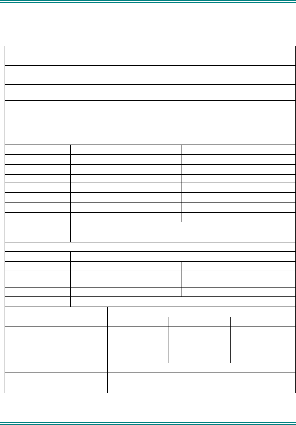
Table 1-1 Features for Control Variants
Feature: Model: 9022 9030
Control Controller
Microphone Control Unit with
Microphone
Display
8x14 char LCD
Graphics 102x64
pixels
8x14 char LCD
Graphics 102x64
pixels
Adjustable Display
Illumination
Yes Yes
Buttons and Keys Vol Up/Down
6 Function
12 Keypad
Send/End
Menu + Scroll
6 Function
12 Keypad
Send/End
Menu + Scroll
Speaker Yes Yes
Channel Spacing 12.5kHz/ 25kHz
Menu driven Yes Yes
Customisable Menus Yes Yes
SRM9000X8 800MHz SERVICE MANUAL
© TMC Radio 2008 page 3 TNM-M-E-0022 Issue 1
Table 1-2 Conventional-PMR Variants
Feature: Model: 9022 9030
Channels 1000 1000
Signalling CTCSS/DCS
Selcall CTCSS/DCS
Selcall
Attack Operation Yes Yes
DTMF Encode Yes Yes
PTT Limit Timer with
warning beeps
Yes Yes
Busy Channel Lockout Yes Yes
PTT Inhibit on Busy Yes Yes
Scanning 124 groups of up to 16 channels per group, 4 user defined
scan groups.
Voting Up to 200 groups consisting of up to 16 channels per
group.
Priority Scanning Yes Yes
Nuisance Delete Yes Yes
Phonebook 250 entries 250 entries
Multiax Yes Yes
Ignition Sense Input Yes Yes
VOX Handsfree Yes Option
600 Ohm Interface Option
SIB Option
ASIG Option
P25 Option

SRM9000X8 800MHz SERVICE MANUAL
© TMC Radio 2008 page 4 TNM-M-E-0022 Issue 1
Software Versions and Naming
There are various associated items of Software (SW) required for the SRM9000 radio and programmer to operate.
This section simply defines the naming rules of the SW files to allow identification and conformity. This allows
different versions of SW to be distributed and co-exist without confusion.
The SRM9000 Transceiver has three items of SW for digital and analog PMR, Trunking and Alignment.
The 9022 Controller Mic/Handsets has one SW file for its PIC and the 9030 Control Head has two SW files for its
Flash and EEPROM.
1.4.1 Filename Structure
Basically the Filename Structure is defined as follows:
• 2 character Application code
• 2 or 3 character SW Type code
• 3 character version number
• File Extension as required.
eg.
9etm533.bin
9ep_533.bin
9es_533.bin
9ecf101.hex
9ece101.hex
1.4.2 Application Code
This identifies the application the SW was initially designed for:
9e Standard SRM9000 Rev 9 Software
ae SRM9000 Rev 9 Software applicable for SRP9022
1.4.3 Software Type Code
This identifies different types of SW within an application.
s_ Startup
p_ Standard PMR. DMAP or No option board
p_s PMR with Scrambler/Discriminator option board
p_g PMR with Direct GPS
p_a PMR with ASI Map27option board
p_u PMR with ASI SUP option board
p_q PMR with ASI-G Map27option board
a__ 9022 Standard PMR. DMAP or No option board
a_s 9022 PMR with Scrambler/Discriminator option board
a_g 9022 PMR with Direct GPS
a_a 9022 PMR with ASI Map27option board
a_u 9022 PMR with ASI SUP option board

SRM9000X8 800MHz SERVICE MANUAL
© TMC Radio 2008 page 5 TNM-M-E-0022 Issue 1
a_q 9022 PMR with ASI-G Map27option board
bo Transceiver Boot-code
bc Transceiver Boot-Backup-code
bf Transceiver PLA-code
ba Transceiver PLA-Backup-code
Note. The above file names are not stored within the code. As a consequence, when the radio is read by the FPP,
the FPP will display version numbers and release dates for the Backup, Startup, PMR and DMAP codes. The
Bootloader, PLA Backup and PLA codes show release dates only.
SRM9000X8 800MHz SERVICE MANUAL
© TMC Radio 2008 page 6 TNM-M-E-0022 Issue 1
1.4.4 Version Number
This is a 3-digit number allocated by Engineering to identify the SW version.
e.g. 103 = Version 1.03
1.4.5 Exclusions
The Programmer SW does not follow the above rules as it is a PC based Program and its version number can be
easily identified by starting the SW. Later releases of SW will be backward compatible, unless deliberately not so,
in which case a different directory structure/path may be implemented.
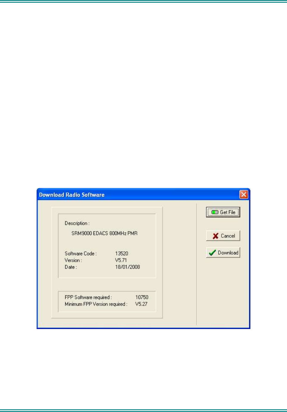
1.4.6 Displaying Software Versions
Each Transceiver SW code file (e.g. 9etm533.bin, etc.) contains version information about itself and possible
compatibility with Programming SW.
For Radio SW saved on Disk, this information can be displayed via the Programmer function:
Options : Upgrade_Software : Get_File
SRM9000X8 800MHz SERVICE MANUAL
© TMC Radio 2008 page 7 TNM-M-E-0022 Issue 1
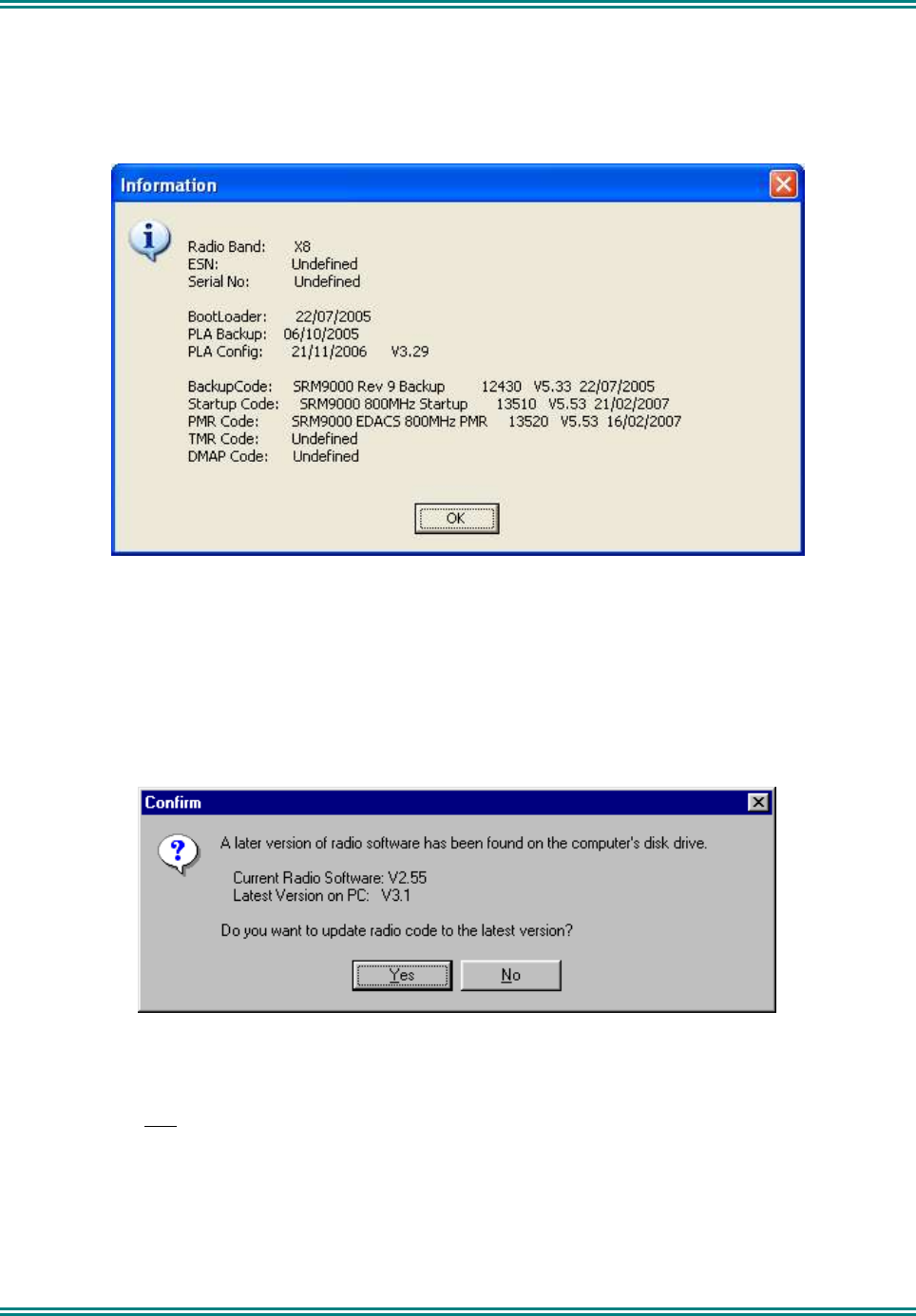
For Software loaded in the radio, information can be read from the Transceiver and displayed via the
Programmer function:
Options : Radio_Information
SRM9030 Control Head SW can be displayed on the Control Head by holding the ‘3’ button down when the radio
is switched on. SRM9022 Handset SW can be displayed by pressing the top side button when the radio is
switched on.
1.4.7 Automatic Version Upgrade Prompting
When a configuration is downloaded to the Transceiver, the Programmer performs a brief check on the SW
currently installed in the radio. If a later version of SW exists (on PC hard-disk) then the Programmer will prompt
the user with the following message:
NOTE. As early versions of FPP cannot recognise a more recent revision of the radio, it is important that the latest
FPP version is downloaded from http://www.tmcradio.com.
If YES is selected, the Transceiver Radio code is updated before the new configuration is downloaded.
If NO is selected, only the configuration is downloaded.
This process also updates the Startup code to ensure it is compatible with the loaded PMR code.
Note : If the …\SRM9000\FPP\RadioSW folder contains no files, then the above check will not be performed.

SRM9000X8 800MHz SERVICE MANUAL
© TMC Radio 2008 page 8 TNM-M-E-0022 Issue 1
1.4.8 Transceiver SW Description, Start-up and Backup-Software
The SRM9000 Transceiver software is split into the following separate modules:
• Bootloader and Backup Software
• Start-Up Software
• PLA and PLA-Backup Software
• Mainline PMR Software
When the Transceiver starts, it basically performs the following steps:
• Initial execution starts with the Bootloader code, which attempts to load the Start-Up Software (if Start-
Up checksum is bad, then the Backup Software is loaded.)
• Start-Up Software then downloads the PLA code (or PLA-Backup code if PLA checksum is bad) to the
PLA device. If both PLA and PLA-Backup checksums are bad then the radio is not operational and serial
communication is not possible.
• Start-Up Software then reads the On/Off switch plus Ignition-Sense lines and compares these with
saved parameters to determine if the radio should be continue to power-up or switch itself off again.
• Start-Up software then attempts to load PMR Mainline Software (dependent on saved parameter) and
switches execution to complete the power-up process and start normal operation.
If the Mainline Software cannot be loaded, or a Job file configuration has not been loaded (e.g. non-existent or
checksum fail) then execution switches to Backup Software until the error is corrected (e.g. by FPPing the radio).
There are three states that the radio can configure after switch-on:
• Mainline PMR Software (normal power-up)
If the radio does not have a valid Job file configuration loaded, then it will display a “No PMR Cfg”.
• Start-Up Software (characterised by “Alignment Mode” shown on the display). This is also the code that
is running when the radio is being aligned using the Alignment Tool.
• Backup Software (via various paths from above.)
1.4.9 Wailing Siren (Boot-up Software Corrupted)
A “WAILING SIREN” sound is emitted from the Loudspeaker while the radio is running in Boot Backup Software.
In this mode the FPP can be used to re-load a Jobfile, or re-load Start-Up or Mainline Operating Software.
Simply writing a Jobfile to the radio should allow the FPP to determine and update the offending software –
however there may be instances where the FPP cannot determine this and the Start-Up and Mainline Software
should be updated manually. This can be done using the FPP : Upgrade_Software : Get_File … then Download.
Both Start-Up Software (filename = 9es_xxx.bin) and Mainline PMR (9ep_xxx.bin) should be loaded if the FPP
cannot automatically fix the problem. The wailing siren should stop once the problem is fixed.
Note: Should these steps fail to restore the set and the Wailing Siren cease, the radio will need to be returned to
a Level 3 Service Centre for FLASH replacement.
1.5 ADJUSTMENT AND ALIGNMENT
There are no manual internal adjustments in the SRM9000. Re-programming and alignment is done using
software tools with the PCB installed in its chassis. For servicing, the radio PCB can be operated outside the
chassis provided that a temporary heatsink is fitted under the transmitter PA module for transmitter servicing and
that the receiver audio output be kept below 100mW for receiver servicing. Radio performance is only slightly
affected by operating without the outer sleeve but there will be some change to performance when the metal cans
are removed from the RF sections of the board.
On re-assembly, the PA module should be checked for a thin layer of heat-conducting paste. If this is missing or
dried-out, it should be replaced prior to re-assembly.

SRM9000X8 800MHz SERVICE MANUAL
© TMC Radio 2008 page 9 TNM-M-E-0022 Issue 1
1.6 CHASSIS ASSEMBLY
Important Note!
1.6.1 Torque Settings
Assembly of 'Chassis' (Inner Extrusion) to 'Outer Extrusion': 1.4 Nm (PA x 2), 1.25Nm (Others x 3)
Assembly of 'Front' and 'Rear' end-caps to 'Outer Extrusion': 1.4 Nm.
1.6.2 Thermal Compound Application
Just enough thermal compound should be applied to the PA tray to provide good thermal contact with the chassis.
Note. If thermal compound is old and difficult to spread, it should be discarded.
1.6.3 Assembly
The Inner extrusion should initially be nested together with the PCB and then the assembly slid into place within
the outer extrusion.
Positioning the inner extrusion upwards by hand, it is then important to insert all screws by hand and ensure they
have been fully inserted through the PCB, thereby locating the assembly correctly.
Whilst holding the inner extrusion upwards to ensure the assembly does not twist, lightly torque up the centre
screw of the row of three followed by the PA module mounting screw towards the middle of the chassis.
The remaining screws can then be screwed up to full torque followed by re-torque of the first two screws.
SRM9000X8 800MHz SERVICE MANUAL
© TMC Radio 2008 page 10 TNM-M-E-0022 Issue 1
1.7 SPECIFICATION
1.7.1 General
Operation
Single frequency simplex or two-frequency simplex (half-duplex).
Modulation
Frequency modulation (phase) F3E and F1E.
Operational Temperature Range
-30°C to +60°C
Storage Temperature Range
-40°C to +80°C
Supply Voltage Requirements
10.8V to 16.32V DC negative earth (13.8V nom.)
Current Consumption
Mobile With 9022 Control Mic Mobile With 9030 Alpha Head
Radio off ≤ 5mA ≤ 5mA
Standby (squelched): ≤ 200mA ≤ 210mA*
Rx Audio O/P:
300mW ≤ 450mA ≤ 500mA *
4.0W ≤ 1200mA ≤ 1250mA*
Transmit:
25W ≤ 7.0A
6W ≤ 3.0A
*Add 100mA to current consumption for the 9030 Control Head with backlight on.
Frequency Band Frequency Range
X8 Transmit Receiver
2 Frequency
Simplex 806-825MHz 851-870MHz
Turnaround 851-870MHz 851-870MHz
Channel Spacing 12.5kHz/ 25kHz
Frequency Stability (-30°C to 60°C) Less than ±1.5ppm
Dimensions (mm) Height Width Depth
Transceiver
9022 Controller Microphone
9030 Alpha Control Head
56
145*
300
170
68
120
165
30
130
* Does not include cable or strain relief
Weight
Transceiver
1.8kg
SRM9000X8 800MHz SERVICE MANUAL
© TMC Radio 2008 page 11 TNM-M-E-0022 Issue 1
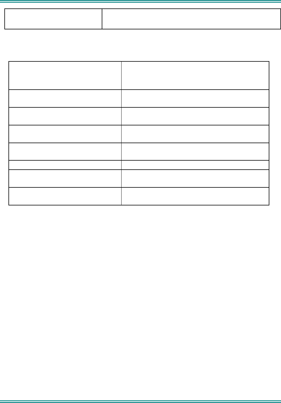
Regulatory Approvals FCC ID: STZSRM9000X8
IC: 7068A-M9000X8
1.7.2 Transmitter
Power Output
Any two levels are programmable:
High Power: 25W Adjustable down to 1W
Low Power: 1W Adjustable up to 25W
Carrier Attack Time
Less than 50 ms
Duty Cycle
1 minute transmit: 4 minutes receive
Spurious Emissions
< -20dBm
FM Hum & Noise
25kHz Channel Spacing: >40dB
Audio Frequency Distortion < 5%.
Audio Frequency Response
300 to 3000Hz +1dB to -3dB of a 6dB/octave pre-
emphasis curve.
Audio Sensitivity (1kHz)
(User programmable via FPP)
RJ8 Connector: 40mV±2dB from 470Ω source impedance.
Option Audio: 40mV±2dB.

SRM9000X8 800MHz SERVICE MANUAL
© TMC Radio 2008 page 12 TNM-M-E-0022 Issue 1
1.7.3 Receiver
Sensitivity
Analog
C4FM
< -117.5dBm for 12dB SINAD
< -116dBm for 5% BER
Adjacent Channel Rejection
Analog 25kHz
C4FM
>70dB
>60dB
Offset Channel Rejection (NPSPAC) >20dB
Intermodulation Rejection >70dB
Spurious Response Rejection >70dB
Blocking >90dB
Conducted Spurious Emissions <-57dBm
FM Hum & Noise (Analog 25kHz) >40dB
Mute Range
Typically 6dB to 25dB SINAD
Typical preset level 10dB ±2dB SINAD
Receiver Attack Time <150mS
Receiver Closing Time <90mS
Audio Distortion 4W into 4Ω at <5% distortion
Audio Frequency Response 300 to 3000Hz: +2dB to -8dB of a 6dB/octave de-emphasis
curve
Deviation Sensitivity
(for rated audio at 1kHz) 20% to 40% PSD
SRM9000X8 800MHz SERVICE MANUAL
© TMC Radio 2008 page 13 TNM-M-E-0022 Issue 1
1.7.4 Signalling
1.7.4.1 CTCSS
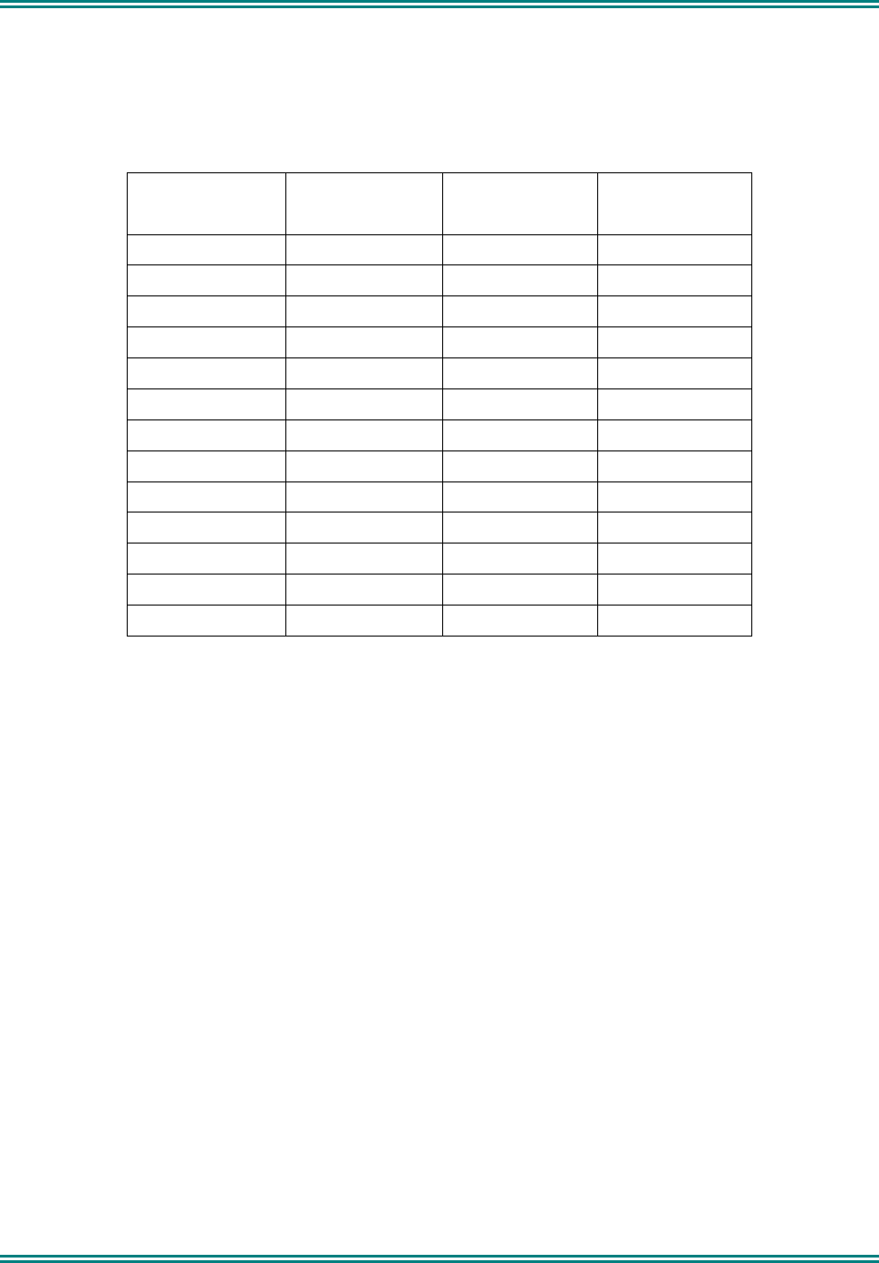
38 standard CTCSS Tones and 13 non-standard tones are supported as per the table below:
Standard
Frequencies
Standard
Frequencies
Standard
Frequencies
Non-Standard
Frequencies
67.0 107.2 167.9 69.3
71.9 110.9 173.8 150.0
74.4 114.8 179.9 159.8
77.0 118.8 186.2 165.5
79.7 123.0 192.8 171.3
82.5 127.3 203.5 177.3
85.4 131.8 210.7 183.5
88.5 136.5 218.1 189.9
91.5 141.3 225.7 196.6
94.8 146.2 233.6 199.5
97.4 151.4 241.8 206.5
100 156.7 250.3 229.1
103.5 162.2 254.1
CTCSS Encoder
Tone Deviation:
25kHz channel spacing: 500 to 750Hz
NPSPAC: 400 to 600Hz
Tone Distortion: Less than 5.0%
Tone Frequency Error: Less than ±0.3%

SRM9000X8 800MHz SERVICE MANUAL
© TMC Radio 2008 page 14 TNM-M-E-0022 Issue 1
CTCSS Decoder
Bandwidth Complies with TIA-603 part 3.4.6
Deviation Sensitivity Less than 6.0% of system deviation (for decode with full RF quieting)
Noise Immunity Less than 500ms dropout per minute at 10dB SINAD
(CTCSS tone deviation 10% of system deviation. RF deviation 60% at 1000Hz).
False Decode Rate Less than 1 false decode per 30 minutes (no carrier input).
Blocking For no dropouts in one minute, interfering tone at 90% of system deviation
(CTCSS tone at 10% of system deviation) as follows:
Full quieting signal: 310Hz to 3000Hz
20dB SINAD RF signal: 320Hz to 3000Hz
12dB SINAD RF signal: 350Hz to 3000Hz
Attack Time Less than 250ms (tone frequency >100Hz)
Less than 350ms (tone frequency <100Hz)
Closing Time Less than 250ms
Squelch Tail Elimination Less than 50ms
1.7.4.2 Selcall
The following tone sets are supported as per tables below:
• ST-500: CCIR, EEA, ZVEI, DZVEI, EIA
• ST500/CML: ZVEI_3, DZVEI
• CML: CCIR, EEA, ZVEI
• SIGTEC: CCIR, CCIRH, EEA, ZVEI_1, XVEI_2, ZVEI_3, NATEL, EIA
• SEPAC: CCIR, EEA, ZVEI_1, ZVEI_2, ZVEI_3, EIA

SRM9000X8 800MHz SERVICE MANUAL
© TMC Radio 2008 page 15 TNM-M-E-0022 Issue 1
Selcall Tone Frequency Table
Tone CML ST500 SIGTEC SIGTEC SEPAC CML ST500 SIGTEC
CCIR CCIR CCIR CCIRH CCIR EEA EEA EEA
0 1981 1981 1981 1981 1981 1981 1981 1981
1 1124 1124 1124 1124 1124 1124 1124 1124
2 1197 1197 1197 1197 1197 1197 1197 1197
3 1275 1275 1275 1275 1275 1275 1275 1275
4 1358 1358 1358 1358 1358 1358 1358 1358
5 1446 1446 1446 1446 1446 1446 1446 1446
6 1540 1540 1540 1540 1540 1540 1540 1540
7 1640 1640 1640 1640 1640 1640 1640 1640
8 1747 1747 1747 1747 1747 1747 1747 1747
9 1860 1860 1860 1860 1860 1860 1860 1860
A 2400 1055 2110 2400 2400 1055 1055 2110
B 930 .... 2400 930 1055 930 .... 1055
C 2247 2400 1055 2247 2247 2247 2400 2400
D 991 .... 2247 991 991 991 .... 2247
E 2110 2110 930 2110 2110 2110 2110 930
F .... .... 991 1055 .... .... .... 991
Tone SEPAC CML ST500 SIGTEC SEPAC SIGTEC SEPAC SIGTEC
EEA ZVEI ZVEI ZVEI-1 ZVEI-1 ZVEI-2 ZVEI-2 ZVEI-3
0 1981 2400 2400 2400 2400 2400 2400 2200
1 1124 1060 1060 1060 1060 1060 1060 970
2 1197 1160 1160 1160 1160 1160 1160 1060
3 1275 1270 1270 1270 1270 1270 1270 1160
4 1358 1400 1400 1400 1400 1400 1400 1270
5 1446 1530 1446 1446 1446 1446 1446 1400
6 1540 1670 1670 1670 1670 1670 1670 1530
7 1640 1830 1830 1830 1830 1830 1830 1670
8 1747 2000 2000 2000 2000 2000 2000 1830
9 1860 2200 2200 2200 2200 2200 2200 2000
A 1055 2800 970 2600 2800 970 885 2400
B 970 810 .... 2800 970 885 741 885
C 2247 970 2800 741 885 741 2600 741
D 2400 886 .... 970 .... 2600 .... 2600
E 2110 2600 2600 810 2600 2800 970 2800
F .... .... .... 886 .... 600 .... 600
SRM9000X8 800MHz SERVICE MANUAL
© TMC Radio 2008 page 16 TNM-M-E-0022 Issue 1
Tone SEPAC ST500/CML ST500 SIGTEC SIGTEC SEPAC ST500
ZVEI-3 ZVEI-3 DZVEI DZVEI NATEL EIA EIA EIA
0 2200 2400 2200 2200 1633 600 600 600
1 970 1060 970 970 631 741 741 741
2 1060 1160 1060 1060 697 882 882 882
3 1160 1270 1160 1160 770 1023 1023 1023
4 1270 1400 1270 1270 852 1164 1164 1164
5 1400 1530 1400 1400 941 1305 1305 1305
6 1530 1670 1530 1530 1040 1446 1446 1446
7 1670 1830 1670 1670 1209 1587 1587 1587
8 1830 2000 1830 1830 1336 1728 1728 1728
9 2000 2200 2000 2000 1477 1869 1869 1869
A 885 885 2600 825 1805 459 2151 2151
B 741 .... .... .... 1995 2151 1091 ....
C 2600 810 886 2600 1300 2600 2400 2010
D .... .... 810 .... 1700 2010 .... ....
E 2400 970 2400 2400 2175 2433 459 459
F .... .... .... .... 2937 2292 .... ....
Selcall Tone Periods
4 preset lengths selectable: 20ms to 4 seconds in 1ms increments.
1.7.4.3 DTMF
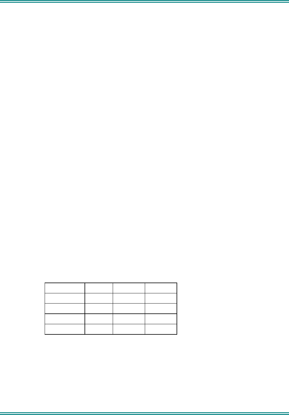
DTMF Encode supported via keypad:
TONES 1209Hz 1336Hz 1477Hz
697Hz 1 2 3
770Hz 4 5 6
852Hz 7 8 9
941Hz * 0 #
Tone Period, programmable: 0 – 2.55s in 10ms steps.
Inter-Tone Period, programmable: 0 – 2.55s in 10ms steps.
Link Establishment Time, programmable: 0 - 10s in 10ms steps.
Tx Hang Time, programmable: 0 – 9.99s in 10ms steps.
Side-Tone in Loudspeaker: selectable via programmer
SRM9000X8 800MHz SERVICE MANUAL
© TMC Radio 2008 page 17 TNM-M-E-0022 Issue 1
1.7.4.4 DCS
Data rate 134 bits per second, frequency modulated
7.46ms/bit
171.6ms per codeword continuously repeating
Deviation 500 to 1000Hz for 25kHz channel spacing
400 to 800Hz (NPSPAC)
Codeword size 23 bits comprising:
8 bits - DCS code (3 octal digits 000-777)
3 bits - Fixed octal code 4
11 bits - CRC (error detection) code
Available Codes 104 codes from 512 theoretically possible codes – see below
Turn off code 200ms 134Hz tone at PTT release
DCS Codes can be Transmitted “Normal” or “Inverted” (programmable).
The radio can receive DCS codes in either Transmitted “Normal” or “Inverted” or both (selectable via programmer).
Valid DCS Codes
023 132 255 413 612
025 134 261 423 624
026 143 263 431 627
031 145 265 432 631
032 152 266 445 632
036 155 271 446 654
043 156 274 452 662
047 162 306 454 664
051 165 311 455 703
053 172 315 462 712
054 174 325 464 723
065 205 331 465 731
071 212 332 466 732
072 223 343 503 734
073 225 346 506 743
074 226 351 516 754
114 243 356 523
115 244 364 526
116 245 365 532
122 246 371 546
125 251 411 565
131 252 412 606
1.7.4.5 C4FM
Digital speech format in accordance with TIA/EIA 102 requirements.
SRM9000X8 800MHz SERVICE MANUAL
© TMC Radio 2008 page 18 TNM-M-E-0022 Issue 1
1.7.5 Environmental
Note: Operation of the equipment is possible beyond the limits stated but is not guaranteed.
Operational Temperature
-30°C to +60°C MIL-STD-810F Methods 501.4 and 502.4, Proc II
Storage Temperature
-40°C to +80°C MIL-STD-810F Methods 501.4 and 502.4 Proc I
Vibration Stability
MIL-STD-810F Method 514.5C-1, Proc I, Cat 4 and USFS Vibration Standard
Cold
MIL-STD-810F Method 502.4, Proc II
High Temperature
MIL-STD-810F Method 501.4, Proc II
Humidity
MIL-STD-810F Method 507.4-1
Low Pressure
Storage MIL-STD-810F Method 500.4, Proc I
Operational MIL-STD-810F Method 500.4, Proc II
Sand and Dust
MIL-STD-810F Method 510.4, Procedures I and II
Shock
MIL-STD-810F Method 516.5, Proc I
Product Sealing
MIL-STD-810F Method 505.4, Proc III
(Equivalent to IEC529 rating IP54)

SRM9000X8 800MHz SERVICE MANUAL
© TMC Radio 2008 page 19 TNM-M-E-0022 Issue 1
2. SERVICE PHILOSOPHY
2.1 SERVICE CONCEPT
The SRM9000 series has been designed to provide low cost analog and digital speech mobile transceivers, using
common core electronics, software and interfacing. It is a requirement that once the customer has purchased
equipment, TMC Radio can follow this by providing an ongoing, high level of customer support together with a
competitive and professional servicing activity.
There are three levels of service available:
Level Activity Recommended Spares Recommended Test
Equipment
1 Replacement of complete
transceiver/antenna/fuses
Reprogramming
Antennas, Fuses
Ancillaries Multimeter P.C.
Radio software
Programmer
2 Replacement of PCB or
mechanical component
replacement, Cosmetic repair
Listed in Level 2 Spares
Schedule As above + service aids and
test equipment
3 Repair by PCB or mechanical
component replacement,
Cosmetic repair.
Repair of Radio PCB to
component level in CRU.
Listed in Level 2 Spares
Schedule
Radio PCB components
only available to CRU.
As above + service aids and
test equipment
2.2 WARRANTY
Initially, the normal 12-month warranty will apply to all radios and ancillaries.
2.2.1 Service Within and Out Of Warranty
The field Service Level for the SRM9000 mobile is LEVEL 2, PCB replacement.
LEVEL 2 Service, PCB (only) and case part replacement, will be carried out in field repair workshops, or the
Central Repair Unit (CRU) if required.
LEVEL 3 Service (Radio PCB component level repair) will ONLY be carried out in the Central Repair Unit. For
this, the complete radio must be returned to the CRU.
A PCB replacement program may be offered by the CRU in some countries.
2.3 SOFTWARE POLICY
Software provided by TMC Radio shall remain the Company's property, or that of its licensors, and the customer
recognises the confidential nature of the rights owned by the Company.
The customer is granted a personal, non-exclusive, non-transferable limited right of use of such software in
machine-readable form in direct connection with the equipment for which it was supplied only.
In certain circumstances the customer may be required to enter into a separate licence agreement and pay a
licence fee, which will be negotiated at the time of the contract.

SRM9000X8 800MHz SERVICE MANUAL
© TMC Radio 2008 page 20 TNM-M-E-0022 Issue 1
The customer undertakes not to disclose any part of the software to third parties without the Company's written
consent, nor to copy or modify any software. The Company may, at its discretion, carry out minor modifications to
software. Major modifications may be undertaken under a separate agreement, and will be charged separately.
All software is covered by a warranty of 3 months from delivery, and within this warranty period the Company will
correct errors or defects, or at its option, arrange free-of-charge replacement against return of defective material.
Other than in the clause above, the Company makes no representations or warranties, expressed or implied such,
by way of example, but not of limitation regarding merchantable quality or fitness for any particular purpose, or that
the software is error free, the Company does not accept liability with respect to any claims for loss of profits or of
contracts, or of any other loss of any kind whatsoever on account of use of software and copies thereof.

SRM9000X8 800MHz SERVICE MANUAL
© TMC Radio 2008 page 21 TNM-M-E-0022 Issue 1
3. TECHNICAL DESCRIPTION
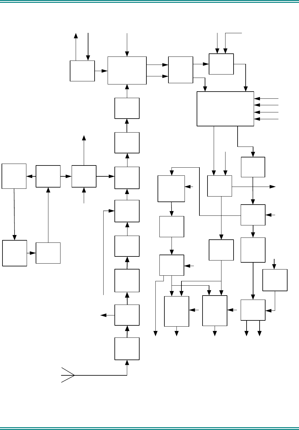
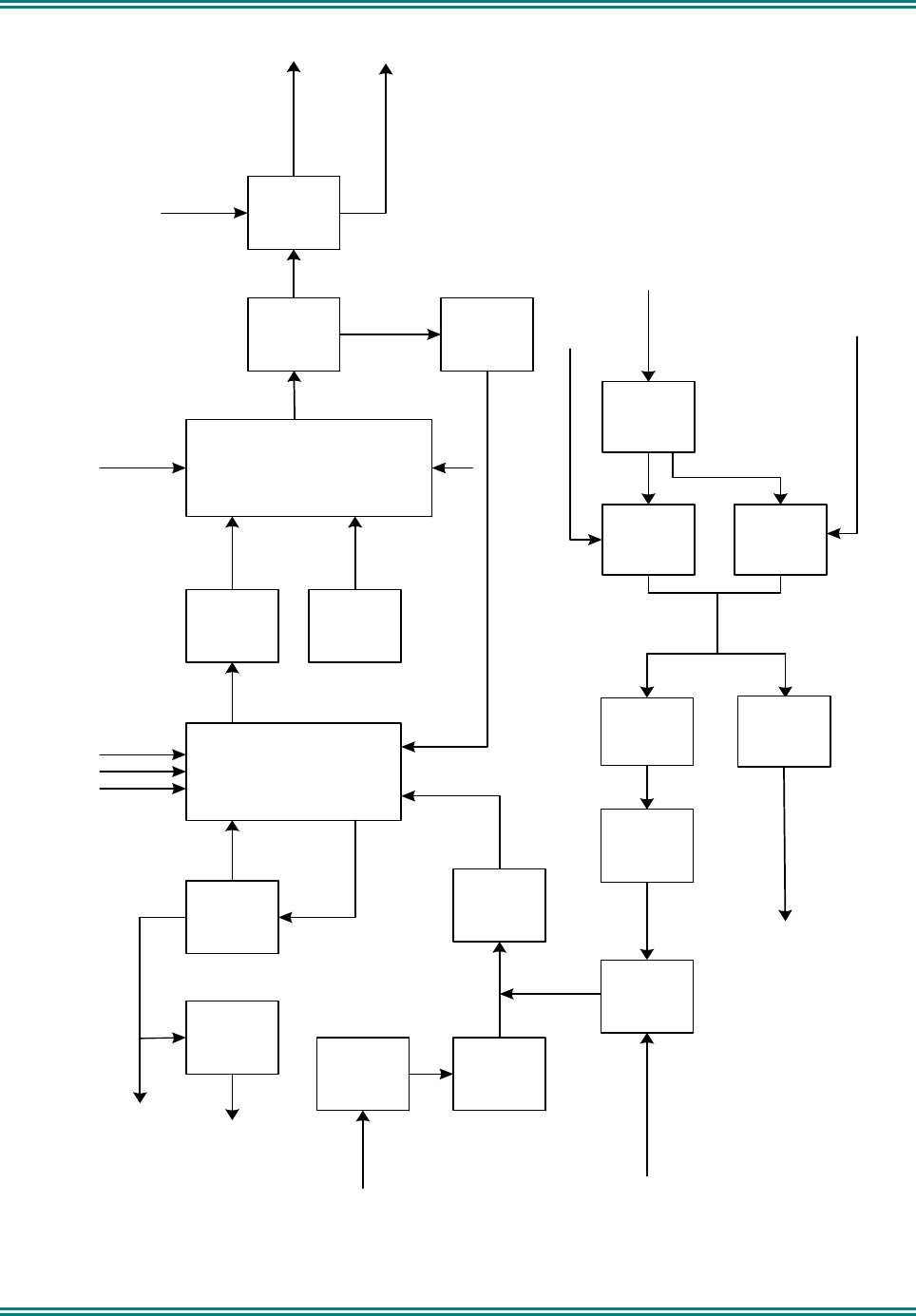
3.1 RECEIVER
Refer to Figure 3-1.
3.1.1 Front End Filters and RF Amplifier
The receiver input signal from the antenna passes through the harmonic filter and antenna T/R switch. With the
mobile in receive mode, diodes D580, D582 and D583 in the antenna switch are reverse biased allowing the
receiver input signal to be coupled through to the receiver front-end with minimal loss. The overall insertion loss of
the harmonic filter and switch is approximately 0.8dB.
The signal is then fed through SAW bandpass filter (Z400) to the input of the RF amplifier (Q404). The SAW filter
bandpass covers 851MHz to 870MHz. The RF amplifier stage comprises a low noise transistor amplifier (Q404)
that is compensated to maintain good linearity and low noise matching; this provides excellent intermodulation and
blocking performance across the full operating range. The overall gain of the front-end is approximately 9dB.The
RF amplifier has constant current bias controlled by Q402. The output of the RF amplifier is coupled through a
varactor-tuned bandpass filter comprising of two ceramic resonators (Z430 and Z431). The varactors have
individual PWM tuning voltages, TUNE 1 and TUNE 2, that are derived from PLA (U300). The tuning voltages
values for the filter varactors are controlled by the alignment data stored in the radio. The DSP processes these
data to optimise the filter tuning for each of the programmed channel frequencies.
A negative bias supply originates from the DSP/PLA as a PWM signal for the two filter tuning voltages for the
specific channel frequency selected. The PWM signal, which is dependent on channel frequency and tuning,
passes through level shifting transistors Q451 to Q454, where it is converted to a negative voltage in the range
-0.5V to -11.5V. The -12.0V rail for the level translators is generated by U904E/F, with D903 to D906 providing the
required voltage multiplication.
3.1.2 First Mixer and IF Section
The output of the ceramic resonator pair is then fed into U441, a high performance passive mixer that converts the
RF signal to a IF of 45MHz. The first local oscillator injection level is typically +8dBm with high side injection.
Following the mixer is a IF amplifier (Q461) that provides approximately 15dB of gain and, in association with its
output circuitry, presents the required load conditions to the 4 pole 45MHz crystal filters Z471A/Z471B.
The crystal filters provide part the total required selectivity for adjacent channel operation with the remaining
selectivity provided by a DSP bandpass filter algorithm.
3.1.3 Quadrature Demodulator
Additional IF gain of approximately 44dB occurs in U481, which is a dedicated IF AGC Amplifier and Quadrature
Demodulator. The AGC voltage for U481 is derived from the RSSI function of the DSP. The onset of AGC
operation occurs when RF input signal level at the antenna connector exceeds -90dBm and can reduce the gain
by approximately 100dB for strong signals.
Conversion of the 45MHz IF signal to I and Q baseband signals is carried out by the demodulator section of U481.
The 90MHz second local oscillator signal for U481 is generated by VCO Q730, which is phase locked by the PLL
CPIF output of U721, via feedback signal FINIF.
SRM9000X8 800MHz SERVICE MANUAL
© TMC Radio 2008 page 22 TNM-M-E-0022 Issue 1
Antenna
Switch
D581/
582/D583
Bandpass
Filter
Z400
RF Amp
Q404
Bandpass
Filter
Mixer
U441
IF Amp
Q461
4-Pole
45 MHz
Filters
Z471A/B
Antenna
Filter
L592,L593
& L594
IQ
Demodulator
U481
TX/RX
Switch
D641/
D642
RX VCO
Q623
VCO
Buffer
Q631/
Q632
Synthesiser
Buffer
Q640
90 MHz
VCO
Q730
RX/TX
AF
Switch
U801C
CODEC
U800
Tx/Disc
AF
Switch
U801B
Speaker
Switch
Q810/
811/Q813
Speaker
Amp
U805
AF Amp
U803B
VCO Control Volts
To TX Mixer FINIF
to U721
QI
From PLA/DSP
TX Mod Out
To TX VCO
SPKR_ON
SPKR_OUT 1
SPKR_OUT 2
From PLA TUNE_1 & 2
To TX PA
Tx Audio
from
PLA
U300
from U721
CPIF
Aux Gain
Switch
U806A
AF Amp
U803A
Rx Audio
Mode 2
U302C
Rx Audio
Mode1
U806C
GAIN
De-
emphasis
Network
Rx Audio
Gate
U302B
Rx Audio
Mode3
U806B
AUDIO_OUT 3
(Option Audio)
AUDIO_OUT 1
(Option Audio)
AUDIO_OUT 2
( H/S Audio)
EN 1
EN 2
.
.
EN 3
Q
I
Synthesiser
U721
RX_PSU
EN 4
AF Amp
U802A
CPP
TX_MOD
AGC
TX_MODEfrom
PLA
U300
DATA_EN
Differential
Amp
U491
Figure 3-1 Receiver Block Diagram

SRM9000X8 800MHz SERVICE MANUAL
© TMC Radio 2008 page 23 TNM-M-E-0022 Issue 1
3.1.4 Receiver Audio Processing
The baseband audio from the IQ Demodulator is applied to a differential amplifier (U941A/ U941B) that converts
the balanced demodulator I and Q output signals to unbalanced inputs for the CODEC (U800).
All receiver audio processing and filtering functions are performed by the CODEC under the control of the DSP.
The receiver I and Q analog baseband signals are converted to digital signals by the CODEC ADC before being
applied to a series of digital filters that provide the final stages of adjacent channel filtering, high pass and low pass
audio filtering, mute noise processing, and volume control level for narrow and wideband operation. The fully
processed signal is then converted to an analog audio signal by the CODEC DAC and then applied to conventional
audio amplifiers (U803A/B) and the loudspeaker amplifier (U805).
In addition, Discriminator Audio is derived from the second CODEC output channel and then amplified by U802A
after which it is applied to one of the radio I/O connectors for option purposes. Discriminator Audio is a preset level
set by the FPP and is independent of squelch operation.
There are two speaker options available, a half-bridged configuration using a speaker across balanced output
SPKR OUT1 and 2, which provides an audio output level of up to 4 watts into 4 ohms. The other option is a full
bridge configuration using a high power speaker across SPKR OUT1 and 2 and providing an audio output level of
up to 10 watts into 8 ohms; this high power option is enabled by adding 0 ohm resistor, R859. The carrier and
signalling mute functions are performed by Q810/Q811/Q813 under DSP control. De-emphasis to the audio PA
(U805) is performed by R861 and capacitor C872. Flat audio is provided to connector S1-6 via amplifier U803A.
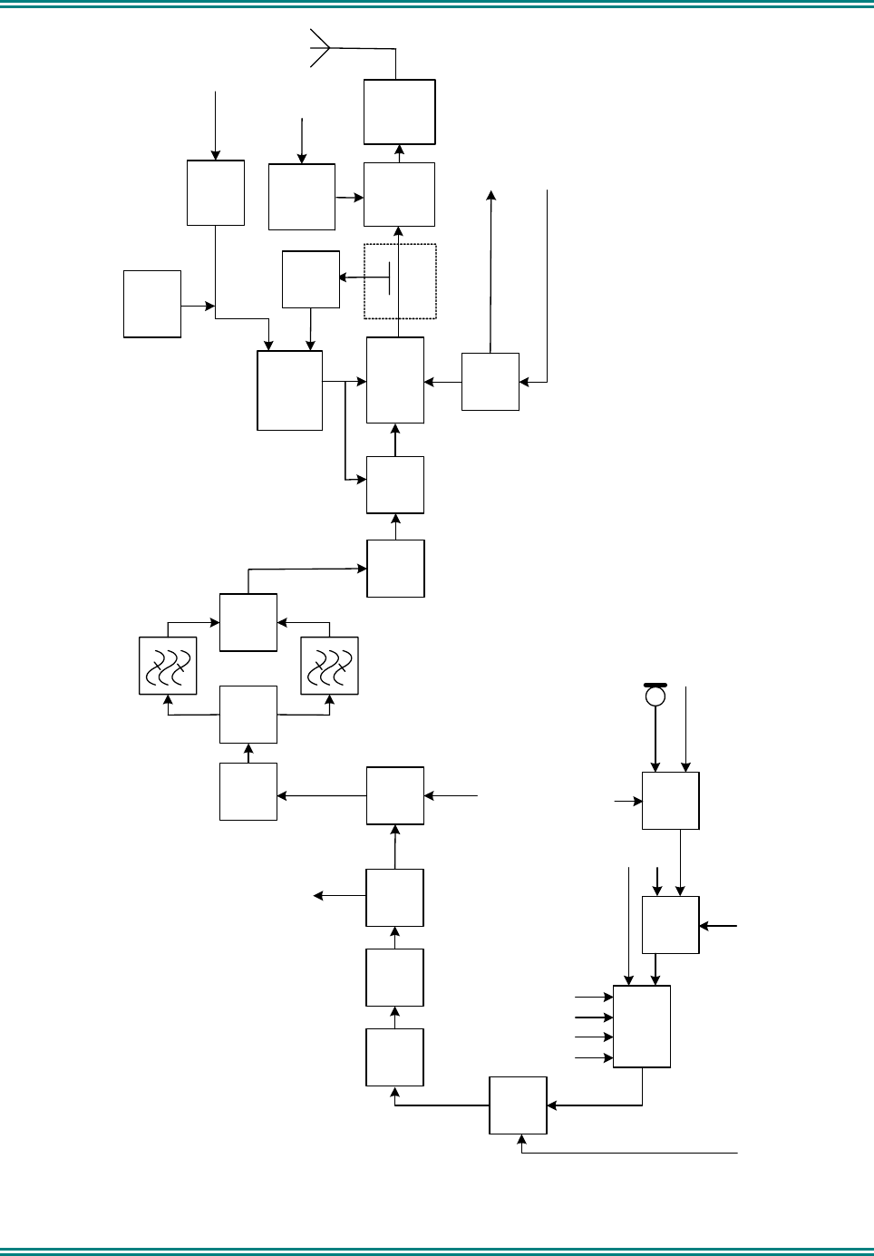
3.2 TRANSMITTER
Refer to Figure 3-2.
3.2.1 Drivers and PA Stages
The carrier frequency for the transmitter is generated by combining the receiver first LO with the receiver second
LO in TX mixer (U650).
The output of the mixer (U650) is fed into a broadband amplifier (U670) via a tuned filter comprising of varactors
D660 and D661, to reduce the unwanted mixer products. The tuning voltage for the filter varactors, TUNE 1N, is
derived from level translators Q451 and Q452. U670 amplifies signals from 806MHz to 825MHz for two frequency
simplex applications and 851MHz to 870MHz for turnaround operation. The output of U670 connects to a diode
switch arrangement consisting of D681 to D684; this switch is used to select pairs of SAW filters on either the 806
to 825MHz band with Z681 and Z683, or the 851 to 870MHz band with Z682 and Z684. The diode switch is
controlled by transistors Q681 and Q682.
The carrier signal level at the output of the SAW filters is approximately –7dBm. This signal is then further
amplified in subsequent broadband stages Q691 to approximately +2dBm, Q501 to +15dBm, Q521 to +17dBm
and Q531a to +20dBm. Each of these stages has a resistive attenuator network to provide isolation from the
affects of transient load impedance changes. The output of final driver (Q531a) is fed through a resistive network
consisting of R536, R537 and R538, to the input of the broadband power amplifier module (U561) at a level of
approximately +16dBm.
The PA module (U561) contains three MOSFET stages to achieve the required maximum RF output power level of
+44.4dBm (27.5 watts).
Note: Care should be taken during servicing, since if for any reason the drive power is lost while the power control
voltage is high, the current into the PA may exceed its specification. Therefore the power supply current limit
should be monitored at all times and preset to as low as required. The radio has some additional inbuilt
safeguards, but these should not be relied on.
Final power output settings are derived from alignment data stored in flash memory during the initial factory
alignment. The DSP processes these data to optimise the power output level relative to the selected programmed
channel frequencies.
PA current is monitored via comparator U551B, the output of which is passed via a temperature compensation
network R552, R553 and NTC R554, to the ADC, U301C. U301C samples the applied voltage and then passes it
to the PLA, after which it is processed by the DSP. The PA current limit value is calibrated as part of the alignment
procedure.

SRM9000X8 800MHz SERVICE MANUAL
© TMC Radio 2008 page 24 TNM-M-E-0022 Issue 1
3.2.2 Power Control
The final output power is stabilised by a power control feedback loop. A printed circuit transmission line, L561,
resistor R560, diodes D561A and D561B, and other associated components, form the power detector. Comparator
U551A and associated components provide the power setting and power control functions. Forward and reverse
power is sampled by the power detector and applied as a DC voltage to the inverting input of the comparator. The
TX_PWR set voltage is a DC voltage proportional to the programmed Tx power setting and is applied to the non-
inverting input of the comparator.
The TX_PWR calibration voltage originates from the PLA as a PWM signal and is integrated for application to the
comparator.
The PA module output level variation due to variations of supply voltage, output load or temperature, is detected
and applied to the comparator. The comparator proportionally adjusts the PA module bias supply and the bias
supply for the PA driver (Q531A) and thus the PA drive level. High temperature protection is provided by thermistor
R557, that progressively reduces the power level if the PA module temperature becomes excessive.
3.2.3 Antenna Changeover and Harmonic Filter
The antenna changeover circuit consisting of pin diodes D581, D582 and D583, is switched by transistors Q571,
Q572 and Q573 and associated circuitry, allowing the transmitter output to be coupled to the antenna while
providing isolation for the receiver input. With the transmitter switched on, the diodes are forward biased allowing
power to be coupled through to the antenna and isolating the receiver by grounding its input at C585. The short
circuit at the receiver input is transformed to an effective open circuit at D581, by a lumped transmission line
(L591), which minimises transmitter loading. With the transmitter switched off, the diodes are reverse biased
allowing the receiver input signal to reach the receiver front end with minimal loss. The harmonic reject, low pass
filter comprises L592, L593, L594 and associated capacitors.
3.2.4 Transmitter Audio Processing
The microphone audio input signal is applied to the radio microphone input (AUDIO_IN1) and is derived from an
external microphone and pre-amplifier that provides a typical speech signal level of 40mV RMS. U801A is a control
gate that switches between AUDIO_IN1 and OPTION_AUDIO1 to provide external audio options and data input.
U801C provides CODEC input switching which selects either the receiver “I” signal or transmitter audio/data
signals depending on the Tx/Rx mode. All pre-emphasis, filtering, compression and limiting processes for narrow
and wideband operation, are carried out in the DSP after A-D conversion by CODEC (U800). The processed
transmitter audio/data from the CODEC output at VOUTR, is applied to the VCO as a modulation signal with a
level of approximately 200mV P/P via AF Switch (U801B).
SRM9000X8 800MHz SERVICE MANUAL
© TMC Radio 2008 page 25 TNM-M-E-0022 Issue 1
Directional
Coupler
RX VCO
Q623
VCO
Buffer
Q631/
Q632
TX/RX
Switch
D641/
Q642
TX
Driver
Q531a TX PA U561
Antenna
Switch
D581/
D582/
D583
Power
Control
Comparator
U551A
Antenna
Filter
L592/
L593/L594
To RX
Mixer
LO1_RX
ADC/DAC/
CODEC U800
TX_MOD
From PLA/DSP
RX/TX
AF
Switch
U801C
Q
I
Switch
U801A
Standard
Microphone
External Accessory
Audio
Current
Sense
U551B
TX Current Sense to
PLA
13V8_UNSW
Audio
Gate
U801B
DATA_EN
TX
Buffer
Amp
Q521
TX/RX AF Control
From PLA
TX_MODE
Internal MIC/ External
Audio Control From
PLA
MOD_SW
CURRENT_SENSE
Antenna
Switch
Control
Q571/572
Power
Control
Detector
D561
Integrator
R308/
C307
PWM TX
Power Set
from PLA
PA_ON from
PLA
Thermal
Shut Back
R557
TX_PWR
Switch
D683/
D684
Switch
D681/
D682
TX
Buffer
Amp
Q670
TX Mixer
806 - 825 MHz
851 - 870 MHz
TX_LO2
RX_LO
Figure 3-2 Transmitter Block Diagram

SRM9000X8 800MHz SERVICE MANUAL
© TMC Radio 2008 page 26 TNM-M-E-0022 Issue 1
3.3 FREQUENCY SYNTHESISER
3.3.1 General
Refer to Figure 3-3.
The frequency synthesiser consists of the RX VCO, the second local oscillator VCO (90MHz), loop filters, varactor
positive bias generator, reference oscillator, external divider and an integrated fractional N phase locked loop IC
(U721).
3.3.2 PLL
The PLL is a high performance delta-sigma fractional-N device with an auxiliary integer-N PLL (U721).
The PLL contains two prescalers, programmable dividers and phase comparators, to provide a main and an
auxiliary PLL. The main PLL of U721 controls the frequency of the RX VCO via CPRF at pin 1 and VCO feedback
to FINRF at pin 4. The auxiliary PLL is used to control the receiver 90MHz second LO VCO via CPIF at pin 16 and
VCO feedback to FINIF at pin 13. The PLL operation involves the external frequency divider (U760) dividing the
15.36MHz reference oscillator by 32 to produce a PLL input reference of 480kHz; this reference is used directly by
the RF PLL phase detector. The RX VCO frequency is sampled and divided down and compared to the reference
frequency. Any error produces an offset to the control voltage output that is used to correct the VCO frequency. A
valid lock detect output is derived from LD pin 12 and is sampled by the PLA. During transmit, if an unlocked signal
is detected, the radio will switch back to receive mode. An unlocked signal in receive mode will cause the radio to
beep.
For the IF PLL, the input reference is divided by 4 to produce a 120kHz phase comparator reference, which is a
sub-multiple of the 90MHz second LO VCO.
3.3.3 VCOs
The main RX VCO uses a low noise bipolar transistor (Q623) and associated parts to generate signal frequencies
from 896MHz to 960MHz. Electronic tuning is provided by varactor diode (D610) with its control voltage derived
from the Loop Filter, PLL and +16 volt Bias Generator. VCO buffer (Q631 and Q632) isolates the VCO from any
load variations from its following circuits. The active power supply filter (Q622) minimises any supply related noise.
A PLL feedback signal is returned from the VCO buffer output via amplifier Q640.
The 90MHz receiver second LO VCO comprises Q730 and associated parts. Automatic tuning is achieved by
applying a control voltage to D730 and D731, via Loop Filter R718, R719, R720, C732, C733 and C734.
3.3.4 Positive Bias Generator and Loop Filter
A positive bias voltage for varactor D610, has been used to achieve the required broadband tuning range of the
VCO. PLL device, U721, is programmed to deliver a nominal +1.65V output from phase detector/charge pump
CPRF, for any channel frequency selected. The CPRF voltage is filtered by the Loop Filter comprising C605,
C607, C607a, C609a, R609 and R612; the loop filter removes any synthesiser noise or reference products. The
resulting low noise control voltage is applied to the anode side of VCO varactor. The cathode voltage of D610 is
controlled by the output of voltage level translator Q780, Q781, Q782 and Q783. The level translator supply
voltage is +16V, which is provided by U904E/F. The level translator output voltage is accurately controlled by the
PLA/DSP from values stored during VCO alignment. This voltage is varied versus frequency to maintain a typical
CPRF value of +1.65V.
3.3.5 Phase Modulator
The modulation path for audio, data and higher frequency CTCSS signals is via varactor D610 and associated
components. The reference input to the PLL (REFIN) provides the low frequency modulation path via a phase
modulator.
The phase modulator comprises the following sections:
- Integrator U761A is a low pass filter providing 6dB per octave attenuation to frequencies above approximately
10Hz.
- Divider U760 divides the 15.36MHz reference frequency down to 480kHz.
- Ramp generator Q771 and Q772 provides a sawtooth output, the slope of which is adjustable
via the MOD_BAL line. This adjustment is set via a DAC output controlled from the Alignment Tool.
Adjustment of the ramp slope effectively changes the Phase Modulator gain by modification of the
Schmitt Trigger switching points after modulation from the Integrator is combined to the sawtooth ramp.

SRM9000X8 800MHz SERVICE MANUAL
© TMC Radio 2008 page 27 TNM-M-E-0022 Issue 1
The divided reference signal is differentiated and discharges C778 via Q771, after which Q771 is turned off
allowing C778 to recharge via constant current source Q772.
The Schmitt Trigger comprising Q774, Q775 and Q776, converts the modulation combined with the sawtooth
ramp, to a square wave output, the duty cycle of which is controlled by the ramp slope and modulation.
The Modulation Balance adjustment is carried out using a CODEC-generated 100Hz square wave applied to
the TX_MOD input and set to give an optimum demodulated square wave output.
3.3.6 Reference Oscillators
Two TCXOs are used as optional reference frequencies for carrier frequency generation and also to provide the
DSP clock. U711 is the principal TCXO and operates at 15.36MHz and U712 is the alternate TCXO and operates at
approximately 15.359767MHz. The alternate TCXO (U712) is frequency shifted to avoid specific receiver
interference products. U711 and U712 are selected by the REF_SHIFT line, which controls the complementary
switch (Q711 and Q712). The outputs of U711 and U712 are connected to the PLL reference divider (U760) and to
the input of U701, a high frequency PLL, the output of which provides the DSP clock signal.
The carrier frequency adjustments for U711 and U712 are achieved by setting the ADJ voltage by using the
Alignment Tool. In addition, the ADJ input is used in a frequency control loop with the receiver I and Q signals, to
provide receiver AFC. The TCXOs are specified at ±1.5ppm frequency stability over the temperature range -30° to
+75°C.
SRM9000X8 800MHz SERVICE MANUAL
© TMC Radio 2008 page 28 TNM-M-E-0022 Issue 1
90MHz
VCO
Q730
Synthesiser
U721 RX VCO
Q623
TX/RX
Switch
D641/
D642
VCO
Buffer
Q631/
Q632
Data From
DSP
Phase
Modulator
Q774-
Q776
Ramp
Generator
Q771-
Q773
Integrator
U761A
TX_MOD 2
MOD_BAL Prog.
Divider
U710
Buffer
Q751
TCXO
U711
To TX Mixer
REF
PLL Loop
Filter
VCO Bias
Supply
Q780-
Q783
CPRF
VCAP_BIAS
FINIF
CPIF
Divide 32
Synth
Buffer
Q640
SYNTH
RX_LO1
TX_MOD 2
RX LO To
IQ Demodulator
U400
LO2
Reference
Select
To RX Mixer
5V_RX
5V_RFF
90MHz
Buffer
Q734
To TX Mixer
U650
Mod Amp
U761B
TX_MOD 1
TCXO
U712
Switch
REF_SHIFT
AFC_SW From PLA
PLL
U701
DSP_CLK
From PLA
AFC
Figure 3-3 Synthesiser, Block Diagram

SRM9000X8 800MHz SERVICE MANUAL
© TMC Radio 2008 page 29 TNM-M-E-0022 Issue 1
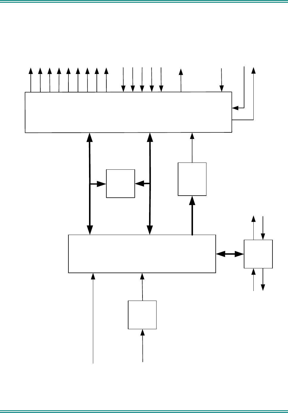
3.4 CONTROL
Refer to Figure 3-4.
3.4.1 DSP and PLA
The SRM9000 transceiver operates under the control of a DSP (U201) and PLA (U300) combination that, together
with a number of other dedicated devices, perform all the operational and processing functions required by the
radio. The PLA is configured by the DSP under software control to provide the following functions:
• Channel set-up of all operating frequencies
• Modulation processing and filtering
• De-modulation processing and filtering
• Tx power output reference
• Modulation Balance adjustment
• Receiver front-end tuning
• Serial communications with alignment tool, microphone and control head
• Modem functionality for data modulation
• All signalling / CTCSS generation and decoding
• Receiver muting control
• TCXO/ Alternate TCXO select
• RSSI / AGC control
• AFC
• Tx / Rx switching and PTT control
• PLL lock detect
• Audio switching
• Power On/Off control
• Interface functionality with Option Boards and External Devices
• Battery voltage and Tx current monitor
3.4.2 PLA PWM
The PLA must supply several analog signals to control radio tuning. It does this with several Pulse Width
Modulated (PWM) outputs.
The front-end tune signals (TUNE1 and TUNE2) originate from the PLA in the form of PWM signals. The values
for these signals are stored in flash memory from radio alignment and are selected depending on the channel that
the radio is currently tuned to. The PWM signals are integrated by RC networks to provide the analog tuning
voltages for the varicap tuning diodes.
Other analog PWM derived signals used are transmitter power (TX_PWR), PLL varicap bias (VCAP_ADJ),
receiver IF gain (IF_GAIN), Automatic Frequency Control (AFC), AFC Switched (AFC_SW), VCO automatic level
control (VCO_ALC) and modulation balance (MOD_BAL).
Analog inputs are monitored by four comparators comprising U301A-D and a ramp generator, the ramp being
derived from a PWM signal from the PLA.

SRM9000X8 800MHz SERVICE MANUAL
© TMC Radio 2008 page 30 TNM-M-E-0022 Issue 1
Analog voltages to be monitored such as PLL Loop Voltage (LOOP_VOLTS), battery voltage (BAT_SENSE),
transmitter current (CURRENT_SENSE) and external sense (EXT_SENSE) are connected to the inverting inputs.
The analog voltages are compared with the ramp voltage as they increase, and the comparator switches at the
point where the input voltage exceeds the ramp. The PLA compares the time at which this occurs with the PWM
signal and converts it to a binary value.
3.5 MEMORY
Memory consists of the internal DSP memory and an external 8MB non-volatile Flash Memory (U202). When
power is off, all program SW and data are retained in Flash Memory. At power-on, a boot program downloads the
DSP and PLA SW from Flash Memory to their internal RAMs for faster program execution and access to data. PLA
SW is loaded by the factory into the Flash Memory and can be updated via the Alignment Tool. DSP SW
comprises Start-up code that is also loaded by the factory. High-level software comprising Operational Code and
Customer Configuration are loaded at distribution centres and are loaded via the FPP Programmer.
SRM9000X8 800MHz SERVICE MANUAL
© TMC Radio 2008 page 31 TNM-M-E-0022 Issue 1
DSP
U201
Synthesiser
U721
PLA
U300
Reset
U200
Flash
Memory
U202
CODEC
U800
Serial port
Serial port
TX_DATA
RX_DATA
IF_GAIN
TX_Power
1. SPKR_ON
2. PA_ON
3. TX_MODE
4. OPTION ON/OFF
5. PWR_OFF
6. ANALOG GATE CONTROLS
7. SYNTH_FAST
Tune 2
BAT_SENSE
Rx
Audio
Tx
Audio
AFC
AFC_SW
LOOP_VOLTS
EXT_SENSE
1. PTT_IN1
2. PTT_IN2
3. GAIN
4. DC PWR_STATUS
5. PWR_SENSE
Bit
Outputs
CURRENT_SENSE
BAT_SENSE
POWER_SENSE
MOD BAL
Bit
Inputs
LOCK
PWM
Outputs
Sampled Analog Inputs
DSP_CLK
Tune 1
VCAP_ADJ
ALC_SET
Figure 3-4 Controller Block Diagram

SRM9000X8 800MHz SERVICE MANUAL
© TMC Radio 2008 page 32 TNM-M-E-0022 Issue 1
3.6 POWER SUPPLIES
3.6.1 Power On Function
The unregulated 13.8V DC input (13V8_UNSW_F) is routed directly to all high current devices and is then
switched via FET (Q900) to provide BAT_SW supply for all other circuits. The output from Q900 feeds three low
dropout series regulators and switched battery voltage. These regulated supplies power auxiliary supplies as well
as the negative and positive voltage generators. The radio ON/OFF function is achieved through Q902, Q908 and
Q909. A low voltage pulse from the control unit or microphone handset PWR ON or PWR OFF momentarily turns
on Q900/Q908 for approximately 1 sec. In this time, the radio DSP samples the PWR_SENSE line and determines
the state of the on-off switch. If the on-off switch is on, the DSP raises the PWR_OFF line and latches the main
FET (Q900) on, which then maintains power to the radio circuitry.
The Power-off operation requires the On-Off switch to be turned off for more than 2 seconds. If the On-Off switch
is sensed going low by the DSP via the PWR_SENSE line, the DSP will save radio settings and then lower the
PWR_OFF line, thereby turning Q900 off.
3.6.2 Power Supplies
The following is a list of the SRM9000 power supplies and some of the devices and circuits they supply.
3.6.2.1 8V Regulator U900
Regulated 8.0V supply (8V RF)
• Tx buffers Q521, Q531a
• VCOs and VCO buffers via active filter Q622
Regulated 8.0V switched supply (5V RX)
• Rx front end
• IF Amplifier
• Various switching functions
3.6.2.2 5V Regulator U901
Regulated 5.0V supply (5V A, 5V D, 5V RF and 5V RFF)
• Synthesizer buffer Q640
• VCO varactor positive supply Q780 to Q783
• TCXOs U711 and U712
• TCXO divider U760
• Rx audio amplifiers U802/U803
• Rx mute switch Q810 to Q813
Regulated 5.0V switched supply (5V TX and Tx PSU+)
• Tx power control U551
• Tx buffers Q501 to Q531a
• Various switching functions
3.6.2.3 3.3V Regulator U912
Regulated 3.3V supply (3V3)
• Reset U200

SRM9000X8 800MHz SERVICE MANUAL
© TMC Radio 2008 page 33 TNM-M-E-0022 Issue 1
• PLA U300
• DSP U201
• Flash U202
• Digital supply for CODEC U800
Regulated 3.3V supply (3C3)
• Analog supply for CODEC U800
Regulated 3.3V supply (3Q3)
• I/Q demodulator U481
Regulated 3.3V supply (3P3)
• Digital supply for PLL U701
Unregulated 13.8V (13V8_UNSW)
• Tx PA module U500
• Antenna changeover switch Q571/572/573
3.6.2.4 2.5V Regulator U903
Regulated 2.5V supply (2V5)
• DSP core U201
• PLA core U300
3.6.2.5 Negative and Positive High Voltage Power Supply U904E/F
• +16V output (+16V) for VCO Varicap tuning drivers
• -12V Output (-12V) for Front end Varicap tuning drivers
3.6.2.6 Unswitched Battery (13V8_UNSW_F)
• Rx audio power amplifier U805
• Rx mute switch Q811

SRM9000X8 800MHz SERVICE MANUAL
© TMC Radio 2008 page 34 TNM-M-E-0022 Issue 1
4. ALIGNMENT (LEVEL 3 SERVICE ONLY)
4.1 GENERAL
If the radio contains customer configuration data that must be retained, you must first use the SRM/SRP
Personality Programmer (FPP) software to read all radio configuration files and save them on to alternative media
before commencing the alignment procedure.
When the Alignment is completed, use the FPP software to retrieve the stored data and write it back to the radio.
It is preferred that the radio remain installed in its aluminium extruded case throughout this alignment procedure. If
the radio is to be aligned when removed from the case, a temporary heat sink must be fitted under the Transmitter
PA module and the receiver output must be kept below 100mW.
Note. Final Tx power adjustments must be performed with the radio board installed in the chassis.
Each transceiver will need to be individually tested and to have the resultant calibration data stored within it. This
data cannot be modified by the user or by the normal customisation (eg. channel frequency, selcall ID etc.)
process. It is set during the manufacturing process and may be modified for maintenance purposes by use of the
Alignment Tool.
For customer channels between each pair of test frequencies, an interpolation is automatically carried out to
determine the correct DAC values at the relevant frequency for the above calibration parameters.
For all of the following alignment procedures it is assumed that the radio is connected to a Comms. Analyser or
equivalent collection of test equipment. The alignment is performed at room temperature, with a 50Ω termination
on the antenna connector and with a power supply set to give 13.2V at the radio connector.
Warning
The RF power output from the transmitter during these tests can cause burns and can be dangerous to
some discrete items of test equipment, hence power attenuators may be needed. Also the heat generated
inside the radio after a long period of transmission can be hazardous.
Caution
Preparing the radio for alignment will erase from the radio all customer PMR and Trunking
configuration data (channel, signalling information etc). The only data retained by the Alignment
Tool is the factory alignment data for the radio (DAC settings for Tx power, front-end tuning, etc).
Using the Alignment Tool will allow changes to the original factory alignment and will invalidate
all warranties and guarantees unless performed by an authorised level 3 service centre.
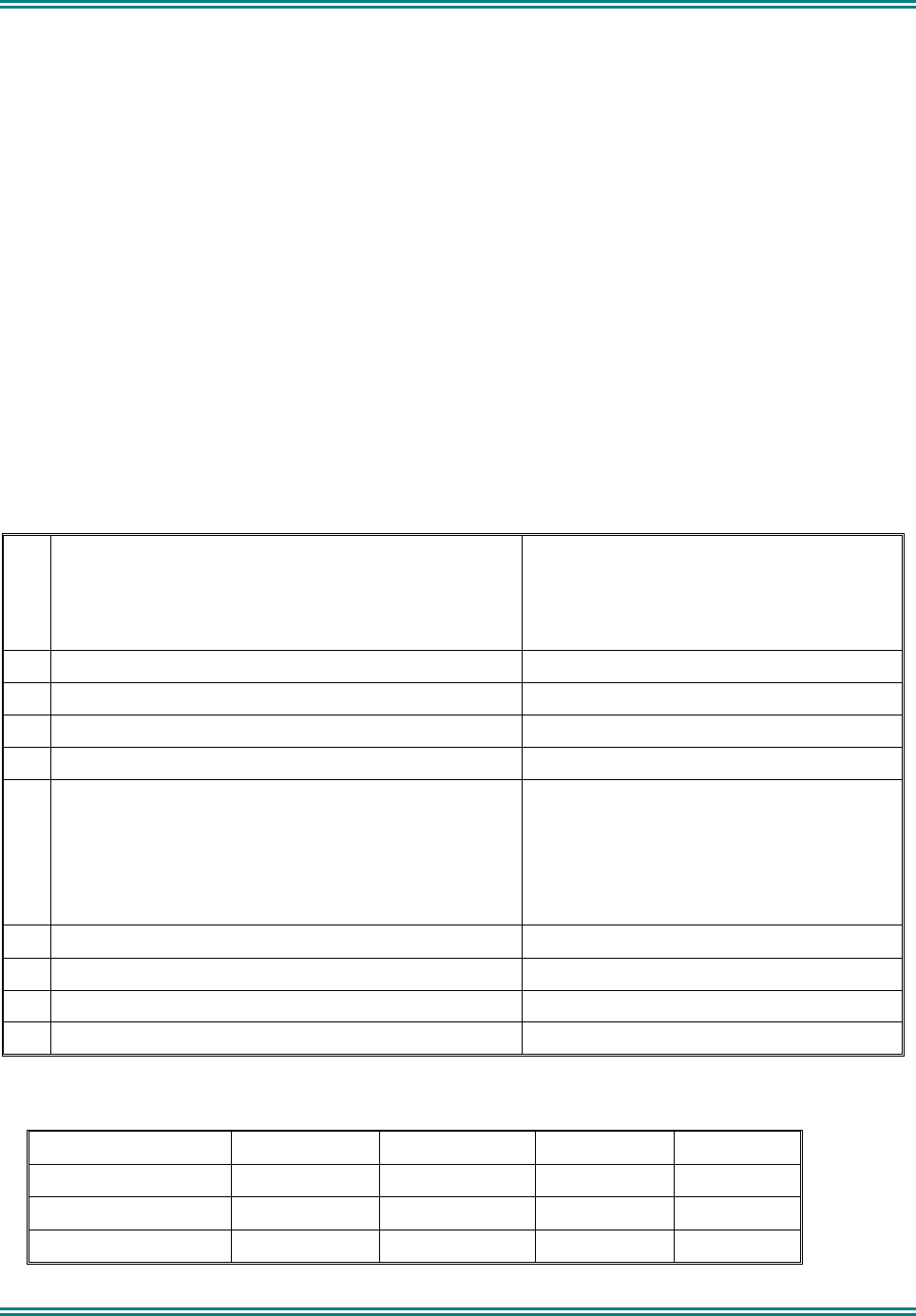
SRM9000X8 800MHz SERVICE MANUAL
© TMC Radio 2008 page 35 TNM-M-E-0022 Issue 1
Calibration sequence
On a set that has not previously been calibrated or in which the calibration has been corrupted, preset parameters
should be initially loaded into the radio for optimum alignment, after which the calibration steps must be carried out
in the following order. These preset parameters may be obtained by reading a previously aligned radio or by
loading predetermined default values.
A number of aspects of the radio need to have calibration data determined and stored during manufacture and
subsequently used by the S/W during normal operation. These must be aligned in the following order:
• Tx and Rx VCO
• TCXO’s
• Tx power
• VCO ALC
• Tx modulation (deviation and then mod balance)
• Rx and Tx filter tuning
• Rx mute
• RSSI
• Tx Current Limit
4.1.1 Test Equipment
1 Radio transceiver test set CMS-50 Comms. Analyser or similar.
Note. For alternative equipment, the Mod
Balance test requires internal DC coupling
between the demodulated signal and
demodulation output connector.
2 Variable DC power supply 10.8V to 16.3V current limited to 7.5 amps.
3 Oscilloscope 20 MHz bandwidth minimum
4 SRM9000 Programming & Alignment Lead P/N MAR-PROGLEAD
5 SRM9000 Radio Test Interface Unit P/N TBD
6 Personal Computer 486 DX 66 or better.
Operating system Windows 95 or later.
Minimum RAM - 16MB.
5MB free hard disk space.
Floppy drive - 1.44MB.
Mouse and serial port required
7 SRM/SRP Alignment Tool Computer Software file
8 SRM/SRP Field Personality Programmer (FPP) Computer Software file
9 SRM9000 Battery Cable
10 RF coax double shielded – N Type male to TNC male.
4.1.2 Alignment Frequencies
Channel 0 1 2 3
Low_RP
High_RP Low_TA High_TA
Rx 851.075 869.975 N/A N/A
Tx 806.025 824.925 851.025 869.925
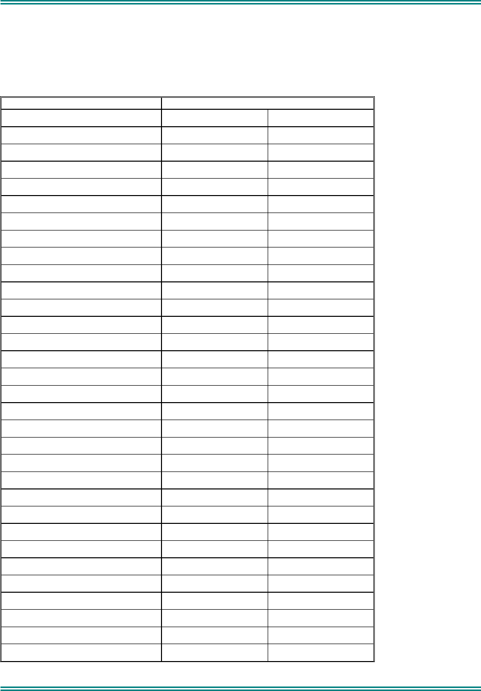
SRM9000X8 800MHz SERVICE MANUAL
© TMC Radio 2008 page 36 TNM-M-E-0022 Issue 1
4.1.3 Preset Parameters
The table below defines the preset alignment settings for the radio DAC’s. These will be programmed into the radio
prior to performing an initial alignment. The Fixed values are not altered by the alignment adjustments whereas the
Adjustable values are used as starting points for alignment where the radio has not been calibrated previously, or
where the calibration has been corrupted.
Variable Name DAC Value
Alignment Adjustable Alignment Fixed
Synth_DAC_TX_Low_RP 193
Synth_DAC_TX_High RP 158
Synth_DAC_TX_Low_TA 106
Synth_DAC_TX_High_TA 66
Synth_DAC_RX_Low 193 (note 1)
Synth_DAC_RX_High 158 (note 1)
Front_End_Tune1_Low 110
Front_End_Tune2_Low 110
Front_End_Tune1_High 185
Front_End_Tune2_High 185
Tx_Filter_Low_RP 60
Tx_Filter_High_RP 90
Tx_Filter_Low_TA 130
Tx_Filter_High_TA 170
Tx_Low_Power_Low_RP 55
Tx_Mid_Power_Low_RP 95
Tx_High_Power_Low_RP 210
Tx_Low_Power_High_RP 55
Tx_Mid_Power_High_RP 95
Tx_High_Power_High_RP 210
Tx_Low_Power_Low_TA 55
Tx_Mid_Power_Low_TA 95
Tx_High_Power_Low_TA 210
Tx_Low_Power_High_TA 55
Tx_Mid_Power_High_TA 95
Tx_High_Power_High_TA 210

SRM9000X8 800MHz SERVICE MANUAL
© TMC Radio 2008 page 37 TNM-M-E-0022 Issue 1
Variable Name DAC Value
Alignment Adjustable Alignment Fixed
VCO_Mod_Limit_Low_RP 14000
VCO_Mod_Limit_High_RP 16500
VCO_Mod_Limit_Low_TA 18300
VCO_Mod_Limit_High_TA 19000
Modulation_Bal_Low_RP 40
Modulation_Bal_High_RP 80
Modulation_Bal_Low_TA 105
Modulation_Bal_High_TA 125
VCO_ALC_Low_RP 75
VCO_ALC_High_RP 80
VCO_ALC_Low_TA 95
VCO_ALC_High_TA 100
Sq_Upper_Threshold 2600
Sq_Lower_Threshold 1000
TCXO 14800
Alternate TCXO 6000
CGF_Current 15
CPG_Current 5
CPT_Timer 6.666
PA_On_Timer 8
CPT2_Timer 255
CPG2_Current 0
Tx_Current_Limit 44 (typ)
Power_Ramp_High_Power_Up_0 0
Power_Ramp_High_Power_Up_1 67
Power_Ramp_High_Power_Up_2 67
Power_Ramp_High_Power_Up_3 215
Power_Ramp_High_Power_Up_4 215
Power_Ramp_High_Power_Up_5 215
Power_Ramp_High_Power_Up_6 215
Power_Ramp_High_Power_Up_7 215
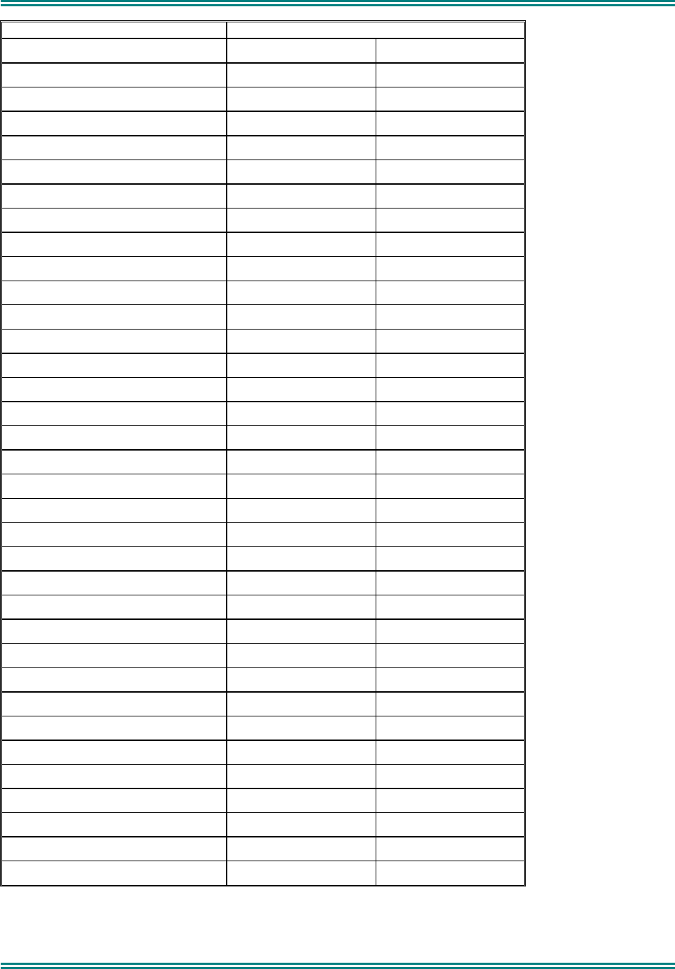
SRM9000X8 800MHz SERVICE MANUAL
© TMC Radio 2008 page 38 TNM-M-E-0022 Issue 1
Variable Name DAC Value
Alignment Adjustable Alignment Fixed
Power_Ramp_High_Power_Up_8 215
Power_Ramp_High_Power_Up_9 215
Power_Ramp_High_Power_Down_0 215
Power_Ramp_High_Power_Down_1 158
Power_Ramp_High_Power_Down_2 96
Power_Ramp_High_Power_Down_3 46(abs)
Power_Ramp_High_Power_Down_4 0
Power_Ramp_High_Power_Down_5 0
Power_Ramp_High_Power_Down_6 0
Power_Ramp_High_Power_Down_7 0
Power_Ramp_High_Power_Down_8 0
Power_Ramp_High_Power_Down_9 0
Power_Ramp_Low_Power_Up_0 10(abs)
Power_Ramp_Low_Power_Up_1 56
Power_Ramp_Low_Power_Up_2 56
Power_Ramp_Low_Power_Up_3 56
Power_Ramp_Low_Power_Up_4 56
Power_Ramp_Low_Power_Up_5 56
Power_Ramp_Low_Power_Up_6 56
Power_Ramp_Low_Power_Up_7 56
Power_Ramp_Low_Power_Up_8 56
Power_Ramp_Low_Power_Up_9 56
Power_Ramp_Low_Power_Down_0 56
Power_Ramp_Low_Power_Down_1 26(abs)
Power_Ramp_Low_Power_Down_2 0
Power_Ramp_Low_Power_Down_3 0
Power_Ramp_Low_Power_Down_4 0
Power_Ramp_Low_Power_Down_5 0
Power_Ramp_Low_Power_Down_6 0
Power_Ramp_Low_Power_Down_7 0
Power_Ramp_Low_Power_Down_8 0
Power_Ramp_Low_Power_Down_9 0
Note 1. These values are automatically set and should equal Synth_DAC_TX_Low_RP and
Synth_DAC_TX_High_RP values respectively.
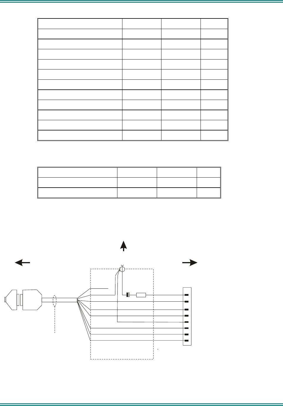
SRM9000X8 800MHz SERVICE MANUAL
© TMC Radio 2008 page 39 TNM-M-E-0022 Issue 1
4.1.4 Alignment Limits
TEST NAME HIGH LIMIT LOW LIMIT UNIT
TCXO Alignment +50 -50 Hz
TX POWER 1.0W 1.06 0.94 W
TX POWER 5W 5.20 4.80 W
TX POWER 27.5W 28.0 27.0 W
VCO MOD LIMIT (Max peak) 2300 2250 Hz
MOD BALANCE +5% -5% Flatness
RX FILTER 1,2 Auto aligned Auto aligned
TX FILTER 1,2,3,4 Preset Preset
RSSI CAL @ -90dBm 2000 500
SQUELCH OPEN 11.5 8.5 dBS
SQUELCH CLOSED 7.0 3.0 dBS
4.1.5 Band specific frequency limits
TEST NAME HIGH LIMIT LOW LIMIT UNIT
VCO - Rx 915.000 896.000 MHz
VCO - Tx 960.000 896.000 MHz
4.1.6 SRM9000 Radio Test Interface Unit
Black
Red
Yellow
Blue
Brown
Orange
Green(4)
White (8)
(Not Used)
+470E White
Green
Mic Audio in
Mic Ground
Ground
Handset AF Output
13.8V Switched
On/Off
Rx Data
Tx Data
8
4
7
6
5
3
2
1
RJ45
PRM80
Programming Cable
P/N 9525-001-00016
BNC (F)
Connector
22uF to 47uF
Tant. or Elect
DB25
Access and modify
cable as shown
9000_49/2
25-9 Way
Adaptor
PC To
SRM9000
S1
A
F Generator
R
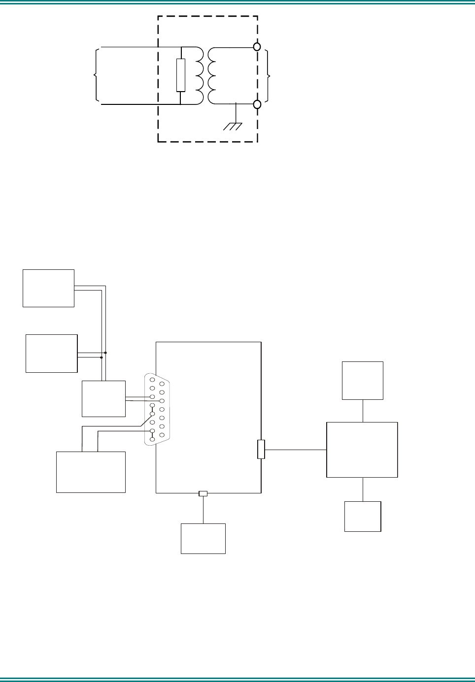
SRM9000X8 800MHz SERVICE MANUAL
© TMC Radio 2008 page 40 TNM-M-E-0022 Issue 1
.
.
.
To
SRM9000 P2
Pins 6 & 13
R = Audio power Load (set as appropriate)
or
Resistor 4R 4W for ½ Bridge Speaker option
Resistor 8R 12W for full Bridge Speaker option
600R 1:1
Line Matching
Transformer
To
Noise & Distortion Meter
&
Oscilloscope
9000_49/3b
R
T1
4.1.7 Test Setup
1. Connect the radio to the test equipment as shown above.
2. Switch on the DC Power Supply.
7
6
5
4
3
2
1
8
15
14
13
12
11
10
9
SRM9000
P2
(DB15M)
PC
SRM9000
Programming
and
Alignment
Breakout
Box
S5
Antenna Skt
S1
RJ45
A
F
Generator
13.8V DC
Power Supply
CRO
9000_49
+-
Radio
Transceiver
Test
Set
Noise &
Distortion
Meter
SRM9000
Speaker O/P
Breakout
Box
Coax
(<200 mm)
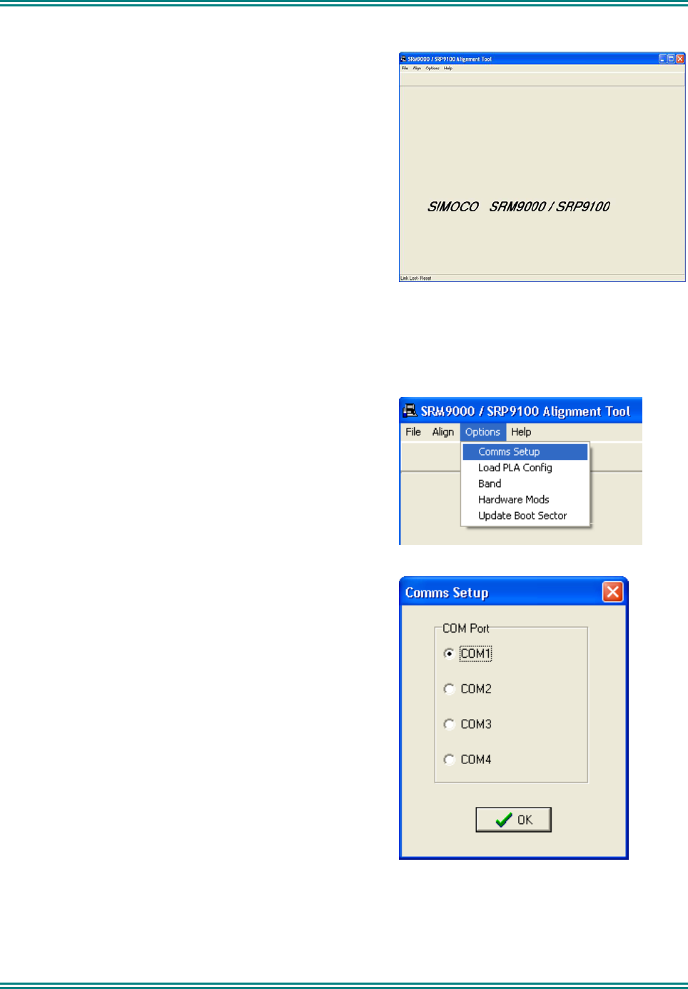
SRM9000X8 800MHz SERVICE MANUAL
© TMC Radio 2008 page 41 TNM-M-E-0022 Issue 1
4.1.8 COMMS Setup
1 Copy the SRM9000 Alignment Tool Computer Software
file to the PC hard drive and run the program
The Alignment Tool Opening Menu is displayed.
2 Go to the Options menu and choose Comms Setup.
3 The Comms Setup dialogue box is displayed.
Select the Comms Port setting appropriate to the
configuration of your PC and choose 9OK.
(Usually COM1)
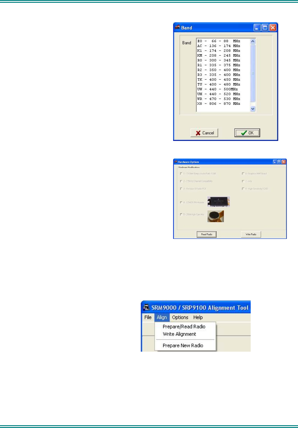
SRM9000X8 800MHz SERVICE MANUAL
© TMC Radio 2008 page 42 TNM-M-E-0022 Issue 1
4.1.9 Band Preparation
1 Go to the Options menu and choose Band. Select
appropriate band and choose 9OK.
4.1.10 Hardware Options Select
1 Options menu choose Hardware Mods.
Press Read Radio.
Tick 9 the box according to the revision as desired as in
the table below.
Press Write Radio.
(Press Read Radio again make sure the selected options
are still ticked ).
4.1.11 Radio Preparation
Radio parameters are to be aligned sequentially as detailed in this procedure.
1 At the Opening Menu, select the Align Menu
and choose Prepare/Read Radio.
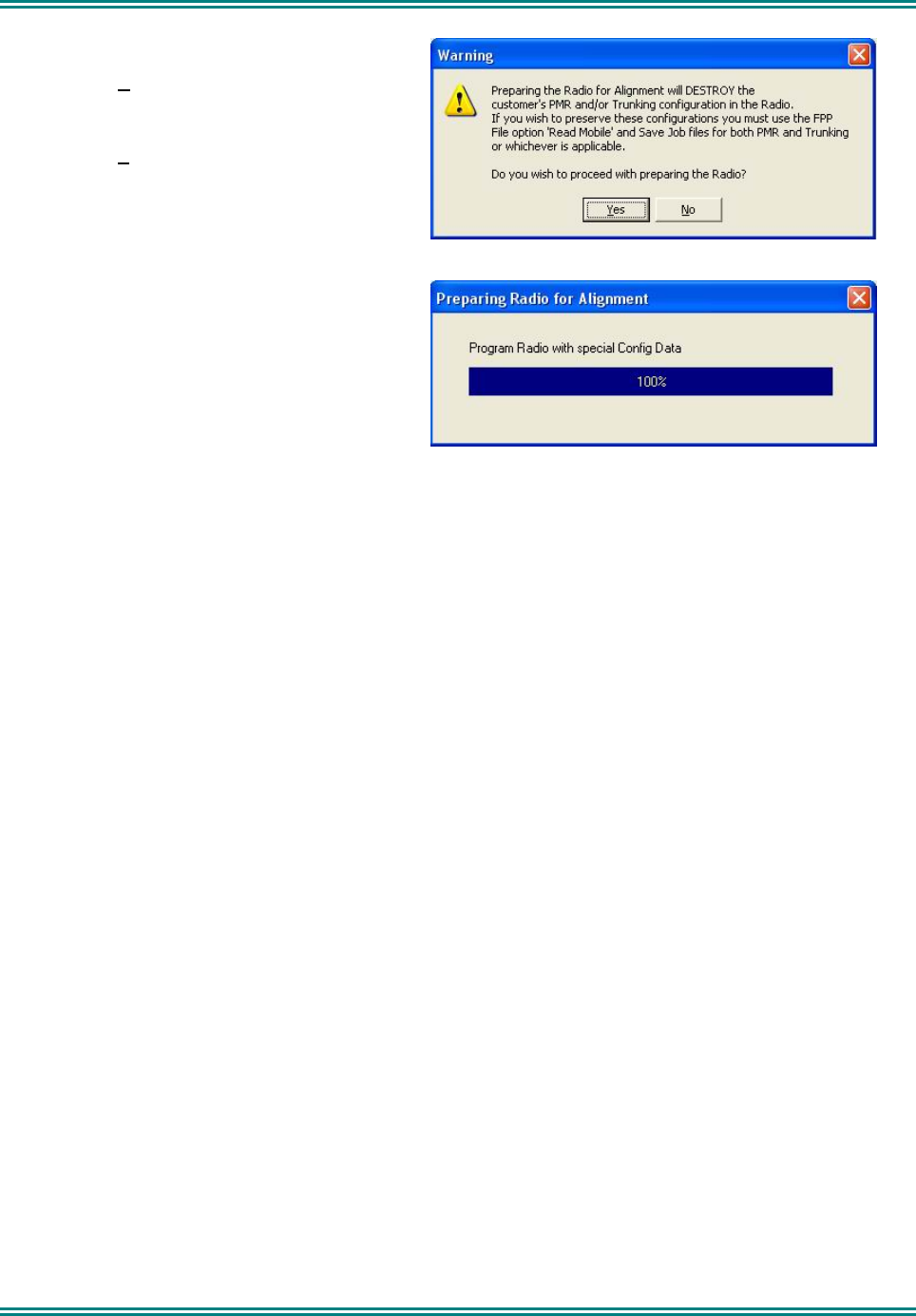
SRM9000X8 800MHz SERVICE MANUAL
© TMC Radio 2008 page 43 TNM-M-E-0022 Issue 1
2 The WARNING is displayed.
Choose No if you want to save the
configuration and use the FPP software to
read and save the data to a file.
Choose Yes if you want to proceed and go to
step 3.
3 The radio alignment data is read (indicated
by percentage bar) and stored.
The test alignment data is downloaded into
the radio.
Note: In test alignment mode the radio is configured only for 12.5 kHz channel spacing. Therefore all alignment
is carried out at 12.5 kHz levels. When the radio is configured with the FPP for other channel spacings,
the deviation related levels are calculated on a per channel basis by the radio software.
4.1.12 ALIGNMENT PROCEDURE
Radio alignment must be done in the sequence detailed in the following paragraphs. This alignment assumes that
the radio is functioning normally.
4.1.13 VCO DAC Alignment
The frequencies generated by the Tx and Rx VCO’s are determined by the synthesiser loop output for fine control
and by a DAC setting for coarse control. The DAC needs calibrating at each of four test frequencies. No calibration
is necessary for the receiver 2nd LO.
During this procedure, the alignment program puts the radio into a special mode in which it ignores the ‘out of
lock’ signal from the synthesiser.
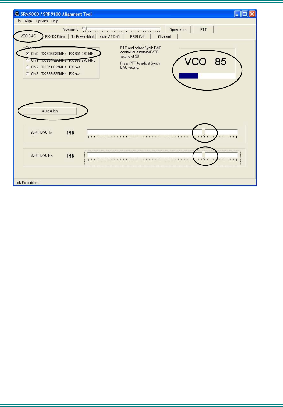
SRM9000X8 800MHz SERVICE MANUAL
© TMC Radio 2008 page 44 TNM-M-E-0022 Issue 1
Calibration procedure
1 Select the VCO DAC page.
2 Select PTT with no modulation.
3 Select Auto Align. The Synth DAC Tx slider will automatically adjust its value for each transmitter
alignment frequency to set the VCO loop filter value between 87 and 93.
4 The Synth DAC Rx slider must be set to the same Tx value for Channels 0 and 1 only.
This is automatically set when Auto Align is selected.
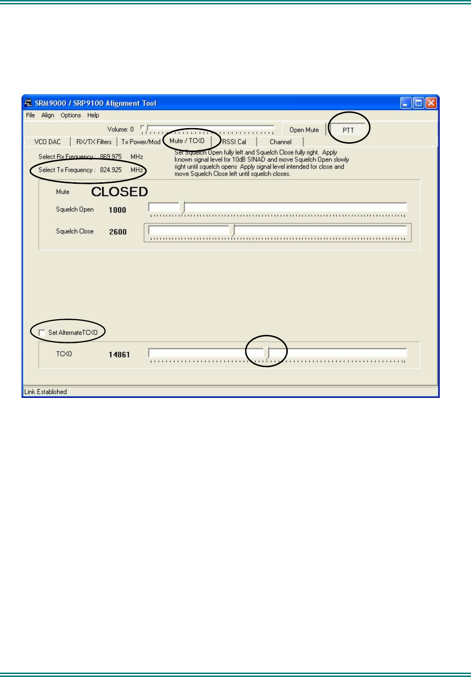
SRM9000X8 800MHz SERVICE MANUAL
© TMC Radio 2008 page 45 TNM-M-E-0022 Issue 1
4.1.14 TCXO DAC Alignment
General
The optimum radio case temperature for TCXO alignment is around 25°C although a temperature between 20°C
and 30°C is permissible. If the radio has been allowed to exceed this range during previous transmit
cycles, it should be allowed to cool until it is within the permissible range.
Calibration procedure
1 Select the Mute/TCXO page.
2 Select PTT.
3 Adjust the TCXO slider to ensure that the transmit frequency error is within 50Hz of 824.925000MHz.
4 Select “Set Alternate TCXO”.
5 Adjust the TCXO slider to ensure that the transmit frequency error is within 50Hz of 824.912500MHz.
6 Deselect “Set Alternate TCXO”.
7 Deselect PTT.
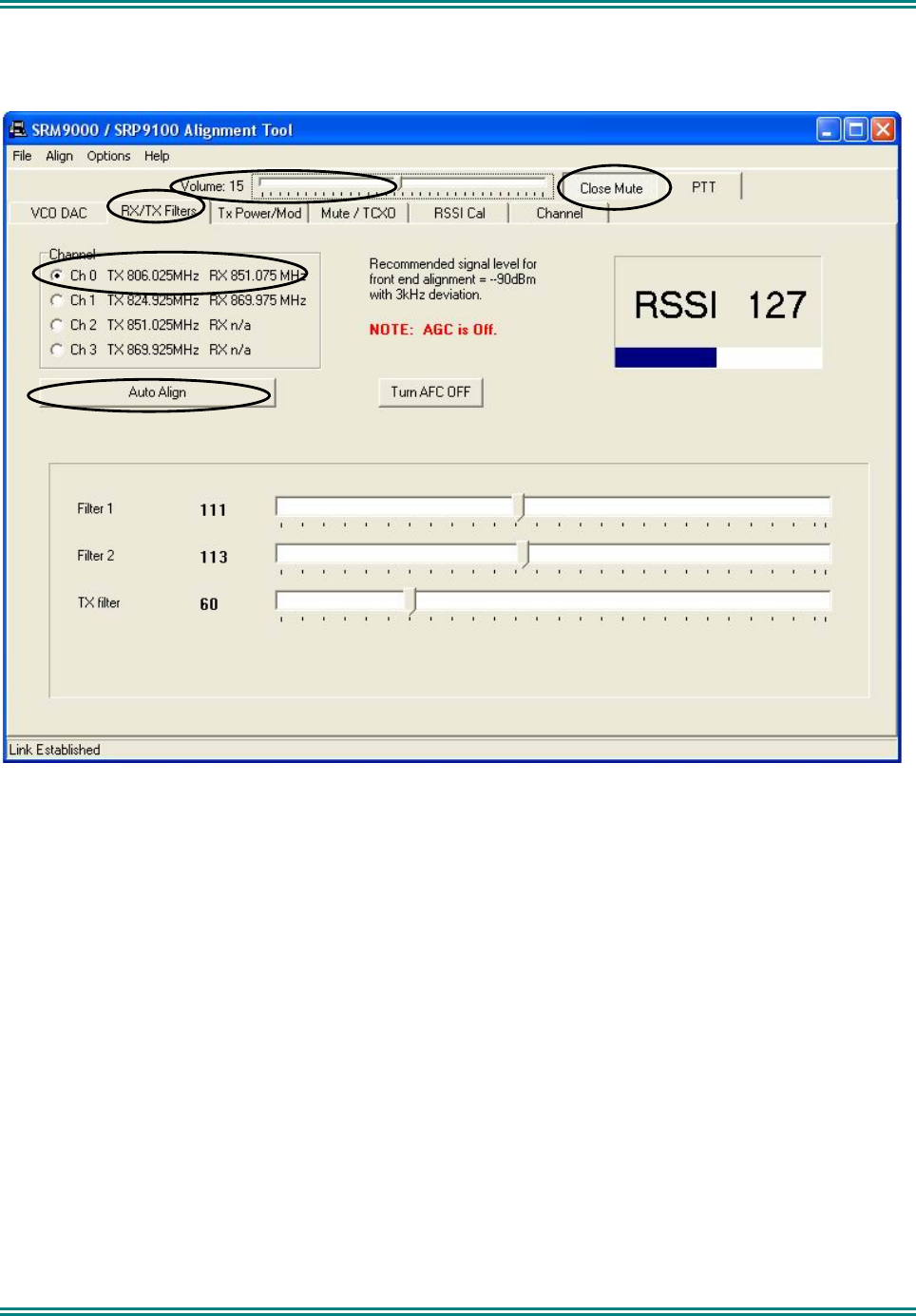
SRM9000X8 800MHz SERVICE MANUAL
© TMC Radio 2008 page 46 TNM-M-E-0022 Issue 1
4.1.15 Rx Front End DAC Alignment
Calibration procedure
1 Ensure that the TCX0 Alignment has been done before proceeding with this section.
2 Select the Rx/Tx Filter page.
3 Select Open Mute.
4 Set the Volume slider to 15.
Speaker audio should now be visible on the Scope. If required readjust the Volume slider to a suitable
level.
5 Select Channel 0
6 Set the Signal Generator to the Channel 0 carrier frequency, with a 1000Hz modulation signal, a
deviation of ±3 kHz and a RF level of -90dBm.
The RSSI bar-chart display should now be (typically) well above a reading of 20.
7 Select Auto Align.
The front end will be tuned automatically and finish with an RSSI reading of typically around 150..
8 Change deviation to 1.5kHz.
9 Verify that the receiver sensitivity is better than -117.5dBm for 12dB SINAD. (Sensitivity is typically -
120dBm).
10 Repeat Steps 7 to 9 for Channel 1.
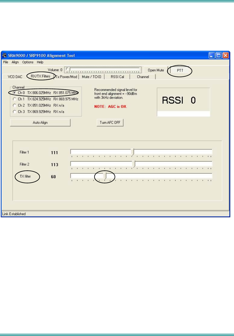
SRM9000X8 800MHz SERVICE MANUAL
© TMC Radio 2008 page 47 TNM-M-E-0022 Issue 1
4.1.16 Tx Filter DAC Alignment
General
This filter should be set so that the Tx spurious emission at 180MHz above the carrier frequency is adequately
notched.
Calibration procedure
Note. This step is only required if Tx Filter DAC values have been corrupted.
1 Select the Rx/Tx Filter Page
2 Select Channel 0
3 Set DAC to preset value as per Section 2.13.
4 Repeat for the next three channels 1, 2 and 3.
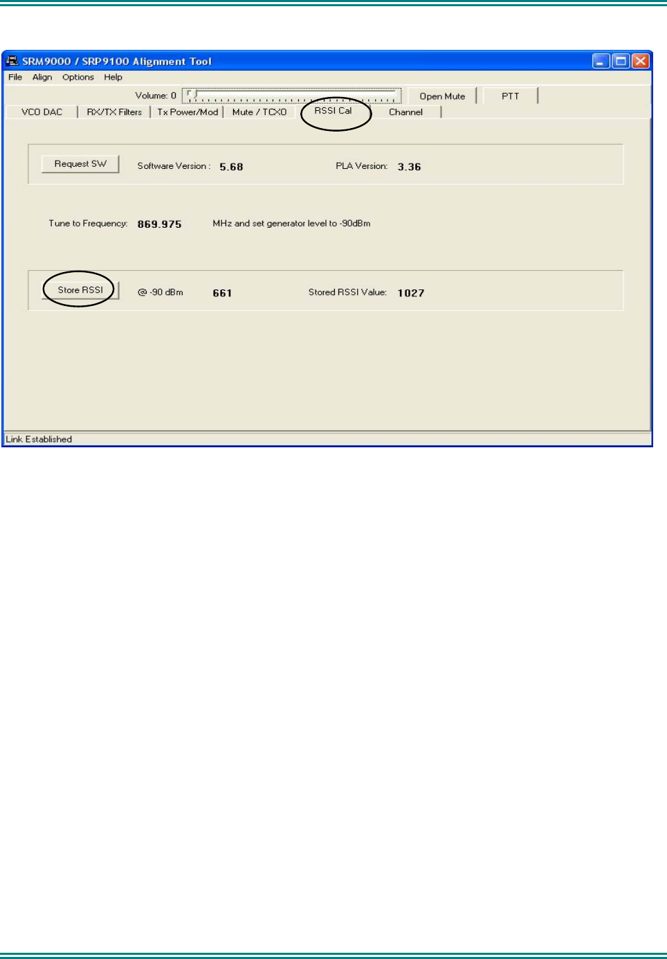
SRM9000X8 800MHz SERVICE MANUAL
© TMC Radio 2008 page 48 TNM-M-E-0022 Issue 1
4.1.17 RSSI Calibration
Calibration procedure
1 Select the RSSI Cal page.
2 Set the Signal Generator for a RF output level of -90dBm and 3kHz deviation at the specified
frequency.
3 Activate the Store RSSI button.
The receiver RSSI threshold setting is calibrated.
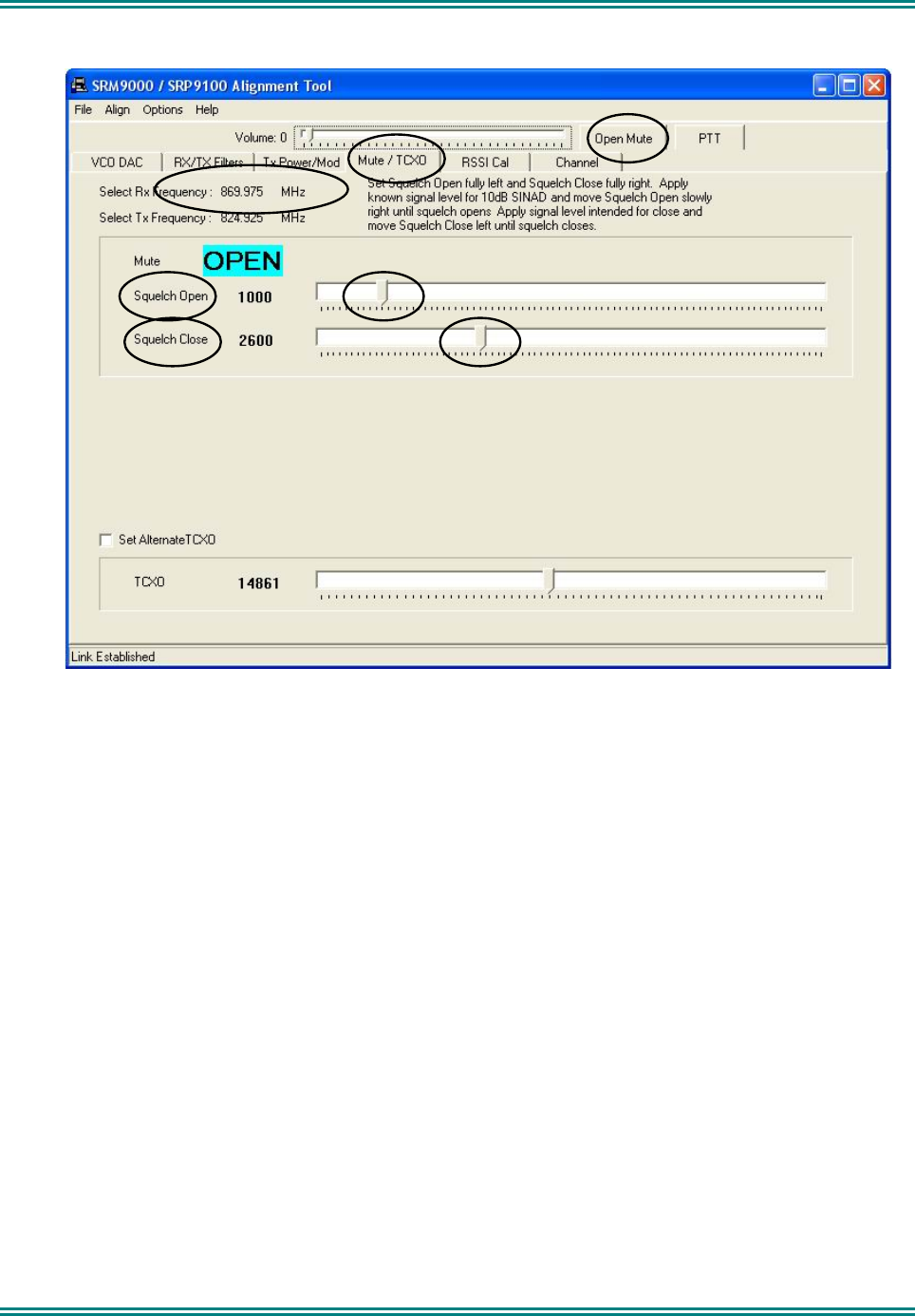
SRM9000X8 800MHz SERVICE MANUAL
© TMC Radio 2008 page 49 TNM-M-E-0022 Issue 1
4.1.18 Mute DAC Adjustment
Note. This adjustment has default setting of 1000/2600 and should not need changing except for specific
requirements.
Calibration procedure
1 Select the Mute/TCXO page and select Open Mute.
2 Set the RF signal generator to the receiver alignment frequency, and adjust the RF level such that the
desired mute opening SINAD (typically 10dB SINAD) is achieved.
3 Select Close Mute and remove the RF input from the radio.
4 Set the Squelch Open and Squelch Close sliders to the fully left position. This ensures the receiver
will be muted.
5 Set the Squelch Close slider to the fully right position.
6 Reconnect the RF input to the radio.
7 Adjust the Squelch Open slider to the right until the mute opens.
8 Reduce the Signal Generator output level by approximately 2dB (or by an amount equal to the
desired mute hysteresis level).
9 Adjust the Squelch Close slider to the left until the mute closes.
10 The mute should now open and close at the desired RF levels.
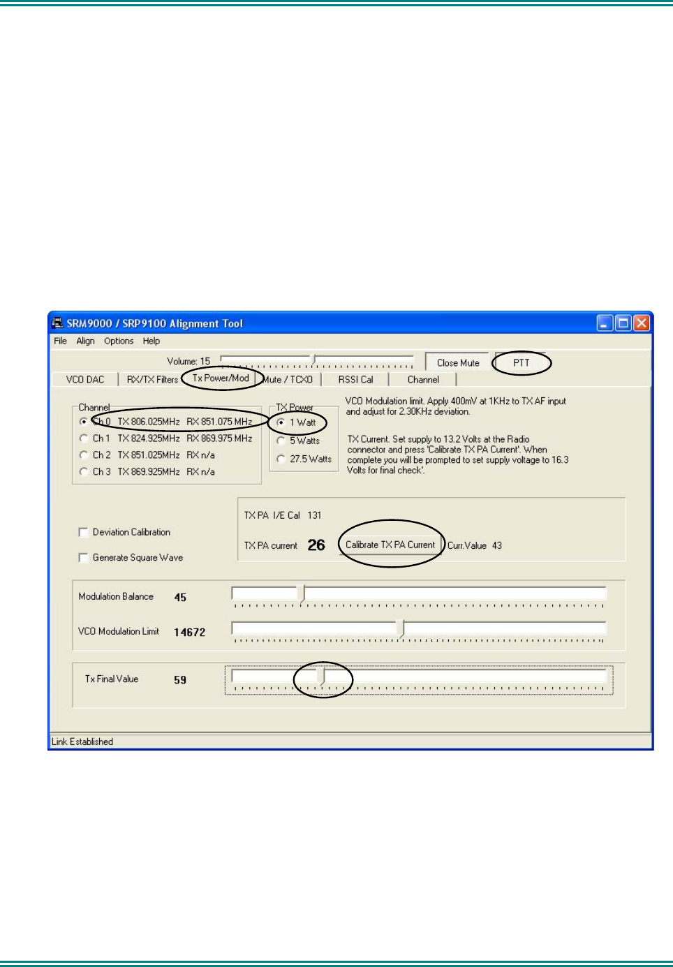
SRM9000X8 800MHz SERVICE MANUAL
© TMC Radio 2008 page 50 TNM-M-E-0022 Issue 1
4.1.19 Tx Power DAC Alignment
General
The transmitter output power can be programmed to three power ranges: 1W, 5W and 27.5W by the
appropriate setting.
Note 1: Care should be taken not to set the output power and hence supply current to excessive levels, ie.
above 30W or 7.5A, since the higher heat dissipation involved may effect component reliability.
Note 2: Also, the antenna connector should be terminated directly into the Comms. Analyser for this test to
minimise VSWR effects that could affect settings.
Note 2: Repeat the following steps as quickly as possible to avoid excessive heating the radio, which may
affect calibration.
Note 3: The Tx Current Limit setting provides a maximum current limit into the RF PA module to protect it in
the event of high dissipation as a result of inadequate drive power being applied relative to the Power DAC
setting or high VSWR’s
Calibration procedure
1 Select Tx Power/Mod page.
2 Select Channel 0.
3 Select the 1W power level.
4 Press the PTT button.
5 Adjust the Tx Final Value slider for a power output of 1W.
6 Repeat step 5 for the remaining 3 Channels (1, 2, & 3).
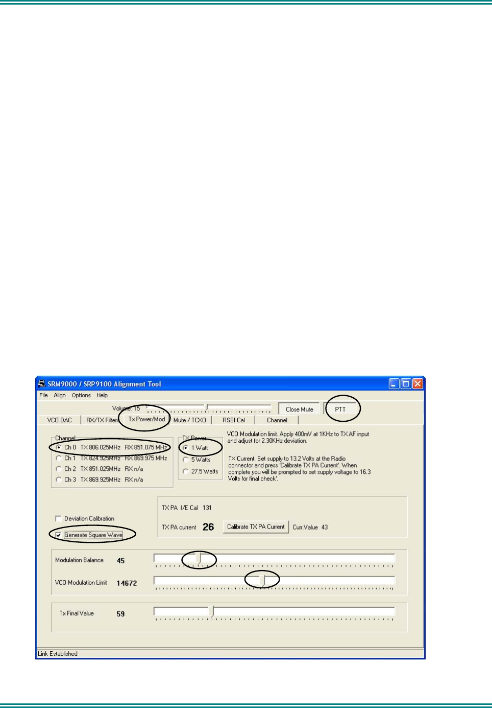
SRM9000X8 800MHz SERVICE MANUAL
© TMC Radio 2008 page 51 TNM-M-E-0022 Issue 1
7 Select the 5W power level.
8 Adjust the Tx Final Value slider for a power output of 5W.
9 Repeat step 8 for the remaining 3 Channels (2, 1& 0).
10 Select the 27.5W power level.
11 Adjust the Tx Final Value slider for a power output of 27.5W.
Note that the supply current is less than 7.5A.
12 Repeat step 11 for the remaining 3 Channels (1, 2, & 3).
13 Press Calibrate TX PA Current button and follow the prompt to automatically set the maximum
current limit.
14 The PTT will automatically dekey after this procedure.
4.1.18 Tx Modulation DAC Alignment
All microphone levels are referenced to the audio level output displayed on the Comms. Analyser and based on <10Ω
source impedance.
NOTE: This audio signal is fed to the radio input via a series 470Ω resistor and 47uF capacitor in the Audio/ Serial
Interface Adaptor.
General
Dual point modulation is used and there are two settings that need adjusting to meet deviation requirements. The
modulation alignment is set up for 12.5kHz channel spacing. For customer configurations of other channel
spacings, the modulation alignment is automatically adjusted for those settings.
Note that when measuring deviation at 60% MSD the average of the + and − readings should be used. When
measuring maximum deviation, the higher of the + and – readings should be used.

SRM9000X8 800MHz SERVICE MANUAL
© TMC Radio 2008 page 52 TNM-M-E-0022 Issue 1
Calibration procedure
1 Select Tx Power/Mod page.
2 Select Channel 0.
3 Select the 1W power level.
4 Set the microphone input signal from the Audio Generator to 1000Hz at 400 mV RMS.
5 Select PTT and adjust the VCO Modulation Limit DAC to give a maximum peak deviation of 2.30kHz.
6 Reduce the microphone input level to 40mV RMS and check that the deviation is within the range ±1.25
kHz to ±1.75 kHz.
7 Repeat steps 5 to 6 inclusive for the remaining three Channels (1, 2, & 3).
8 Remove the microphone audio input signal
9 Select the Generate Square Wave function.
10 While viewing the de-modulated signal on the transceiver test set oscilloscope, set to DC coupling,
adjust the Modulation Balance slider for the best square wave symmetry.
Refer to Note below
11 Repeat steps 9 to 10 inclusive for the remaining three Channels (2, 1 & 0).
12 Release the PTT button.
Note: The FM demodulator on the measuring equipment also requires DC coupling for this test to provide
correct results. If an HP8920A is used, the top and bottom of the square wave must be set with a 16.6%
negative slope.
ie. For a waveform of 4 divisions p-p (neglecting overshoot) the slope should be adjusted to 0.3 divisions.
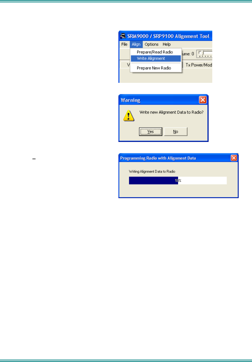
SRM9000X8 800MHz SERVICE MANUAL
© TMC Radio 2008 page 53 TNM-M-E-0022 Issue 1
4.1.20 PROGRAMMING ALIGNMENT DATA
When all channels have been aligned the radio is programmed with the new alignment data:
1 Select Align and choose Write Alignment.
2 A warning message is displayed.
3 Choose Yes.
New alignment data is written to the radio.
4.1.21 CUSTOMER RADIO PERSONALITY DATA
If the Customer Radio Personality Data was saved as a separate file, use the FPP Programmer to write this data to
the radio.
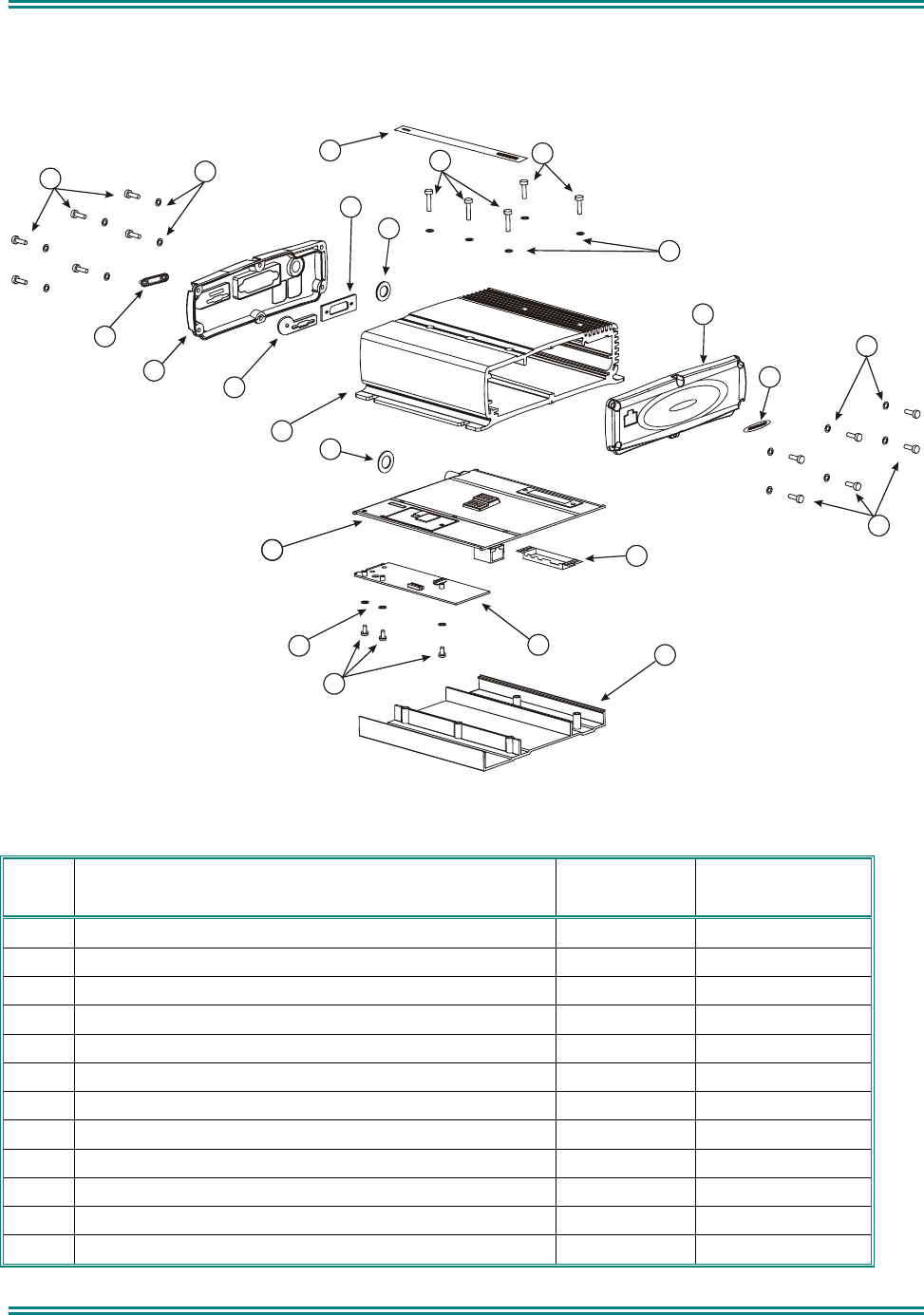
SRM9000X8 800MHz SERVICE MANUAL
© TMC Radio 2008 page 54 TNM-M-E-0022 Issue 1
5. REPLACEABLE PARTS
11
2
3
4
4
56
7
8
9
10
11
11
11
12
14
13
15
16
11
18
17
19
Figure 5-1 Replaceable Parts
5.1 REPLACEABLE PARTS
Ident Description Quantity per
Assembly Part Number
1 Radio Board Assembly X8 Band 1 6102 359 6232
2 Extrusion Main Body Macom 1 6102 310 01452
3 End Cap, Rear, P25 Option 1 6102 310 00532
4 Screw End Cap 12 3513 993 85009
5 Screw Tray Retention M3 x 16 Zinc 3 3513 993 57117
6 Screw Tray Retention M3 x 12 Black 2 6102 700 00081
7 Label Transceiver Top Macom 1 6102 303 00242
8 End Cap, Front 1 3513 903 91072
9 Label End Cap, Front Macom 1 6102 303 00251
10 Inner Tray 1 3513 901 70083
11 Washer Fibre 20 3513 907 30241
12 Washer Seal Antenna Connector 1 3513 907 3255A
SRM9000X8 800MHz SERVICE MANUAL
© TMC Radio 2008 page 55 TNM-M-E-0022 Issue 1
Ident Description Quantity per
Assembly Part Number
13 Gasket D Connector 1 3513 902 1082A
14 Gasket Antenna Connector 1 3513 902 10651
15 MAB-2 Option Board- Programmed 1 6102 359 6213
16 Screw Option Board M3 x 6 3 6102 700 00071
17 Dust Cap P25 Option Connector 1 6102 310 01222
18 Gasket P25 1 6102 310 00812
19 Tx PA Shield cover 1 6102 310 01201
DC Power Cable Macom 1 6102 350 13591
RJ45 Connector, S1 1 6102 621 00121
DB15 Connector, P2 1 3513 993 02063
Antenna TNC connector, S501 1 6102 310 01431
Audio PA Module U805 1 3513 999 52036
Voltage Regulator U900, U901, U912 1 6102 822 00121
Voltage Regulator U903 1 6102 822 00161
Temperature Controlled Crystal Oscillator, U711 & U712 1 6102 922 00011
Transient Suppressor Diode, D900 1 6102 012 00031
Transmit Receive Switch, Q541 1 3513 999 00006
ON/OFF FET Q7, Q900 1 6102 062 00051
Tx PA Module RA45H8087M-101, U561 1 6102 861 00153
6. SCHEMATICS
6.1 SRM9000 800MHZ RADIO BOARD SCHEMATICS:
Sheet
No. Description
1 Transceiver Block Diagram
2 DSP/Flash
3 PLA
4 Receiver
5 Transmitter
6 VCO
7 Synthesizer
8 Tx/Rx Audio
9 Power Supply
10 I/O Connections
Top Overlay of PCB
Bottom Overlay of PCB
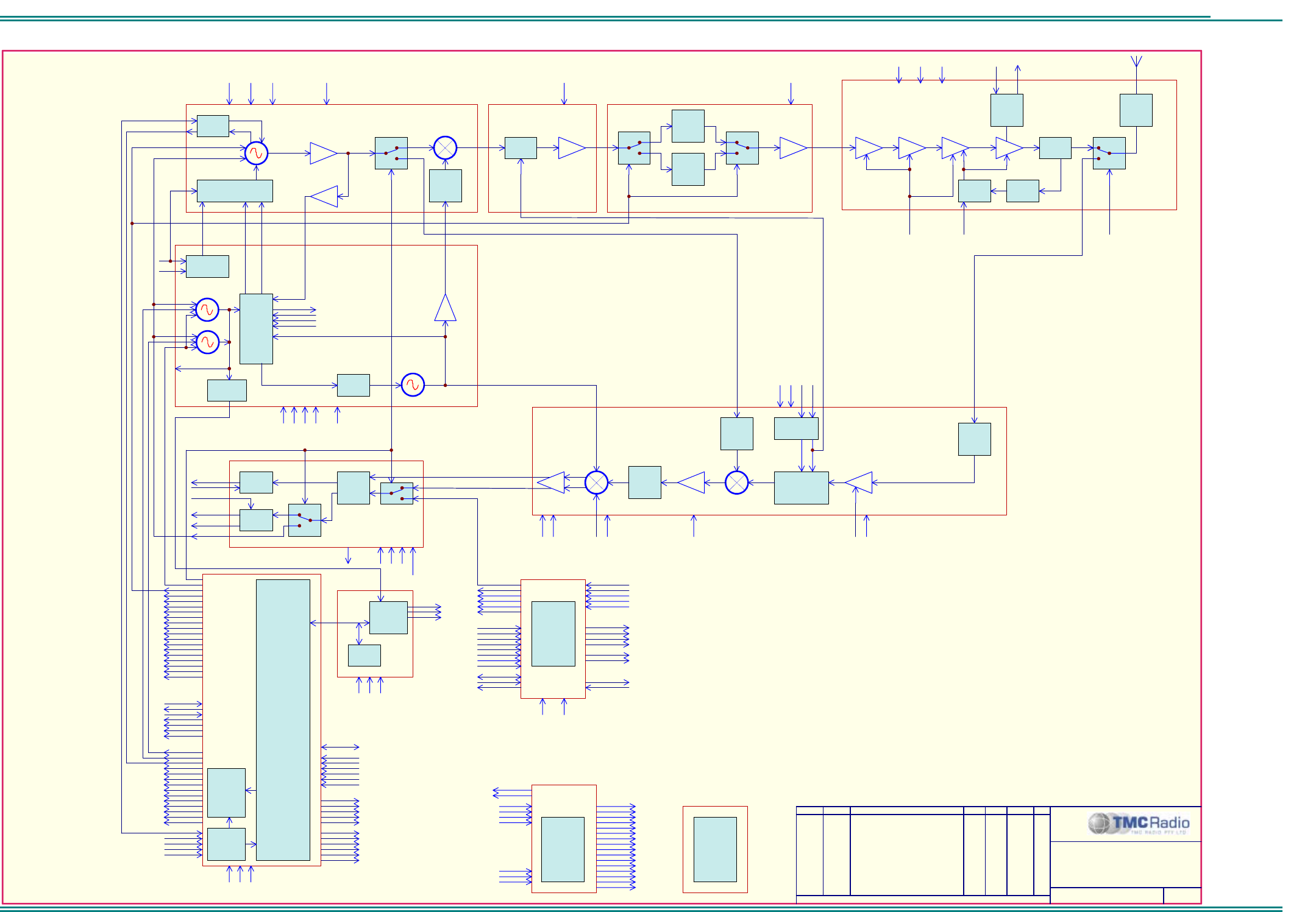
SRM9000X8 800MHz SERVICE MANUAL
© TMC Radio 2008 page 56 TNM-M-E-0022 Issue 1
TNM-M-E-0001
Sheet 1: Transceiver Block Diagram
ORDER DRAWN REMARKS EXAM APPD DATE REV
6102 349 6232
A
ll Rights Reserved
1270 Ferntree Gully Rd Scoresby Australia 3179
C 2006 TMC Radio Pty Ltd ACN 099 952 977
O
SAW
FILTER
851MHz ~
870MHz
(40dB)
VCO BUFFER
SAW
FILTER 806
~ 825MHz
(40dB)
CRYSTAL
FILTER
45MHz
T/A: 941MHz ~ 960MHz
REPEATER: 896 ~ 915MHz
T/A: 851MHz ~ 870MHz
REPEATER: 806 ~ 825MHz
LNA
SAW
FILTER
851MHz ~
870MHz
TUNED FILTER
851MHz ~ 870MHz
30W PA
HARMONIC
FILTER
870MHz
DRIVER
BUFFER
BP FILTER
896MHz ~
915MHz
BP FILTER
90MHz
I/Q DEMODULATOR
AMP 10dB
-9dBm
1dBm
0dBm
DUAL PLL
LMX2485E
Frif=120kH
z
Frrf=480kH
z
LOOP VOLTS
FIN_RF
FIN_IF
PRI
CPP_IF
15.360MHz
PRIMARY TCXOMHz
FIRST MIXER
5V_TX
RX/TX
TUNE_1N
6dBm
FB BUFFER
100mV
200mV
IF AMP
PA_ON
44dBm
45dBm
16dBm
-11dBm 10dBm
0dBm
-9dBm
TA_/REP
6102_349_6232X8052.Sch
6102_349_6232X8042.Sch
6102_349_6232X8062.Sch
6102_349_6232X8072.Sch
5dBm
6102_349_6232X8082.Sch
CODEC
TX_MOD
AUDIO
POWER
AMPLIFIE
I_CH
Q_CH
MIC_AUDIO
AUXILARY
AUDIO
AMPLIFIE
DISC_AUDIO
H'SET_AUDIO
SPKR_AUDIO
6102_349_6232X8032.Sch
PLA
DSP
FLASH
REF_SHIFT
DSP_CLOCK
806MHz~870MHz
(40dB notch)
BUFFER
-6dBm
-5dBm-2dBm
PLL_DATA
6102_349_6232X8022.Sch
6102_349_6232X8092.Sch
POWER
SUPPLIES
6102_349_6232X80102.Sch
EXTERNAL
INTERFACE
AUDIO PROCESSING
RECEIVER SECTION
90MHz VCO
PRIMARY VCO
TX_MIXER
TUNED_FILTER
SWITCHED_FILTERS
ANTENNA SWITCH
6102_349_6232X80112.Sch
HARDWARE
800 MHz BLOCK DIAGRAM
1 of 12
TX_PWR
TX
CURRENT
LIMIT
CURRENT_SENSECURRENT_CAL
PLL_CLK
PLL_STB
TUNE_1
TUNE_2
RX_GAIN
IF_GAIN
POWER
CONTROL
TA_/REP
TUNE_1
TUNE_2
TUNE_3
RX/TX
CURRENT_SENSE
PLL_DATA
PLL_CLK
PLL_STB
8V_RF 13V8_UNSW5V_TX
5V_A3D3 16V
5V_RF
5V_A
3D3
3C3
13V8_SW
3P3
5V_D3V3
5V_D3V3
5V_A
3Q3
5V_D 3D3
5V_D
3A3
13V8_SW
3C3
3P3
3Q3
5V_A
8V_RF
8V_RX
13V8_UNSW 13V8_UNSWF
5V_TX
5V_RX
2V5
2V5
2V5
-12V
16V
-12V
1V65
1V65
3D3
5V_RX
5V_TX
5V_TX
VCAP BIAS
SUPPLY
ADAPTIVE LOOP FILTER
150/600Hz
FAST
LOOP
FILTER
625Hz
INJECTION BUFFER
REFERENCE
BUFFER
4/5 CH A/D
CONVERTER
LOOP_VOLTS
EXT_SENSE
RF_DETECT
ANALOG OUTPUTS 14 CH D/A
CONVERTER
ANALOG INPUTS
DIGITAL OUTPUTS
IF_GAIN
ACCESS_SW
OUTPUT0
RF_GAIN
AUDIO_EN2
AUDIO_EN3
AUDIO_EN4
DATA_EN
MOD_SW
AUDIO_EN1
TX_MODE
SPKR_ON
IGN_SENSE
PWR_SENSE
PTT_IN2
PTT_IN1
LOCK
CURRENT_CAL
PA_ON
MOD_BAL
VCAP_ADJ
REF_SHIFT
TXD1
RXD1
TX_DATA
RX_DATA
SCLK1
CSC_0
MF8??
CCLK
L3C
L3M_A
CLRC
/RESET DIGITAL OUTPUTS
L3D
BUFFER -1dBm
15.359767MHz
SECONDARY TCXOMHz
16V
CPP_RF
VCAP_ADJ
VCAP_BIAS
16V
TX_PWR RX_PON
TX_PON
STBY
TX_PON
RX_PON
STBY
5V_TX
PWR_ON
IGN
PWR_OFF
IGN_SENSE
PWR_SENSE
PWR_OFF
DIGITAL INPUTS
SERIAL I/O
DATA/ADDRESS BUS
ACCESS_ON/OFF
AUDIO_OUT1
AUDIO_OUT2
AUDIO_OUT3
DISC_AUDIO
H'SET_AUDIO
SPKR_AUDIO
13V8_ACCESS_SW
TX_DATA
RX_DATA TXDATA
RXDATA
AUDIO_I/P
OUT#0
IN#0
OUTPUT0
PTT_IN1
MF1~MF24
RX_LO2
RX_LO1
RX_IN
TX_LO2
AF_GAIN
AF_GAIN
MF1~MF24
DIFF AMP
5V_RX
1V65
3P3
VOLTAGE
TRANSLATOR
TUNE_1N
TUNE_2N
PWR_STATUS
BATT_IN
ON/OFF
IGN_SW
13V8_UNSW
PWR_ON
IGN
13V8_UNSWF
EXTERNAL INPUTS
EXTERNAL OUTPUTS
EXTERNAL SERIAL DATA
OUTPUTS
SPKR_AUDIO
INPUTS
I/O
SERIAL DATA
AUDIO_O/P
LOCK
EXT_REF
EXT_REF
EXT_REF
AFC
TX_RF
SPKR_ON
SPKR_ON
5V_RF
.A09.10.06
..CM .. .INITIAL REALEASEU057
SRM9000 RADIO BOARD
BUFFER 5dBm
.B06.02.07
..CM .. .UPDATED TO REV BU089
AFC_SW
VCO ALC
ALC_SET
VCO_BIAS
6102_349_6232X8062.Sch 6102_349_6232X8062.Sch
D/COUPLE
R45dBm
D/COUPLE
R
8V_RF
.C21.06.07
..CM .. .UPDATED TO REV 1U128 .D07.12.07
..CM .. .UPDATED TO REV 2U167
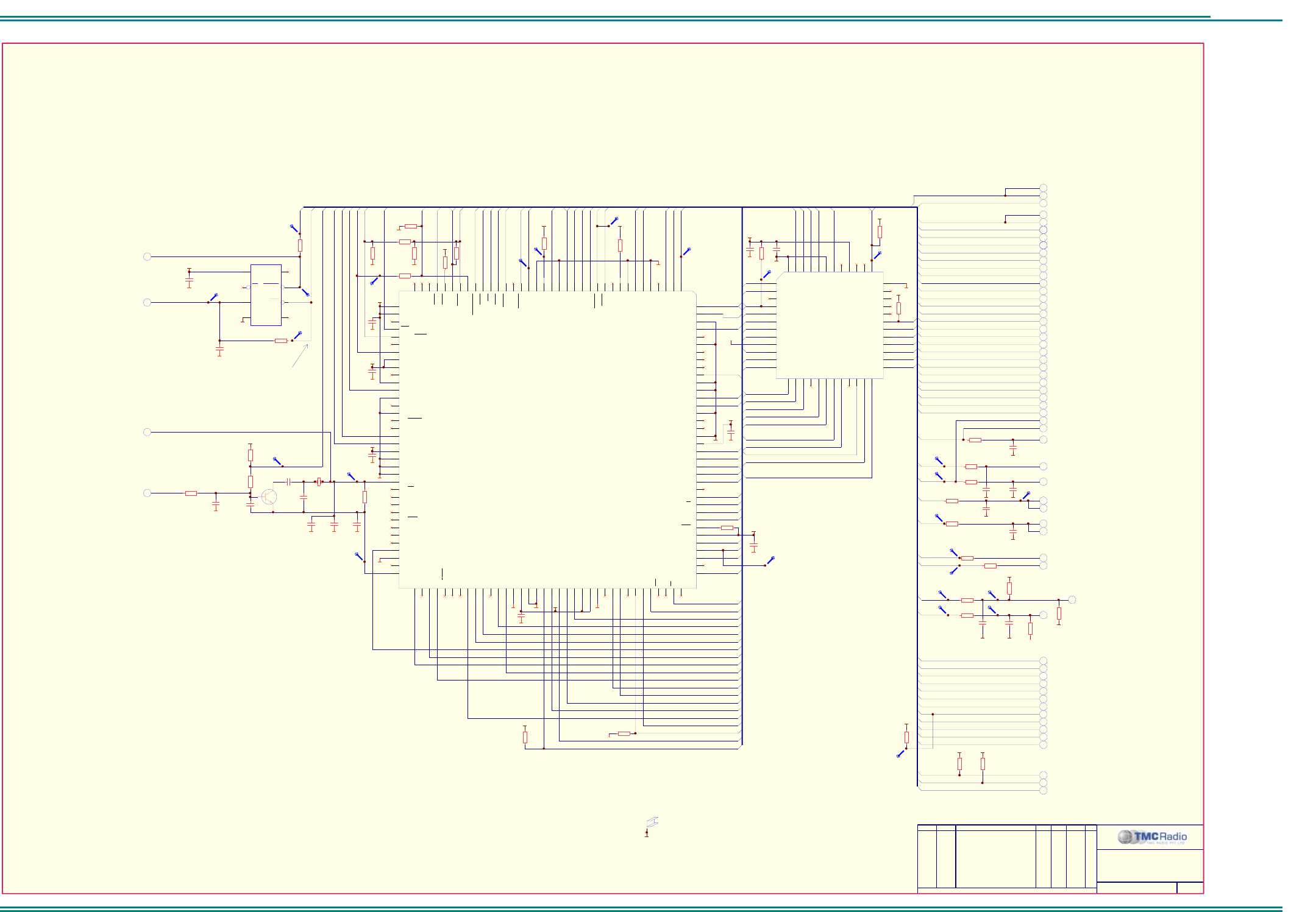
SRM9000X8 800MHz SERVICE MANUAL
© TMC Radio 2008 page 57 TNM-M-E-0022 Issue 1
TNM-M-E-0001
Sheet 2: DSP/ Flash
ORDER DRAWN REMARKS EXAM APPD DATE REV
6102 349 6232
2 of 12
DSP MODULE
SRM9000 RADIO BOARD
TITLE:
A0
A1
A2
A3
A4
A5
A6
A7
A8
A9
A
10
A
11
A
12
A
13
3V3
0VA
A3
A7
/
WR
A9
A
13
A4
D19
/
RESET
A8
A12
A2
A6
D20
A10
D16
A1
R209
10k
R208
10k
R207
10k
C202
100n
R219
N.F.
Q200
N.F.
C206
N.F.
C203
N.F.
R217
100R
0VA0VA
R230
10k
R206
10k
R235
10k
R203
10k
A5
D8
D9
D10
D11
D12
D13
D14
D15
DONE
3V3
0VA
A
11
D16
D17
D18
D19
D20
D21
IRQ8
8
8
9
9
D8
D9
D10
D11
D12
D13
D14
D15
GCLK
/RD
/WR
0VA
0VA
SINT
C204
100n
0VA
C205
N.F.
2V5
R212
N.F.
0VA
R218
680K
2
4
7
Vcc
PFI
RESET
3Gnd
1
5
PFO
MR
8
6
NC
RESET
U200
ADM708SARZ
7
7
7
C200
100n
R225
10k
R222
270R
R223
270R
R221
270R
PLL_STB
C215
33p 0VA
PLL_CLK
PLL_DATA
C216
33p 0VA
C212
N.F.
0VA
R216
N.F.
3
3
3
3
3
3
3
3
3
3
3
3
3
3
3
3
LB_RESET
3
3
3V3
0VA
C211
100n
3V3
0VA
C214
100n
3V3
0VA
C213
100n
0VA
0VA
0VA
0VA
2V5
0VA
C210
100n
3V3
0VA
C209
100n
2V5
0VA
C201
100n
0VA
0VA
PSEL
PSEL
3V33V3
3V3
3V3
3
GDAT
STB
TX_ENABLE
RX_ENABLE
R220
4k7
R224
4k7
3V3
CLK_SHIFT
SOFS
10
3
3
3
3
EBR
ERES
TFS
GSEL
/RESET
ELIN
ELOUT
EINT
EMS
EE
ECLK
RXD
TXD
EBG
RFS
SCLK0
CLKOUT
SOFS
SCLK1
/BR
/BR
/BG
10
10
10
10
10
10
10
10
10
10
10
R201
1k0
/RESET
DR0
DT0
3
NCONFIG
3
3
3
A3
A1
A7
A2
RY/BY#
A3
WE#
A4
A9
A5
A
13
A6
A4
B1
A
17
B2
NC
B3
RESET#
B4
A8
B5
A
12
B6
A2
C1
A6
C2
A18
C3
NC
C4
A10
C5
A14
C6
A1
D1
A5
D2
NC
D3
NC
D4
A11
D5
A15
D6
A0 E1
DQ0 E2
DQ2 E3
DQ5 E4
DQ7 E5
A
16 E6
CE# F1
DQ8 F2
DQ10 F3
DQ12 F4
DQ14 F5
BYTE# F6
Vss H1
DQ1 H2
DQ3 H3
DQ4 H4
DQ6 H5
Vss H6
OE# G1
DQ9 G2
DQ11 G3
Vcc G4
DQ13 G5
DQ15/A-1 G6
U202
A
M29DL800BB120WBD
A0
D18
/RD
3V3
D17
3V3
GDAT
STB
A1
A2
A3
A4
D8
D9
D10
D11
D12
D13
D14
D15
GSEL
/WR
/RD
DONE
SINT
NCONFIG
IRQ8
GCLK
SOFS
CLKOUT
SCLK0
ERES
EMS
EE
EBG
EBR
ECLK
ELOUT
/BG
ELIN
EINT
D21
GCLK
LB_RESET
/RESET
10
3V3
0VA
0VA
0VA
A0
10
BAT_SENSE
3
R228
1k0
R229
1k0
TX_PON
RX_PON
TX_ENABLE
RX_ENABLE
C217
100n
TP201
TP212
TP202
RESETS AT 9.0V BATTERY VOLTAGE
0VA
TP219
R231
100R
R232
100R
R233
100R
C219
33p
0VA
0VA
C220
33p
C221
33p
0VA 0VA
DT1
DR1
DT1
DR1
DT0
DR0
CDI
CDO
R205
10k
0VA
TP203
TP204
TP208
TP221
TP222
TP225
TP224
TP228
TP229
TP240
TP242
TP241
TP243
TP250
TP207
TP205
TP211
TP210
TP215
TP213
TP214
TP209
R234
100R
10 IRESET
0VA
E201
SHIELD
N.F.
/RESET
10
XTAL_SHIFT
3
10
10
10
RFS
TFS
3
GDAT
R210
10k
R227
10k
R204
N.F.
R202
N.F.
0VA
0VA
3
TFS
D22
3V3
D22
All Rights Reserved
1270 Ferntree Gully Rd Scoresby Australia 3179
C 2006 TMC Radio Pty Ltd ACN 099 952 977
O
10
10
10
FC0
3V3 3V3
R237
100K
R236
100K PF4
PF6
FC0
PF6
PF4
SCLK1
.A09.10.06
..CM .. .INITIAL REALEASEU057
A2/IAD1 A1
A1/IAD0 A2
GND A3
A0 A4
NC A5
GND A6
NC A7
NC A8
NC A9
D22
A
10
GND
A
11
GND
A
12
A4/IAD3 B1
A3/IAD2 B2
GND B3
NC B4
NC B5
GND B6
Vddext B7
D23 B8
D20 B9
D18 B10
D17 B11
D16 B12
PWDACK C1
A6/IAD5 C2
RD C3
A5/IAD4 C4
A7/IAD6 C5
PWD C6
Vddext C7
D21 C8
D19 C9
D15 C10
NC C11
D14 C12
NC
D1 WR
D2 NC
D3 BGH
D4 A9/IAD8
D5
PF1 (MODE B)
D6 PF2 (MODE C)
D7 NC
D8 D13
D9 D12
D10 NC
D11 GND
D12
Vddext
E1 Vddext
E2 A8/IAD7
E3 FLO
E4 PFO (MODE A)
E5 FL2
E6 PF3 ( MODE D)
E7
GND
E8 GND
E9 Vddext
E10 GND
E11 D10
E12 A13/IAD12
F1 NC
F2 A12/IAD11
F3 A11/IAD10
F4 FL1
F5 NC
F6 NC
F7 D7/IWR
F8
D11
F9 D8
F10 NC
F11 D9
F12
XTAL
G1 NC
G2 GND
G3 A10/IAD9
G4 NC
G5
NC
G6 NC
G7 D6/IRD
G8 D5/IAL
G9 NC
G10 NC
G11 D4/IS
G12 CLKIN
H1 GND
H2 GND
H3 GND
H4 Vddint
H5 DT0
H6 TFS0
H7 D2/IAD15
H8 D3/IACK
H9 GND
H10 NC
H11 GND
H12 CLKOUT
J1 Vddint
J2 NC
J3 Vddext
J4 Vddext
J5 SCLK0
J6 D0/IAD13
J7 RFS1/IRQ0
J8 BG
J9 D1/IAD14
J10 Vddint
J11 Vddint
J12
NC K1
NC K2
NC K3
BMS K4
DMS K5
RFS0 K6
TFS1/IRQ1 K7
SCLK1 K8
ERESET K9
EBR K10
BR K11
EBG K12
PF4 + IRQE L1
NC L2
PF6 + IRQL1 L3
IOMS L4
GND L5
PMS L6
DR0 L7
GND L8
RESET L9
ELIN L10
ELOUT L11
EINT L12
PF5 + IRQL0 M1
PF7 + IRQ2 M2
NC M3
CMS M4
GND M5
DT1/FO M6
DR1/FI M7
GND M8
NC M9
EMS M10
EE M11
ECLK M12
U201
A
DSP-2185MKCAZ-300
R214
680K
R215
N.F.
C218
N.F.
R211
N.F.
C208
N.F.
C207
N.F.
7DSP_CLK
C223
N.F.
0VA
R238
100R
7REF_SHIFT
X200
N.F.
C222
10n 0VA
.B06.02.07
..CM .. .UPDATED TO REV BU089 .C21.06.07
..CM .. .UPDATED TO REV CU128
2.4V P-P
3V P-P
15.36MHz
15.36MHz
30.72MHz
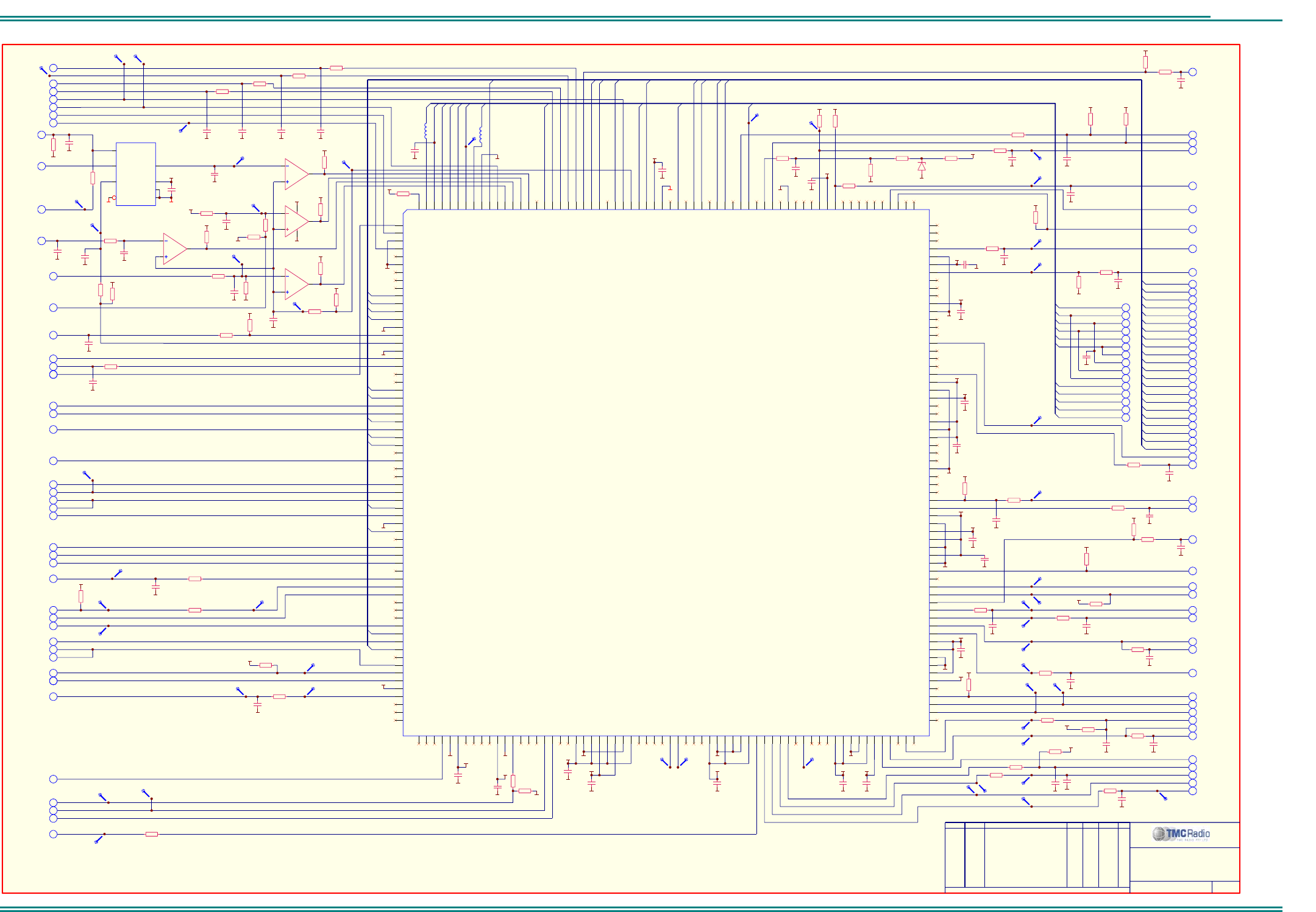
SRM9000X8 800MHz SERVICE MANUAL
© TMC Radio 2008 page 58 TNM-M-E-0022 Issue 1
TNM-M-E-0001
Sheet 3: PLA
Error : SIMOCO-1.WMF file not found.
ORDER DRAWN REMARKS EXAM APPD DATE REV
SRM9000 RADIO BOARD
6102 349 6232
3 of 12
ORDER DRAWN REMARKS
PROG LOGIC ARRAY
R326
1k0
8
9
14
U301C
LM239DR2G
0VA
0VA
0VA 0VA
6
7
1
U301B
LM239DR2G
0VA
3V3
3V3
R334
100K
3V3
0VA
BAT_SW
0VA
5V_D
BATTERY VOLTAGE
LOOP_VOLTS
EXT_SENSE1
C327
10n
R327
100K
R335
100K
R333
100K
R330
220K
3V3
R331
1k0
C326
N.F.
5
PA_ON 9
R336
10k
PWR_SENSE
C332
10n
0VA
9
R318
10k
TX_PWR
PWR_OFF
0VA
C333
10n
R329
4k7
3V3
R325
47k
R313
10k
C312
100n
R310
10k
C309
100n
0VA
R307
N.F.
C306
N.F.
MF25
0VA
MF2
MF3
MF4
R305
10k
MF5
C304
100n
MF6
0VA
MF7
MF24
RF_GAIN
0VA
DA_1
R311
10k
TUNE_2
C310
100n
TUNE_1
0VA
0VA
R304
N.F.
C305
100n
0VA
IF_GAIN
R312
10k
C311
100n 0VA
R306
10k
0VA
AFC
STBY
MOD_SW
5V_D
DONE
6
10
4
7
8
9
2
4
8
4
4
TX_MODE 8
3V3
2V5
0VA
0VA
2V5
3V3
5
0VA
2V5
3V3
0VA
2V5
3V3
RX_DATA2
10
GSEL
2
LB_RESET
2
0VA
R316
10k
C318
10n
0VA
/RD
R317
10k
2
C320
10n
0VA
3V3
2V5 0VA
3V3
0VA
2V5
0VA
C337
100n 0VA
C336
100n
0VA
C338
100n
0VA
C339
100n
0VA
C329
100n
0VA
C331
100n
0VA
C330
100n
0VA
C316
100n
0VA
C314
100n
0VA
C315
100n
0VA
C302
100n
0VA
2
2
2
2
2
2
2
2
2
2
2
2
2
/WR
CLKOUT
2
CLK_SHIFT
2
TA_/REP 6
LOCK 7
CSC_0
SCLK0
2
IRQ8
SINT
SOFS
/RESET
2
2
2
GCLK
2
GDAT
2
NCONFIG 2
L3D
L3C
C0FL
CLRC
CCLK
10
10
10
10
10
10
10
MF17
10
10
3V32V5
0VA
3V3
0VA
C340
100n
0VA
C341
100n0VA
C342
100n
0VA
10
2V5
C300
10n
0VA
3V3
C301
10n 0VA
0VA
0VA
0VA
3V3
L300
FB
R339
220K
R340
10k
5V_D
C328
1n0
MF25
MF2
MF3
MF4
MF5
MF6
MF7
MF24
10
10
10
10
10
10
10
0VA
C324
10n
10
7
C343
10n
0VA
R300
1k0
3V3
R301
10k
3V3
PTT_IN1
C323
10n
0VA
SPKR_ON 8
0VA
2
5V_D
R344
N.F.
0VA
ANALOG_IN
5V_A
R345
100K
0VA
5V_D
DATA_EN
C344
100n
8
R332
1k5
0VA
Y1b
1
Y0b
2
Zb 15
Sb
10 Vdd 16
Vee 7
Vss 8
6
U302A
MAX4053ACSE
BAT_SENSE
2
A4
A3
A2
A1
A0
A4
A3
A2
A1
A0
MF10
10
IGN_SENSE
2
R350
10k
0VA
C317
10n
0VA
D15
D14
D13
D12
D11
D10
D9
D8
D8
D9
D10
D11
D12
D13
D14
D15
MF10
0VA
10
TX_DATA2
10
0VA
R320
10k
C322
1n0
R349
10k
C347
1n0
0VA
10
10
8
TCK
10
TDI
10
TDO
10
TMS
TRST
MOD_BAL
0VA
7
10
10
0VA
9
0VA
0VA
C349
10n
R351
10k
PTT_IN2
TP302 TP305
5V_D
5V_D
R354
100K
R355
100K
5V_D
R356
100K
8
8
10
8
8
8
10
10
10
CCLK
L3C
CLRC
10
L3D
10
10
10
CSC_0
CCLK
L3D
CLRC
TRST
MF9
TMS
MF17
L3C
0VA
0VA
3V3
R363
N.F.
L3M_A 8
R324
N.F.
ALIGN_SEL
C308
100n
TP310
TP352
TP354
TP355
TP356
TP358
TP373
TP348
TP346
TP345
TP316
TP311
TP313
TP331
TP349
TP371
TP372
TP367
TP347
TP344
TP320
TP304
TP303
TP370
C325
10n
TP306 TP307
TP330
TP360
TP359
TP351
TP350
TP328
TP366
TP327
TP301
TP364
TP308
TP342
TP341
4
5
2
312
U301A
LM239DR2G
10
11
13
U301D
LM239DR2G
VCO_BIAS
5
R343
10k
L3M_B
OPTION ON/OFF
MF9
MF11
MF12
MF13
MF14
MF15
MF16
MF18
MF19
MF20
MF21
MF23
TP368
RX_DATA1
10
TX_DATA1
10
R341
47k
3V3
0VA
R346
220K
/RESET
10
OUTPUT0
VCAP_ADJ
R328
8K2
C321
N.F.
C319
N.F.
0VA
R353
100R
0VA
C313
10n
TP309
TP314
R358
100K
5V_D
R359
100K
5V_D
R323
2k2
C346
100n
R303
220R
R315
N.F.
R352
1k0
R360
680K
5V_TX
10
MF8
MF8
L301
FB
2
SCLK1
TFS
2
10 TFS
C352
10n
6
R321
1k0
0VA
C353
10n
CURRENT_SENSE
R308
2k2
C307
100n
R309
3k3
C348
10n
0VA
C303
100n
All Rights Reserved
1270 Ferntree Gully Rd Scoresby Australia 3179
C 2006 TMC Radio Pty Ltd ACN 099 952 977
O
AUDIO_EN2 8
AUDIO_EN4 8
RAMP
MF13
10 PF6
CURRENT_CAL
0VA
C334
100n
10
L3M_B
0VA
5
R319
1k0
R302
1k0
R364
1k5
R342
100K
R314
10k
R357
680K
AUDIO_EN3
3
R347
100K
5V_D
TP362
TP361 TP363
8
8
AUDIO_EN1
AF_GAIN
R361
100K
5V_D
R362
100K
5V_D
R322
1k0
0VA
13V8_UNSW_F
R365
680K
R366
470K
D301
BZX84-C5V6
0VA
R367
10k
PWR_STATUS
A1
A2
A3
A4
A5
A6
A7
A8
A9
A10
A11
A12
A13
A14
A15
A16
B1
B2
B3
B4
B5
B6
B7
B8
B9
B10
B11
B12
B13
B14
B15
B16
C1
C2
C3
C4
C5
C6
C7
C8
C9
C10
C11
C12
C13
C14
C15
C16
D1
D2
D3
D4
D5
D6
D7
D8
D9
D10
D11
D12
D13
D14
D15
D16
E1
E2
E3
E4
E5
E6
E7
E8
E9
E10
E11
E12
E13
E14
E15
E16
F1
F2
F3
F4
F5
F6
F7
F8
F9
F10
F11
F12
F13
F14
F15
F16
G1
G2
G3
G4
G5
G6
G7
G8
G9
G10
G11
G12
G13
G14
G15
G16
H1
H2
H3
H4
H5
H6
H7
H8
H9
H10
H11
H12
H13
H14
H15
H16
J1
J2
J3
J4
J5
J6
J7
J8
J9
J10
J11
J12
J13
J14
J15
J16
K1
K2
K3
K4
K5
K6
K7
K8
K9
K10
K11
K12
K13
K14
K15
K16
L1
L2
L3
L4
L5
L6
L7
L8
L9
L10
L11
L12
L13
L14
L15
L16
M1
M2
M3
M4
M5
M6
M7
M8
M9
M10
M11
M12
M13
M14
M15
M16
N1
N2
N3
N4
N5
N6
N7
N8
N9
N10
N11
N12
N13
N14
N15
N16
P1
P2
P3
P4
P5
P6
P7
P8
P9
P10
P11
P12
P13
P14
P15
P16
R1
R2
R3
R4
R5
R6
R7
R8
R9
R10
R11
R12
R13
R14
R15
R16
T1
T2
T3
T4
T5
T6
T7
T8
T9
T10
T11
T12
T13
T14
T15
T16
U300
SRMSRP10
C351
10u
.A09.10.06
..CM .. .INITIAL REALEASEU057
R348
10k
R370
10k
C335
100n 0VA
AFC_SW
5V_D
7
R369
N.F.
.B06.02.07
..CM .. .UPDATED TO REV BU089
ALC_SET
6
0VA
C345
100n
R337
10k
TP343
TP300
.C21.06.07
..CM .. .UPDATED TO REV CU128
30.72MHz
30.72MHz
0VA
C350
N.F.
0VA
C354
N.F.
.D07.12.07
..CM .. .UPDATED TO REV 2U167
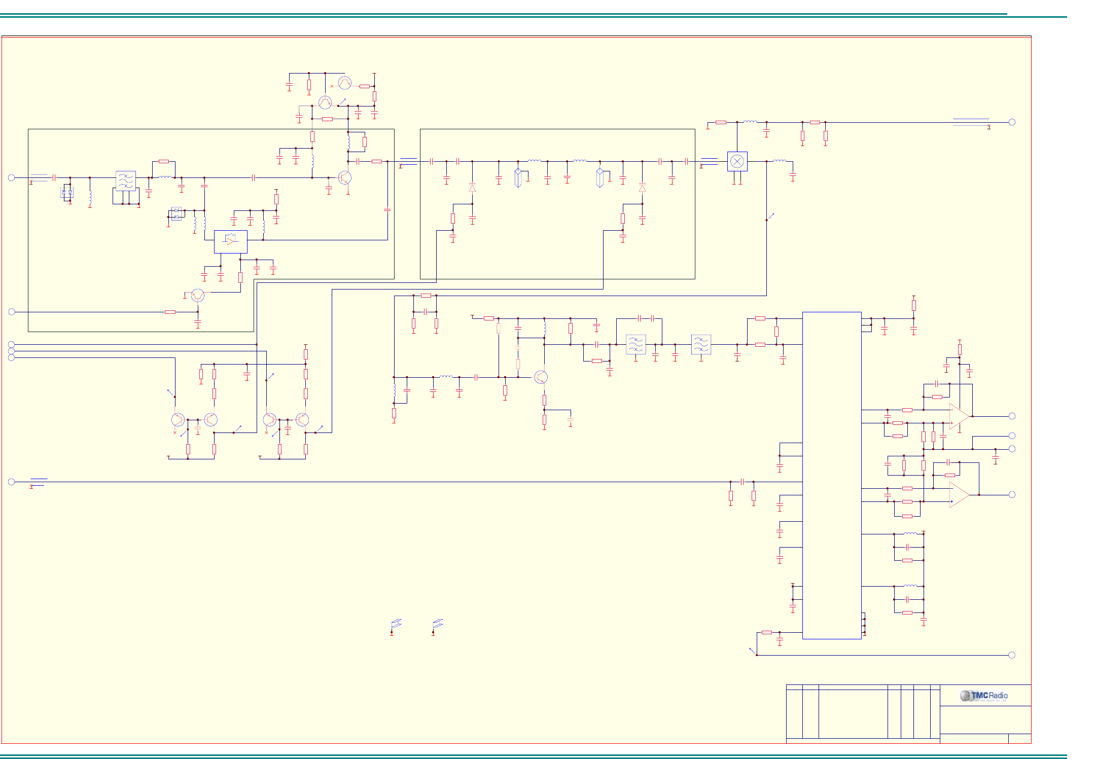
SRM9000X8 800MHz SERVICE MANUAL
© TMC Radio 2008 page 59 TNM-M-E-0022 Issue 1
TNM-M-E-0001
Sheet 4: Receiver
ORDER DRAWN REMARKS EXAM APPD DATE REV
All Rights Reserved
1270 Ferntree Gully Rd Scoresby Australia 3179
O
6102 349 6232
RECEIVER
4 of 12
R465
47R
Q461
BFR93AW
R469
4k7
R467
10k
C465
10n
C467
10n
L463
820n
R468
3k3
C464
10p
L462
820n
C461
27p
C462
10p
RX_LO1
R473
1k2
C469
10n
0VA
C474
12p
5V_RX
1st I.F. FILTER
IQ DEMODULATOR
E401
SHIELD
E402
SHIELD
0VA 0VA
C476
1n0
L491
1u0
C482
1n0
0VA
0VA
C483
1n0
0VA
C496
10p
L492
1u0
C497
10p
3Q3
C498
10n
0VA
0VA
C480
1n0
0VA
3Q3
0VA
3Q3
C484
10n
0VA
C485
10n
0VA
0VA
R466
47R
0VA
3
6
0VA
R483
33K
0VA
I_CH
Q_CH
C486
10n
R477
1k0
R498
470R
R499
470R
8
8
C473
1p5
IF_GAIN
R484
10R
5
0VA
RX_IN
C463
10p
C471
1p5
C472
1p5
R472
100R
R471
33R
C468
N.F.
R474
470R
TP460
Vcc1 1
Vcc2 2
Vcc3 3
CDMA IN+
4
CDMA IN-
5
GND 6
GND 7
FM IN+
8
FM IN-
9
BG OUT
10
DEC
11
LO-
12
LO+
13
IN SEL
14
Q OUT- 15
Q OUT+ 16
GND 17
FL- 18
FL+ 19
GND 20
I OUT+ 21
I OUT- 22
GC
23
PD
24
U481
RF9957A
12
3
Z471A
45T122CF
12
3
Z471B
45T122CF
2
3
1
84
U491A
LMV358M/NOPB
6
5
7
U491B
LMV358M/NOPB
0VA
8
5V_A
0VA
1V65
C489
100n
R485
1k0
0VA
R486
220K
R487
220K
R488
220K
R494
220K
R495
220K
R496
220K
R493
220K
R490
220K
C470
N.F.
C475
N.F.
R475
0R
R476
3k3
C460
82p
C495
4n7
C491
4n7
C490
47p
C494
47p
7
L461
180n
R489
N.F.
R497
N.F.
R492
N.F.
R491
N.F.
C492
47p
C493
47p
Z430
970MHz
L431
8n2
L432
8n2
C431
5p6
C436
12p
C430
22p
C432
4p7
C441
3p9
C440
3p3
C443
22p
0VA 0VA 0VA
0VA 0VA
0VA
C435
0p6
0VA
C437
N.F.
0VA
R422
4k7
C433
1n0
0VA
R412
220R
R409
1k0
R407
47R
5V_RX
R421
0R
C406
47p
0VA
C404
N.F.
C417
100n
L406
3n3
0VA
C403
3p3
0VA
C424
10p
C401
100p
L405
3n3
0VA
0VA 0VA
R406
2k2
R405
12k
C418
100n
0VA
R404
N.F.
5V_RX
C426
N.F.
L407
N.F.
L408
N.F.
In
3
Gnd
1
Out 2
Gnd
4
U401
N.F.
0VA
C411
N.F.
0VA
0VA
C414
N.F.
0VA
0VA
C408
N.F.
0VA
0VA
0VA
0VA
0VA0VA
C439
4p7
0VA
R423
4k7
C438
1n0
0VA
R454
220K
R453
47k
R450
680K
-12V
3
R459
220K
R458
47k
R455
680K
-12V
3TUNE_2
TUNE_1
TP410
TP414
R451
10k
R456
1k0
0VA 0VA
3P3
R452
4k7
R457
4k7
TP412
TP411 TP415
TP416
Q452
BC859CW
Q451
BC859CW
Q454
BC859CW
Q453
BC859CW
C450
N.F.
0VA
C452
N.F.
0VA
Q401
N.F.
0VA
R403
N.F.
0VA
C415
N.F.
RF_GAIN
3
0VA
R427
10R
R426
470R
R428
470R
0VA 0VA
L449
10n
C447
10p
0VA
R408
N.F.
0VA
RX_LO2
0VA
7
0VA
Q404
BFR380F
D401
N.F.
R480
N.F.
R482
N.F.
0VA 0VA
RF AMP (WITH BYPASS)
RF AMP (FIXED GAIN)
TUNED FILTER
MIXER
IF AMPLIFIER
SAW FILTER
R462
N.F.
R461
N.F.
R463
N.F.
0VA 0VA
D431
1SV229
D432
1SV229
45
1
2
3
LO
RF
GND GND
IF
U441
MAMXSS0012
Q403
BC859CW
Q402
BC859CW
0VA
R402
N.F.
0VA0VA0VA0VA
0VA
0VA
0VA
0VA
0VA
0VA
C479
1u0
C445
3p9
L448
22n
C 2006 TMC Radio Pty Ltd ACN 099 952 977
C481
N.F.
R414
N.F.
L402
3n3
C400
N.F.
0VA
C410
1u0
0VA
C451
10u
C499
12p
0VA
C487
10n
0VA
Z431
970MHz
C434
4p7
0VA
C488
N.F.
.A09.10.06
..CM .. .INITIAL REALEASEU057
SRM9000 RADIO BOARD
C412
N.F.
C413
N.F.
C422
100p
C409
N.F.
C421
100p
C419
10n
C405
N.F.
R424
820R
SHIELD E401
SHIELD E402
(-7.5dBm)(-8dBm)
L409
N.F.
0VA
C466
1n0
.B06.02.07
..CM .. .UPDATED TO REV BU089
0VA 0VA
0VA
L401
6n8
0VA
C402 deleted
C407
3p3
43
16
D402
MBD330DWT1G
2
6
4
3
5
1
Z400
860.5MHz
FILTER SAW
TP441
TP408
6TUNE_1N
.C21.06.07
..CM .. .UPDATED TO REV CU128
C459
150p
.D07.12.07
..CM .. .UPDATED TO REV 2U167
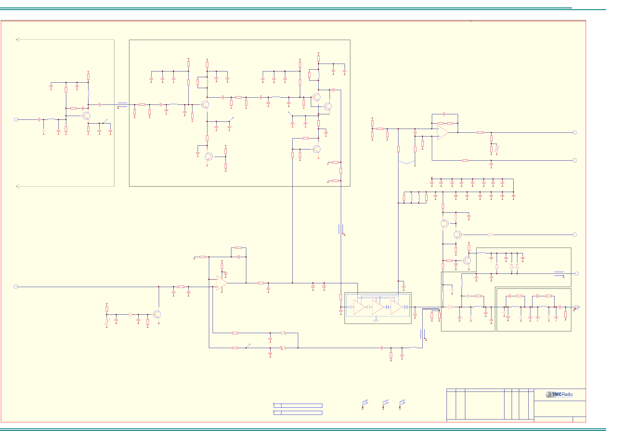
SRM9000X8 800MHz SERVICE MANUAL
© TMC Radio 2008 page 60 TNM-M-E-0022 Issue 1
TNM-M-E-0001
Sheet 5: Transmitter
ORDER DRAWN REMARKS EXAM APPD DATE REV
E502
SHIELD
E501
SHIELD
0VA 0VA
E506
SHIELD COVER
E505
SHIELD TRAY
All Rights Reserved
1270 Ferntree Gully Rd Scoresby Australia 3179
C 2006 TMC Radio Pty Ltd ACN 099 952 977
O
0VA
6102 349 6232
TRANSMITTER
5 of 12
D581
MA4P1250
0VA
4
L573
47n
0VA
L592
7n
L593
7n
L594
7n
R591
47k
L591
7n 0VA
0VA 0VA 0VA 0VA 0VA
R573
15R
Q571
BCX51
Q572
BC849CW
R575
150R
R579
4k7
C589
2p7
C592
1p0
C595
2p7
C598
2p7
C590
1p0
Q573
PMMT491A
0VA
13V8_UNSW
R577
2k2 0VA 0VA
C593
1p0
RX_IN
C581
1n0
0VA
C596
1p0
50_8
C599
47p
0VA
S501
0VA
50_2
PA_ON
R574
22R
3
R578
4k7
C582
N.F. 0VA
D582
BAR88-02V
D583
BAR88-02V
C587
10n
R567
0R
0VA
C563
N.F.
0VA
L571
FB
C566
22n
0VA
C574
1n0
0VA0VA
13V8_UNSW
2
3
1
84
U551A
LMV358M/NOPB
0VA
0VA
5V_TX
C555
10n
R562
39k
0VA
TX_PWR
L561
15n
R568
N.F.
C569
1p8
R569
470R
C568
1n0
13
D561A
BAS70-04W
32
D561B
BAS70-04W
C557
1n0
0VA
0VA
0VA 0VA
0VA
R559
2k2
0VA
6
5
7
U551B
LMV358M/NOPB
C571c
100n
C552
1n0
0VA
0VA
0VA
(16dBm) (45dBm)
0VA0VA
0VA0VA0VA 0VA0VA0VA 0VA
C579b
1n0
C579a
100p
C578c
10n
C571b
1n0
C571a
100p
C579c
10n
C578b
1n0
C578a
100p
C577
10n
0VA
+
C573
10u
0VA
C567
N.F.
0VA
13
D551A
BAV99W
R556
100K
R558
100K
Q551
BC849CW
0VA
0VA
5V_TX
R563
10R
R572
N.F.
R571
N.F.
R565
0R
C554
100n
C553
100n
C551
100n
C550
N.F.
0VA
C541
1n0
0VA
-t
R554
100k
C556
10n
0VA
R561
10k
R544
100K
R546
100K
0VA
R564
10R
L572
FB
C562
10n
C565
N.F.
R547
33K
R548
680K
BATT_IN
16mohms
R566
39k
4k7 @ t = 85°C
R549
680K
3
0VA
R542
180K
R540
68K
R541
47k
5V_TX
U
R557
470R
R545
180K
3
0VA
R543
33K
CURRENT_CAL
CURRENT_SENSE 3
0VA
C542
N.F.
POWER AMPLIFIER MODULE
HARMONIC FILTER
R551
68k
R552
220K
R553
39k
0VA
C560
1u0
C584
10p
C583
12p
0VA
C588
2p7
C585
3p9
0VA
C586
N.F.
R576
100K
L581
47n
0VA
+
C572
N.F.
C575
1u0
C576
1u0
0VA
0VA
C543
N.F.
0VA
Q531
N.F.
0VA
0VA
0VA
0VA
0VA
C532
10n
0VA
C539
4p7
R536
270R
R538
270R
R537
22R
Q532
BC849CW
8V_RF
0VA
0VA
R534
10R
0VA
C531
100p
0VA
0VA
0VA
C538
100p
0VA
R532
10k
C533
N.F.
L531
10n
R530
1k8
R533
10k
0VA
C534
10n
R531
22K
C536
10u
6TX_RF
5V_TX
R501
1k0
R503
N.F.
C504
N.F.
C503
100p
C511
4p7
0VA 0VA 0VA 0VA0VA
0VA
TX BUFFER
C506
10n
0VA
5V_TX
R504
10R
R511
120R
R513
120R
R512
68R
0VA 0VA
(5dBm)
L501
8n2
0VA
0VA
0VA
0VA
0VA 0VA
C523
4p7
R525
150R
R527
150R
R526
47R
Q522
BC849CW
0VA
0VA 0VA
R523
2k2
L502
10n
C514
4p7
C512
47p
C517
N.F.
R524
10k
0VA
C524
10n
R522
82R
C518
10u
8V_RF
R521
10R
0VA
0VA
C522
100p
C516
10n
0VA0VA
C515
100p
0VA
R515
1k2
5V_TX
Q521
BFR380F
Q501
BFR380F
5V_TX
TX DRIVER AMPLIFIER
TX PRE-DRIVER AMPLIFIER
C526
47p
R505
68R
R514
10R
R528
10R
C513
1u0
C530
1u0
(1dBm)
(10dBm)
(10dB)
(7dB)
(4dB)
(20dBm)
(17dBm)
R502
1k0
C501
47p
POWER CONTROL
THERMAL SHUT-BACK
MAX CURRENT LIMITER
RF DETECTOR
ANTENNA SWITCH
1
2
3
4
U561
RA45H8087M-101
0VA
0VA
C598a
N.F.
0VA
C595a
N.F.
0VA
C592a
N.F.
0VA
C592b
N.F.
R539
N.F.
0VA
C595b
N.F.
R520
N.F.
C527
4p7
L522
10n
0VA
C592c
N.F.
Q531a
BFR380F
C502
4p7
L511
8n2
L521
10n
R529
1k2
R516
1k5
R535
68R
.A09.10.06
..CM .. .INITIAL REALEASEU057
SRM9000 RADIO BOARD
C507
N.F.
R592
0R
R593
0R
R594
0R
C535
100p
C537
10n
C521
10n
C508
10n
C509
100p
C525
100p
MAY NEED TO CHANGE TO TANTALUM!
SHIELD E503
SHIELD E502
SHIELD E501
TRAY E505
COVER E506
P/O SHIELD E603
E503
SHIELD
(8dBm)(15dBm)
(-1dBm)
(CH0: 0.8dBm)
(CH1: 0.6dBm)
(CH2: 1.9dBm)
(CH3: 1.6dBm)
(CH0: 15.9dBm)
(CH1: 15.8dBm)
(CH2: 15.4dBm)
(CH3: 14.5dBm)
R560
100R
0VA
.B06.02.07
..CM .. .UPDATED TO REV BU089
0VA
0VA
0VA
0VA
D580
N.F.
C580
N.F.
TP561
TP531
TP521
TP501
.C21.06.07
..CM .. .UPDATED TO REV CU128
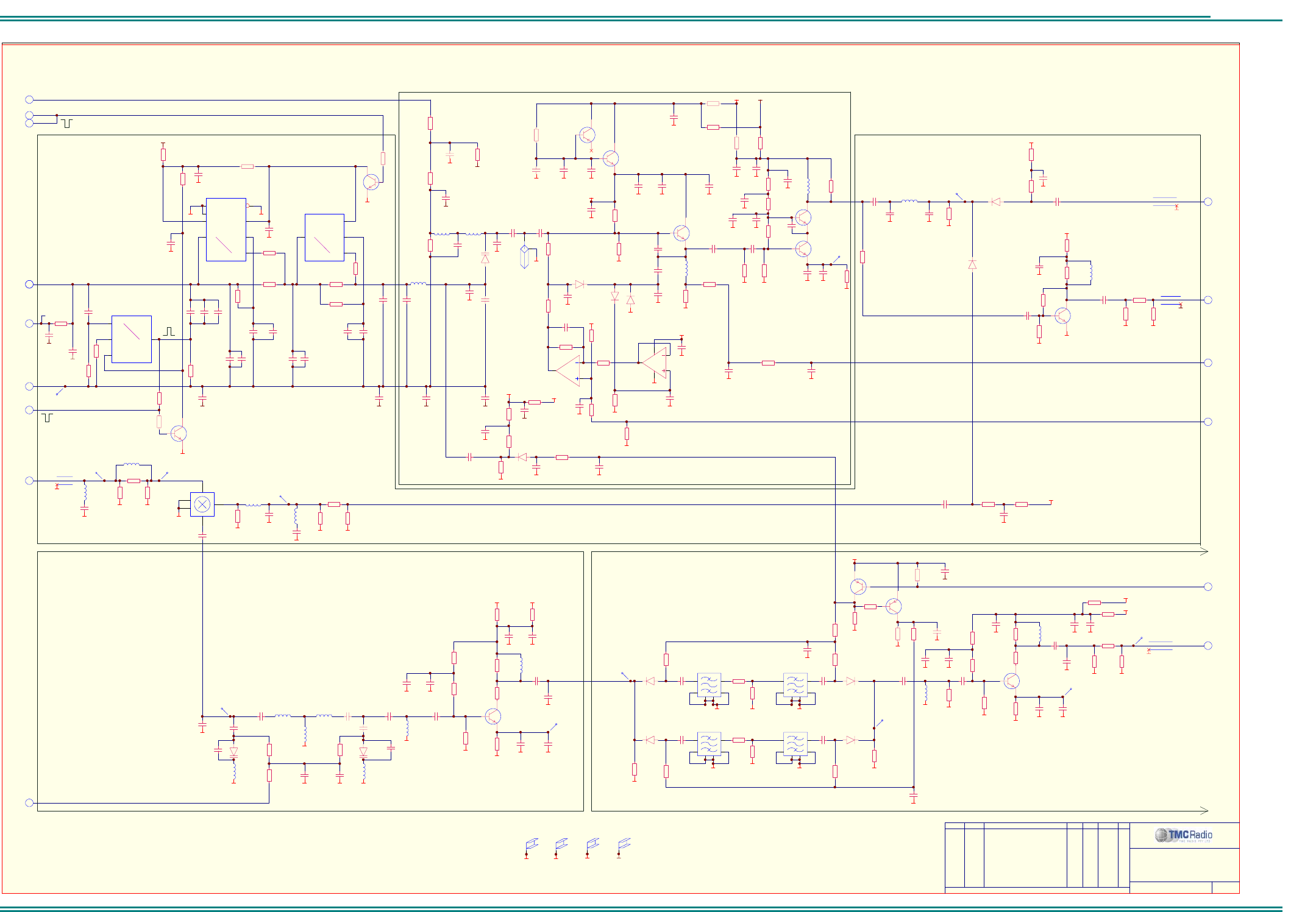
SRM9000X8 800MHz SERVICE MANUAL
© TMC Radio 2008 page 61 TNM-M-E-0022 Issue 1
TNM-M-E-0001
Sheet 6: VCO
ORDER DRAWN REMARKS EXAM APPD DATE REV
C611
N.F.
L601
100n
C624
10p
C625
2p2
L624
18n
R632
100R
C640
2p7
C639
5p6
R643
2k2
R639
3k3
R645
2k2
C647
27p
C646
10p
C645
10n
C632
100n
C628
10n
R638
1k0
0VA
0VA
0VA
0VA 0VA
0VA 0VA 0VA
0VA
0VA
0VA
R627
N.F.
C633
10u
C644
10u
Q622
BC849CW
R624
1k0
R625
10R
R626
N.F.
5V_RFF
PRIMARY VCO
R629a
N.F.
0VA 0VA 0VA
R635
220R
R636
4k7
R644
100R
0VA
0VA
D641
BAR88-02V
D642
BAR88-02V
C653
10n
5V_RX
C654
100p
0VA
C657
10p
R650
N.F.
R649
100K
0VA
0VA
L642
12n
R642
680R
C659
1n0
R648
270R
R647
1k2
C656
1n0
0VA
5V_RFF
Z620
1250MHz
0VA
0VA
C629
47p 0VA
D610
1SV229
C614
N.F.
C641
2p2
0VA
0VA
R628
10k
R640
560R
R641
82R
0VA
C649
100p
L623
100n
R618
N.F.
R620
N.F.
R619
N.F.
0VA
C620
N.F.
C619
N.F.
R617
N.F.
C618
N.F.
0VA
5V_RFF
D624
N.F.
0VA
0VA0VA
R652
N.F.
R654
N.F.
0VA 0VA
Q623
BFR380F
Q631
BFR380F
Q632
BFR380F
Q640
BFR380F
L621
100n
L652
27n
D660
1SV229
L661
8n2
C661
100p
C667a
N.F.
R666
100K
C662
2p2
C667
2p2
0VA
0VA
0VA
0VA
0VA
0VA
0VA
0VA 0VA
0VA
R665
10k
C694
10u
R678
0R
TX MIXER
R659
820R 0VA
R676
4k7
0VA
0VA
0VA
0VA
0VA
D684
BAR88-02V
D682
BAR88-02V
C688
10n
0VA
0VA
45
1
2
3
LO
RF
GND GND
IF
U650
MAMXSS0012
2
6
4
3
5
1
Z681
815.5MHz
L662
8n2
D661
1SV229
C670
3p3
C672
2p2
0VA
R664
100K
L663
3n3
D683
BAR88-02V
D681
BAR88-02V
2
6
4
3
5
1
Z683
815.5MHz
2
6
4
3
5
1
Z684
860.5MHz
R680
0R
R679
2k2
R681
2k2
860.50MHz
815.50MHz
BUFFER
C668
N.F.
C673
N.F.
C683
100p
C684
15p
C686
100p
C687
15p
C697
3p3
L692
12n
R696
56R
C691
100p
0VA 0VA
R690
1k0
R692
2k2
R691
4k7
R695
0R
0VA
0VA
C692
10n
0VA
0VA
C698
N.F.
R694
N.F.
R693
N.F.
0VA
C696
10n
0VA
0VA
C680
100p
L672
N.F.
R674
56R
C675
100p
0VA 0VA
R668
1k0
R670
2k2
R669
4k7
R673
10R
0VA
0VA
C676
10n
0VA
0VA
C681
N.F.
R672
100R
R671
N.F.
0VA
C679
10n
0VA
5V_RF
R698
22R
R697
270R
R699
270R
0VA 0VA
R657
33R
R658
150R
0VA 0VA
Q670
BFR380F
Q691
BFR380F
L650
N.F.
C660
N.F.
0VA
L653
N.F.
C663
N.F.
0VA
L651
N.F.
L664
8n2
L665
8n2
4TUNE_1N
TX_LO2
0VA
7
FIN_RF 7
RX_LO1 4
0VA
TX_MOD2
7
TX_RF 5
0VA
6102 349 6232
PRIMARY VCO
6 of 12
TUNED FILTER SWITCHED SAW FILTERS
BUFFER
2
6
4
3
5
1
Z682
860.5MHz
VCAP_BIAS
3
LOOP_VOLTS
C601
100p
C615
100p
0VA
R601
680K
7
7FAST
LOOP FILTER
0VA
7
R612
6k8
CPP_RF
C602
N.F.
C606
N.F.
Y1a 13
Y0a 12
Za
14
Sa 11
U601C
MAX4053ACSE
Y1c
3
Y0c
5
Zc 4
Sc
9
U601B
MAX4053ACSE
0VA
0VA
R615
N.F.
0VA
R614
0R
Y1b 1
Y0b 2
Zb
15
Sb 10
Vdd
16 Vee
7Vss
86
U601A
MAX4053ACSE
16V
0VA
0VA
C610
N.F.
C608
N.F.
C634
100p
0VA
0VA
Q621
BC859CW
+
C626
47u
C623
470p 0VA
R621
100K
C638
10n
R605
680K
R604
100R
C604a
1n0
C603
1n0
C685
10n
0VA
C689
10n
0VA
5V_RF
Q601
BC849CW
R616
100K
C600
1n0
3
C616
100p
0VA
C617
100p
0VA
TA_/REP
C665
10n 0VA
R600
2k2
C664
100p
R610
100R
5V_TX
All Rights Reserved
1270 Ferntree Gully Rd Scoresby Australia 3179
C 2006 TMC Radio Pty Ltd ACN 099 952 977
O
0VA
C613
8p2
E600
SHIELD
0VA
E601
SHIELD
0VA
C666
3p3 0VA
0VA
TP682
TP681
TP661
TP653
TP652
TP651
TP601
TP692
R675
12k
R686
12k
R677
12k
R685
12k
R687
4k7
R653
33R
R688
100R
R684
100R
.A09.10.06
..CM .. .INITIAL REALEASEU057
SRM9000 RADIO BOARD
C606a
N.F.
C605
470n
C607a
22n
C607
22n
C609
N.F.
C609a
8n2
C608a
N.F.
C610a
N.F.
R602
1k0
R603
N.F.
R609
3k3
R611
N.F.
R613
N.F.
R606
N.F.
R607
N.F.
C612
33p
C678
100p
C682
27p
C682a
N.F.
C674
100p
C669
100p
C671
10n
C699
47p
C699a
N.F.
C695
100p
C690
100p
C627
100p
C631
100p
C630
10n
C644a
100p
-0.4V
Q682
BC859CW
R682
10k
R683b
4k7
0VA
C650
100p
0VA
2.25V
1.5V
NOTE: These values give approx 5ms/15ms lock-time for ±500Hz.
FracN Settings = 5.0ms/1500uA/85uA
(-12dBm)
(-7dBm)
(-9dBm)
(0dBm)
SHIELD E602
SHIELD E601
SHIELD E600
(3dBm)
(0dBm)
(-6dBm)(-1dBm)
(-2dBm)
(-9dBm)
(1.4dBm)
(3.7dBm)(2.5dBm)
(3dBm) (3.5dBm)
(8dBm)
Q681
BC859CW
0VA
5V_RF
R683
100K
(CH0: 5.7dBm)
(CH1: 4.8dBm)
(CH2: 3.9dBm)
(CH3: 3.8dBm)
C651
100p
0VA
C648
100p
0VA
R637
100R
C647a
27p
0VA
L641
12n
R683a
4k7
8V_RF
R626a
330R
R625a
N.F.
TA
/REP
/TA_REP
0VA
E603
SHIELD
E602
SHIELD
0VA
SHIELD E603
0VA
L670
8n2
0VA
L691
10n
C693
3p3
5V_TX 5V_TX
R671a
22R
R693a
22R
0VA
Q602
BC849CW
R616a
100K
R605a
680K
0VA
C604
1n0
PLL_STB
2
6
R689
220R
0VA
(2dB)
C642a
N.F. 0VA
.B06.02.07
..CM .. .UPDATED TO REV BU089
0VA
C642
N.F. 0VA
C677
3p3
2
3
1
84
U620A
LMV358M/NOPB
6
5
7
U620B
LMV358M/NOPB
D621
N.F.
D623
BAT62-02W
D622
BAT62-02W
R623
100R
R634
10k
R630
82K
R631
15k
R629
18k
4V_VCO
4V_VCO
4V_VCO
0VA
0VA
C636
330p
C638a
N.F.
0VA
C636a
100n
R646
680K
0VA ALC_SET 3
R655
N.F.
0VA
VCO_BIAS 3
R633
10k
C637
100n
0VA
R651
10k
C655
100n
0VA
PA timing = 7.0ms
TP691
TP680
TP631
TP650
0VA
C635
10n
C651a
N.F.
R608
680R
R622
82K
C621
100p
0VA
0VA
C622
1p5
R621a
47k
C658
100p
0VA
0VA
C658a
100p
.C21.06.07
..CM .. .UPDATED TO REV CU128
5V_RF
R667
1R
L622
100n
C621a
10n
R662
10R
R661
470R
R663
470R
C643
1p5
C619a
N.F.
0VA
R656
150R
.D07.12.07
..CM .. .UPDATED TO REV 2U167
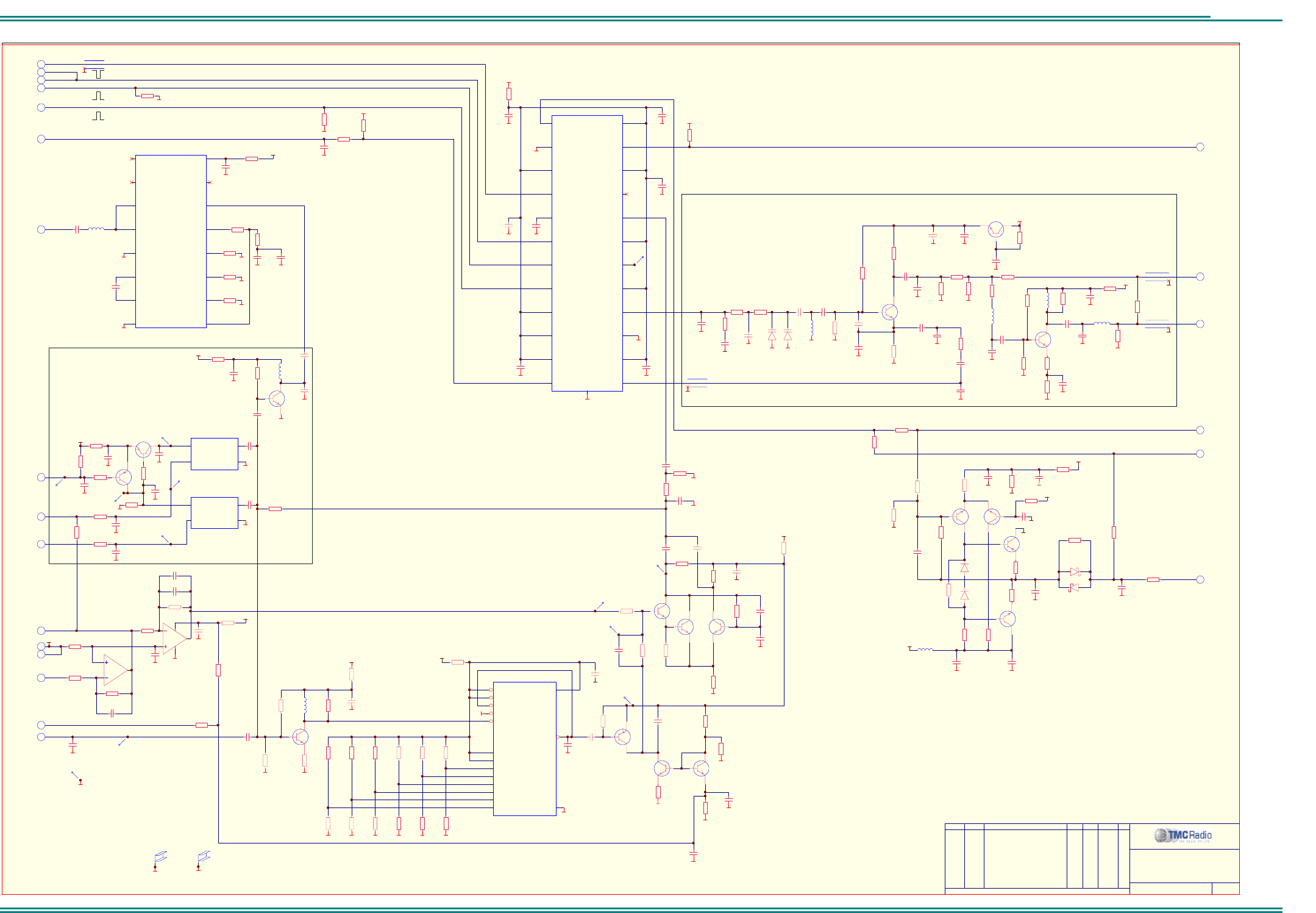
SRM9000X8 800MHz SERVICE MANUAL
© TMC Radio 2008 page 62 TNM-M-E-0022 Issue 1
TNM-M-E-0001
Sheet 7: Synthesiser
ORDER DRAWN REMARKS EXAM APPD DATE REV
All Rights Reserved
1270 Ferntree Gully Rd Scoresby Australia 3179
C 2006 TMC Radio Pty Ltd ACN 099 952 977
O
6102 349 6232
SYNTHESIZER
7 of 12
5V_RFF
0VA
0VA
R712
10k
REFERENCE OSCILLATORS
R715
10R
R703
47k
C701
10n
R702
1k0
0VA
R730
10R
3P3
6
2
2
2
FIN_RF
CPP_RF
3
PLL_CLK
PLL_DATA
PLL_STB
LOCK
0VA
0VA
0VA
C764
N.F.
3AFC
R701
10k
0VA
R700
10k
0VA
C717
47p
0VA
R707
47R
C729
N.F.
C747
10n
C728
10n
3
VCAP_ADJ
R714
N.F.
MOD_BAL
3
TX_MOD1
VCAP_BIAS 6
8
TP711
TP712
R716
2k2
R717
5K6
C732
100n
0VA
C718
100n
C733
1u0
TP743
TP744
0VA
EXT_REF
10
R745
100R
8
4
R713
N.F.
C715
22p 0VA
0VA
5V_RFF
2DSP_CLK
0VA
2REF_SHIFT
0VA
FINIF 13
FINRF-
5
CPRF
1
GND 15
VDDIF2 17
VDDIF1 14
CPIF 16
LE
6
REFOUT 18
REFEN 19
CE
10
FINRF+
4
REFIN 20
CLK
8
GND
2
VDDRF2
9
DATA
7
VDDRF1
3
FLRF 23
VDDRF4 24
VDDRF5
11
LD
12
VDDRF3 22
NC 21
GND
0
U721
LMX2485E* NOPB
0VA
0VA
0VA
0VA
C722
10n
FAST
3P3
C726
100n
0VA
C723
100n
0VA
R785
N.F.
SYNTHESIZER
C724
100n
0VA
C725
100n
0VA
C720
100n
0VA
0VA
R799
0R
R784
0R
ADJ
1
OUT 3
VCC
4
GND 2
U711
15.36MHZ
6
6
C740
1n0
Q730
BFR93AW
R721
18k
C742
10n
R725
1k5
0VA 0VA
C739
18p
C735
47p
C734
10n
D730
1SV229
L730
100n
0VA
C737
10n
0VA
R732
10k
0VA
R722
27k
Q731
BC849CW
90MHz LOCAL OSCILLATOR
R720
2k2
R724
220R
0VA
0VA
0VA
0VA0VA
D731
1SV229
5V_RFF
C744
100n
0VA
0VA
C738
N.F.
C741
N.F.
0VA
C754
1n0
0VA
R739
N.F.
0VA
R738
15R
C757
18p
R743
470R
L734
100n
C751
10n
0VA
L732
220n
0VA
R728
18R
R727
270R
0VA 0VA
5V_RFF
RX_LO2 4
0VA
TX_LO2 6
0VA
R742
N.F.
0VA
L751
10u
R753
N.F.
0VA 0VA
5V_RFF
0VA
1
2
3
4
5
6
7
10
11
12
13 8
14
16
9
15
MR
PL
PE
TE
CP
TC
P0
P7
P1
P2
P3
P4
P5
P6
VCC
GND
U760
74HC40103PW
0VA
0VA
R759f
N.F.
R758b
N.F.
R758a
N.F.
R758c
N.F.
0VA 0VA 0VA
0VA
0VA
0VA
0VA
0VA
REFERENCE OSC. MODULATOR
R759e
N.F.
R759d
N.F.
0VA 0VA 0VA
5V_A
0VA
0VA
2
3
1
84
U761A
LMV358M/NOPB
0VA
5V_RFF
0VA
DIVIDER (/32)
Q751
BC849CW
R758d
10k
R759c
10k
R759a
10k
R759b
10k
R758f
10k
R758e
10k
C766
10n
R754
3k3
R751
47k
R750
47k
R752
270R
R746
10R
R760
33R
C762
1u0
R748
680k
R762
47k
R767
47k
R768
2k2
C771
1u0
R770
100k
C770
27p
Q771
BC859CW
Q773
BC849CW
Q772
BC849CW
C778
150p
Q775
BFR93AW
Q774
BFR93AW
Q776
BFR93AW
C774
10n
R765
10R
C775
10u
6
5
7
U761B
LMV358M/NOPB
R778
8K2
R777
10k
0VA
5V_RFF
C779
N.F.
R769
470R
C777
N.F.
R764
2k2
R763
4k7
R766
100k
R771
820R
C776
4p7
TP745
TP746
TP747
TP748
C763
100n
C761
100n
C760
100n
R773
3k9
R775
8K2
R774
820R
0VA
R772
10k
R747
22K
C772
33p
R776
1k0
R798
N.F.
R795
10R
R796
10R
R792
100k
R791
100k
R788
100k
C780
1n0
Q782
BC859CW
Q783
BC849CW
C783
N.F.
5V_RFF
0VA
V.C.O. VARICAP POSITIVE SUPPLY
C781
10n
0VA 0VA
R797
47k
16V
C787
10n
0VA
13
D782A
BAT54SW
32
D782B
BAT54SW
0VA
0VA
L780
10u
0VA
0VA
1V65
C773
N.F.
R729
270R
C755
10n
R734
0R
R733
N.F.
R735
3k3
R740
47R
R736
3k3
R737
100R
C750
6p8
Q734
BFR380F
0VA
C758
10n
0VA
C745
22p
C746
100p
Q780
BC849CW
Q781
BC849CW
0VA
C784
10n
ADJ
1
OUT 3
VCC
4
GND 2
U712
15.36MHZ
Q700
BFR380F
C704
1n0
C705
100p
L703
1u0
R705
100K
R704
1k2
C706
10n
R709
10k
0VA
0VA
C748
N.F.
90MHz BUFFER
C713
10n
C788
1u0
C786
10u
C721
100n
R787
15k
R786
22K
R790
8K2
32
D780B
BAV99W
13
D780A
BAV99W
R789
N.F.
C714
47p
0VA
Q712
BC859CW
Q711
BC859CW
C712
N.F.
R708
10k
R711
47k
R710
4k7
0VA
C716
10n
TP713
TP714
C743
1u0
L733
470n
0VA
C769
100p
C782
N.F.
.A09.10.06
..CM .. .INITIAL REALEASEU057
SRM9000 RADIO BOARD
C765
N.F.
R793
N.F.
R783
0R 0VA
R794
10k
R719
2k2
R718
220R
(-8dBm)
(-18dBm)
(0.5dBm)
SHIELD E700
E700
SHIELD
0VA
(-7.5dBm)
(6.6dBm)
(-8dBm)
R731
10k
3P3
3V P-P
6
AFC_SW
3
0VA
R712a
10k
C719
100n
TP715
.B06.02.07
..CM .. .UPDATED TO REV BU089
0VA
0VA
.C21.06.07
..CM .. .UPDATED TO REV CU128
SHIELD E701
E701
SHIELD
0VA
0VA
C711
1u0
TX_MOD2
6
1V65
C767
1n0
R1 11
INH
5
PC1out
2PC3out 15
SIGin 14
VCC 16
C1a
6
DEMout 10
VCOout
4
GND
8
R2 12
PC2out 13
PCPout
1
COMPin
3
VCOin 9
C1b
7
U701
74HC4046APW
C702
6p8
L701
10u
R706c
22K
R706a
10k
R706b
470R
R706d
22K
R706
100R
R706e
N.F.
0VA
C707
22p
0VA
C708
1u0
0VA
C709
100n
0VA
0VA
0VA
0VA
5V_D
5V P-P
C709b
N.F.
0VA
C768
1u0
0VA
TP720
1.4~2.5VDC
3.6VDC
3.8V P-P
15.36MHz
15.36MHz
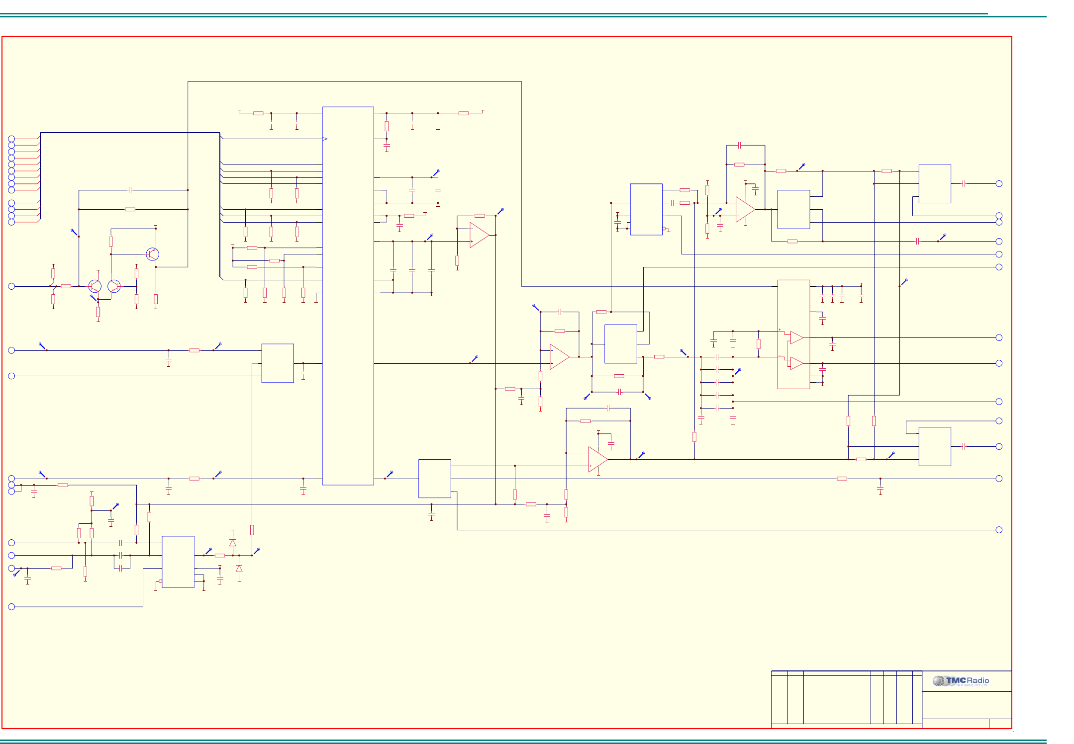
SRM9000X8 800MHz SERVICE MANUAL
© TMC Radio 2008 page 63 TNM-M-E-0022 Issue 1
TNM-M-E-0001
Sheet 8: TX/ RX Audio
ORDER DRAWN REMARKS EXAM APPD DATE REV
A
UDIO PRCCESSING
6102 349 6232
8 of 12
0VA
7
TX_MOD1
0VA
VssADC 1
VddADC 2
VINL
3
VrefADC 4
VINR
5
ADCref- 6
ADCref+ 7
TEST1
8
OVERFL
9
VddD
10
VssD
11
12
L3MODE
13
L3CLK
14
L3DAT
15
SCLK
16
LRC
17 TXD
18 RXD
19
TEST3
20
TEST2
21
VssDAC 22
VddDAC 23
VOUTR 24
VddAMP 25
VOUTL 26
VssAMP 27
VrefDAC 28
MCLK
U800
UDA1344TS
C813
100n
R825
10k
C814
100n
0VA
C816
100n
0VA
0VA
3C3
3C3
0VA
C807
100n
0VA
3V3
R816
10k
R815
10k
R814
10k
R819
10k
R818
10k
R817
10k
0VA
0VA0VA0VA
CCLK
CSC_0
CDI
CDO
CLRC
L3C
L3D
L3M_A
C0FL
+
C812
N.F.
C815
10u
0VA 0VA 0VA
Y1c 3
Y0c 5
Zc
4
Sc 9
U801B
74HC4053D
0VA
0VA
0VA0VA
I_CH
Q_CH
R824
1k8
4
4
5V_D
0VA
2
3
1
84
U802A
LMV358M/NOPB
0VA
AUDIO_OUT2
C825
100n
0VA
10
R861
10k
C866
47n
R863
22K
C873
1n0
R864
22K 0VA
13V8_UNSW_F
0VA 0VA
0VA
0VA0VA
1
9
4
6
RR 3
Vp 7
M/SS
8
Gnd1 2
Gnd2 5
U805
TDA1519B
Q810
BC849CW 13V8_UNSW_F
C831
100p
0VA
C832
100p
0VA
SPKR_OUT1
SPKR_OUT2
0VA
10
10
+
C829
N.F.
0VA
C842
10n
0VA
0VA
Y1a
13
Y0a
12
Za 14
Sa
11
U801C
74HC4053D
Y1b
1
Y0b
2
Zb 15
Sb
10 Vdd 16
Vee 7
Vss 8
6
U801A
74HC4053D
0VA
5V_A
0VA
2
3
1
84
U803A
LMV358M/NOPB
C854
100n
0VA
C852
1n0
0VA
6
5
7
U803B
LMV358M/NOPB
C849
100p
C848
1n0
0VA
0VA
C844
100n
5V_D
0VA
Q811
BC859CW
R854
100K
R852
22K
AUDIO_OUT1
10
TX_MODE
3
SPKR_ON
3
0VA
C855
10u
C863
100n
R865
6k8
0VA
R853
10k
Q813
BC849CW
R868
100K
R867
100K
5V_D
0VA
R866
100K
5V_D
C860
N.F.
0VA
C853
100p
C833
1n0
C856
1n0
AUDIO_IN1
OPTION_AUDIO1
5V_D
3
3
2
2
3
3
3
3
3
C867
N.F.
C868
N.F.
C869
N.F.
C871
N.F.
R874
1k2
0VA
+
C864
10u
0VA
+
C865
N.F.
0VA
CCLK
CSC_0
CDI
CDO
CLRC
L3C
L3D
L3M_A
C0FL
R805
1k0
10
10
0VA
R806
8K2
C801
100n
R801
N.F.
R803
10k
R802
100R
5V_A
0VA
C803
10u
EXT_SENSE1
3
0VA
R800
100K
TP805
3 2
D801B
BAV99W
1 3
D801A
BAV99W
3C3
TP802
TP801 C800
10n
C804
N.F.
TP807
MOD_SW
3
C802
10u
R834
100K
R823
10k
10
10
10
10
CCLK
CLRC
L3C
L3D
DATA_EN 3
TP852
TP840
TP841
TP849
TP833
TP831
TP854
TP850
TP856
TP855
6
5
7
U802B
LMV358M/NOPB
R809
680K
R808
680K
R807
10R
R811
10R
R821
N.F.
R820
N.F.
R822
N.F.
3V3
C819
100n 0VA
R810
10R
C839
10u
C818
100n
R832
12k
0VA
C872
100n
R850
100K
3A3
0VA
R843
5K6
R846
12k
R847
56k
R851
100K
TP851
0VA
0VA
C862
100n
R855
33K
TP853
TP803
TP804
TP842
All Rights Reserved
1270 Ferntree Gully Rd Scoresby Australia 3179
C 2006 TMC Radio Pty Ltd ACN 099 952 977
O
Y1a 13
Y0a 12
Za
14
Sa 11
U302C
MAX4053ACSE
Y1c 3
Y0c 5
Zc
4
Sc 9
U302B
MAX4053ACSE
AUDIO_EN2
3
AUDIO_EN4
3
R860
N.F.
R862
N.F.
AUDIO_OUT310
C857
10u
R858
N.F.
TP820
DEEMPH_AUDIO
10
1V65
4
0VA
C805
100n
R804
100R
R833
56k
R831
5K6
C809
N.F.
C811
N.F.
R835
680K
TP808
TP809
R840
10k
R841
10k
C817
10u
C820
N.F.
TP810
TP811
7
R827
680K
0VA
R826
18k
C840
4n7
C841
4n7
R812
680K
R813
N.F.
R869
N.F.
R870
0R
C870
10n
C824
22p
R856
68k
R871
N.F.
R875
N.F.
TP858
TP857
AUDIO_EN1 3
Y1a
13
Y0a
12
Za 14
Sa
11
U806C
74HC4053D
Y1c
3
Y0c
5
Zc 4
Sc
9
U806B
74HC4053D
Y1b 1
Y0b 2
Zb
15
Sb 10
Vdd
16
Vee
7
Vss
86
U806A
74HC4053D
R857
27k
C858
100n
R849
6k8
3
3
AUDIO_EN3
AF_GAIN
5V_A
0VA
C859
100n
0VA
R872
0R
R876
0R
0VA
C806
1u0
C830
1u0
R859
N.F.
.A09.10.06
..CM .. .INITIAL REALEASEU057
SRM9000 RADIO BOARD
.B06.02.07
..CM .. .UPDATED TO REV BU089 .C21.06.07
..CM .. .UPDATED TO REV CU128
C861
47n
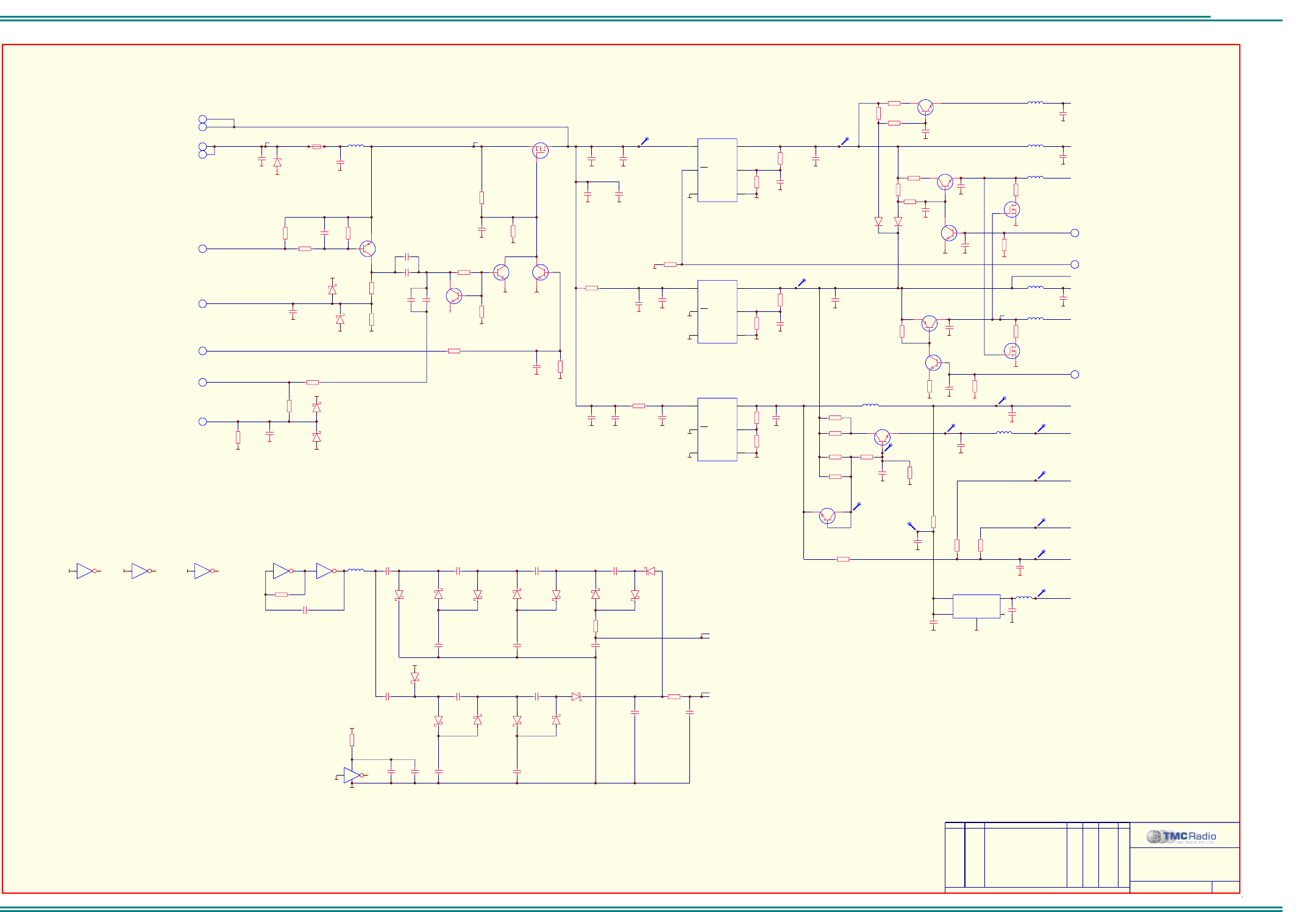
SRM9000X8 800MHz SERVICE MANUAL
© TMC Radio 2008 page 64 TNM-M-E-0022 Issue 1
TNM-M-E-0001
Sheet 9: Power Supply
ORDER DRAWN REMARKS EXAM APPD DATE REV
POWER SUPPLIES
SRM9000 RADIO BOARD
6102 349 6232
9 of 12
D900
1.5SMC16AT3G
0VA
13V8_UNSW
C915
100n
0VA
13V8_UNSW_F
L900
FB
FUSABLE LINK
+
C905
N.F. 0VA
10 13V8_UNSW
Q900
NTF5PO3T3G
(160mA Note 1)
C900
100n
Q902
BC859CW
R907
100K
R913
220K
0VA
PWR_ON
PWR_OFF
10
3
R908
10k
R922
4k7
0VA
C903
10n
PWR_SENSE
3
0VA
0VA
R903
10k
0VA
R906
10k
R924
680K
Q908
BC849CW
Q909
BC849CW
R902
15k
R905
22K
0VA
C916
1n0
0VA
1 3
D901A
BAT54SW
3V3
3 2
D901B
BAT54SW
0VA
0VA
Q907
BC849CW
2 AMP
IGN
10
R909
4k7
0VA
C937
100n
R911
15k
R910
4k7
0VA
1 3
D902A
BAT54SW
3V3
3 2
D902B
BAT54SW
0VA
3IGN_SENSE
C902
100n
C920
100n
C919
100n
C901
100n
0VA
5V_TX
5V_A
0VA
Q911
BC849CW
R931
4k7
R918
22K
0VA
2
TX_PON
R919
22K
C904
100p
32
D903B
BAT54SW
1 3
D903A
BAT54SW
C909
100n
C910
100n
C911
100n
32
D904B
BAT54SW
1 3
D904A
BAT54SW
C913
100n
32
D905B
BAT54SW
C912
100n
3 4
U904B
74HC04D
5 6
U904C
74HC04D
-12V
9 8
U904D
74HC04D
1 2
714
U904A
74HC04D
5V_D
0VA
Q904
BC859CW
R904
10k
0VA
5V_RX
0VA
Q906
BC849CW
R917
22K
0VA
2
RX_PON
C926
10n
0VA
C925
10n
0VA
Q916
BSN20
0VA
11 10
U904E
74HC04D
0VA 13 12
U904F
74HC04D
0VA
C939
N.F.
L910
FB
1 3
D905A
BAT54SW
C914
N.F.
32
D906B
N.F.
13
D906A
N.F.
16V
IN
4OUT 5
ADJ 1
ON/OFF
2
GND
3GND 6
UREG
U901
LM2931ACD2TR4G
Q917
BSN20
0VA
+
C923
22u
0VA 0VA
0VA 0VA
0VA0VA
IN
4OUT 5
ADJ 1
ON/OFF
2
GND
3GND 6
UREG
U912
LM2931ACD2TR4G
+
C938
22u
0VA 0VA
0VA0VA
8V_RF
R932
15k
R915
47R
R936
47R
L901
FB
L902
FB
L903
FB
L905
FB
5V_D
TP913 TP924
TP925
C918
100n
0VA
+
C941
10u
0VA
+
C931
10u
TX_PSU+
0VA
0VA
R934
220R
+
C949
N.F.
+
C932
N.F.
0VA 0VA
R946
10R
R925
22R
R916
22R
(16mA - Rx/72mA - Tx Note 1)
(60mA Note 1)
(10mA - Rx/19mA - Tx)
(22mA - Rx Note 1)
(17mA Note 1)
Note 1. Currents indicated are typical for radio only in Rx squelched mode
0VA
0VA
3Q3
0VA
0VA
Q910
BC849CW
3V3
L904
FB
R930
2k2
3C3
3P3
(14mA Note 1)
15.5mA
5.8mA
C907
100n
0VA
ON/OFF
3
OUT 5
GND
2
IN
1
N/C 4
U903
LP2981 IM5X-2.5/NOPB
0VA
0VA
2V5
L909
FB
C924
10u
R929
2k2
R948
150R
R947
150R
0VA
R952
2R2
TP964
TP965
TP966
TP967
TP968
TP962
3A3
0VA
R957
2R2
R958
2R2
R959
2R2
Q912
BC849CW
R901
1K8
TP963
TP960
TP961
TP969
C929
1n0
10 BAT_SW
IN
4OUT 5
ADJ 1
ON/OFF
2
GND
3GND 6
UREG
U900
LM2931ACD2TR4G
0VA0VA
3
STBY
0VA
R938
15k
R937
8K2
R933
N.F.
0VA
R912
100K
0VA
All Rights Reserved
1270 Ferntree Gully Rd Scoresby Australia 3179
C 2006 TMC Radio Pty Ltd ACN 099 952 977
O
F900
N.F.
0VA
0VA
L906
FB
C947
4n7
0VA
3
+
C921
47u
+
C950
47u
+
C943
47u
0VA
R914
N.F.
0VA0VA
C906
1u0
C908
1u0
C917
1u0
C930
1u0
C945
1u0
C951
1u0
C934
1u0
C933
1u0
C922
1u0
C936
1u0
C935
1u0
32
D960B
BAT54SW
13
D960A
BAT54SW
C960
100n
C961
100n
C962
100n
32
D961B
BAT54SW
1 3
D961A
BAT54SW
C964
100n
3 2
D962B
BAT54SW
C963
100n
1 3
D962A
BAT54SW
C965
N.F.
R960
1k0
5V_D
C940
N.F.
C927
N.F.
C942
N.F.
C928
N.F.
0VA
R935
1k0
R926
1k2
R927
6k8
Q905
BC849CW
R921
22R
Q903
BC849CW
R941
22R
23
D907B
BAV70W
13
D907A
BAV70W
C944
N.F.
0VA
5V_RF
L908
FB
0VA
C948
N.F.
.A09.10.06
..CM .. .INITIAL REALEASEU057
5
R940
1k0
R942
100R
R920
1k0
R923
100R
(40mA Note 1)
R900
220K
21.3mA
C946
100n
0VA
.B06.02.07
..CM .. .UPDATED TO REV BU089 .C21.06.07
..CM .. .UPDATED TO REV CU128
(53mA - Tx Note 1)
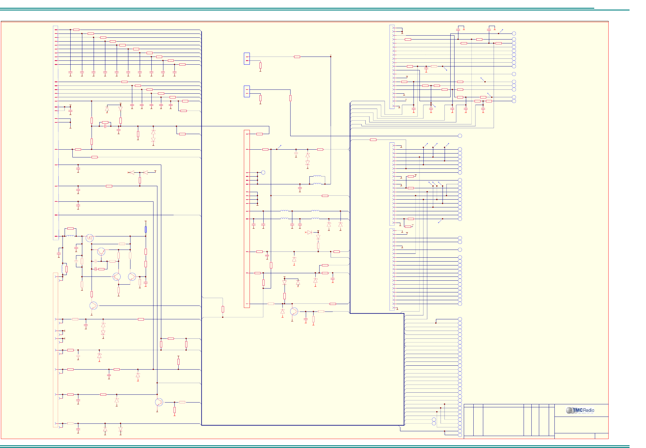
SRM9000X8 800MHz SERVICE MANUAL
© TMC Radio 2008 page 65 TNM-M-E-0022 Issue 1
TNM-M-E-0001
Sheet 10: I/O Connections
ORDER DRAWN REMARKS EXAM APPD DATE REV
I/O CONNECTIONS
SRM9000 RADIO BOARD
6102 349 6232
10 of 12
0VA0VA
C59
N.F.
P6
TEST PORT
7
12
13
9
19
17
14
10
8
2
23
5
4
3
25
1
6
13V8_UNSW_F
0VA
TXD
RXD
TFS
RFS
MF8
18 FC0
15
20
P1
OPTIONS CONNECTOR
C1
100p
0VA
C20
100p
0VA
C2
100p
0VA
C3
100p
0VA
C4
100p
0VA
C5
100p
0VA
C74
100p
0VA
C17
100p
0VA
C8
100p
0VA
C9
100p
0VA
C10
100p
5
7
8
4
6
3
1
2
0VA
0VA
R88
100R
R24
100R
R69
18k
3V3
R86
100R
TX_DATA2
Q1
BC849CW
R89
4k7
0VA
PF6
PF4
24
16
26
22
11
21
C6
100p
0VA
C7
100p
0VA
C22
100p
0VA
C23
100p
0VA
R23
3k3
5V_D
R90
22K
0VA
STX
SRX
C77
100p
0VA
0VA
R84
680R
C76
100p
0VA
R85
100R
RX_DATA2
0VA
0VA
R83
1k0
0VA
0VA
0VA
0VA
L50
FB
L51
FB
C78
10n
13V8_UNSW_F
OPTION ON/OFF
GROUND
MIC AUDIO
MIC GND
H/S AUDIO
ON/OFF
TxDATA
RxDATA
13V8
AUDIO/PWR ON
IRESET
SIN
SOUT
AUDIO OUT
L3D
SCLK
RFS
TFS
PF4
PF6
RXD
TXD
CONF2
OPTIONS PTT
SWITCHED
AUDIO_OUT3
AUDIO_IN1
OPTION
AUDIO OPTION_AUDIO1
13V8
SWITCHED
IRESET
C19
10n
0VA
R21
0R
L8
FB
C51
1n0 0VA
BATT_IN
C55
100p
0VA
4
5
1
2
11
12
9
10
6
13
C54
100p
0VA
SPKR_OUT1
SPKR_OUT2
L3
N.F.
3
7
PTT_IN1
0VA
0VA
L56
FB
L58
FB
L57
FB
L59
FB
R95
1k0
15
0VA
R94
N.F.
0VA
Q50
BCX54-16
R63
1k0
8
0VA
OUTPUT0
C58
1n0
14
R93
220R
PTT_IN2
S1
RJ CONNECTOR
P2
DB15 CONNECTOR
PWR_ON
8
8
13
D17A
BAV99W
32
D17B
BAV99W
1
2
P4
N.F.
0VA
9
0VA
13
D23A
BAV99W
R60
1k0
5V_D
32
D23B
BAV99W
C75
N.F.
EXTERNAL INTERFACE
13.8V UNSWITCHED
GROUND
CONTROL HEAD/MIC
MF19 (AUDIO I/P)
MF20 (AUDIO O/P)
BATTERY IN
GROUND
SPEAKER (+)
SPEAKER (-)
MF21 (IN#0)
IGN
MF23 (OUT#0)
R91
220R
R54
330R
R57
N.F.
0VA
R20
N.F.
L3D
L3M_B
L3C
R3
220R
CLRC
CCLK
3
IRESET
3
3
3
3
8
88
8
8
R18
N.F.
C13
100p
0VA
C12
100p
0VA
C14
100p
0VA 0VA 0VA
R16
330R
R15
220R
R14
220R
R13
220R
R12
220R
CCLK
L3D
L3M_B
L3C
SPKR_OUT1
SPKR_OUT2
AUDIO_IN1
AUDIO_OUT1
OPTION_AUDIO1
L3M
L3C
CLRC
AUDIO IN/CCLK
R2
100R
2
2
3
2
2
2
2
PF4
PTT_IN1
PF6
OUTPUT0
TFS
RFS
MF8
3
3
3
3
OPTION ON/OFF
RX_DATA2
TX_DATA2
FC0
13
D25A
BAV99W
32
D25B
BAV99W
R64
N.F.
R67
0R
R68
N.F.
5
7
8
4
6
3
1
2
0VA
Q6
BC849CW
0VA
R55
270R
0VA
0VA
Q7
NTF5PO3T3G
D50
BZX84-C18
12
R59
6R8
0VA
C18
10u
F1
MINISMDM110F/16
C52
4n7
R58
1k0
R98
100R
AUDIO_OUT2
9
S5
9
3
5
7
19
10
12
14
17
13
6
8
4
2
11
1
15
16
18
0VA
S8
9
3
5
7
19
10
12
14
17
6
13
8
4
2
11
1
15
16
18
0VA
OPTIONS PORT 1
M1
M2
0VA
M1
M2
0VA
0VA
2
2
2
2
2
2
2
2
2
2
2
3V3
/BG
/BR
EBG
EINT
EBR
ELIN
ECLK
ELOUT
EMS
EE
ERES
5
3
7
19
10
12
14
17
13
6
8
4
2
11
1
15
16
18
0VA
9
3
TCK
3
TRST 3
TMS
3
TDO
3
TDI
M1
M2
0VA
MF20
3
3
3
3
3
3
3
3
MF9
MF11
MF12
MF13
MF14
MF15
MF17
MF18
MF19
3
MF21
3
ANALOG_IN
3
MF23
3
MF16
3
MF10
0VA
3
RXD
2
3
3
3
3
3
3
2
3
MF8
TXD
3
3
3
3
3
2
OptionsPort 2
MF5
MF6
RX_DATA1
TX_DATA1
PTT_IN2
MF2
MF25
MF4
MF7
MF3
/RESET
MF24
3
BAT_SW 9
0VA
5V_D
3
0VA0VA
R46
N.F.
0VA
R47
N.F.
0VA 0VA
TP030
TP033
TP032
TP026 TP025
TP023
TP027
TP028
TP022
TP024
IGN
IGN
PWR_ON
AUDIO_OUT2
0VA
0VA
D19
BZX84-C18
0VA
R96
10k
32
D11B
BAV99W
13
D11A
BAV99W
5V_D
AUX 2
3
/RESET
8
8
8
CCLK
L3C
L3D
(BOTTOM SIDE)
(BOTTOM SIDE)
(BOTTOM SIDE)
D24
BZX84-C5V6
13
D22A
N.F.
5V_D
32
D22B
N.F.
0VA
D15
BZX84-C18
D16
BZX84-C5V6
MF23A
EXT_SENSE2
MF21A
MF20A
MF19A
MF23A
EXT_SENSE2
MF20A
MF19A
MF20A
PTT_IN2
TXD
RXD
D20
BZX84-C5V6
MF21A
C56
1n0
C57
1n0
R44
N.F.
R45
N.F.
C37
1n0
C36
1n0
C35
1n0
C53
1n0
C34
N.F.
R48
N.F.
R49
N.F.
R52
N.F.
R53
N.F.
R51
N.F.
R50
N.F.
R61
N.F.
R19
N.F.
C71
100n
0VA
D12
N.F.
0VA
D18
N.F.
D21
BZX84-C5V6
C50
100p
TP029
TP021
8
3
CLRC
CLRC
R10
100R
R9
100R
R8
100R
R7
100R
R6
100R
R5
100R
R4
100R
R1
100R
R11
100R
L3M_B
3
TFS
R29
N.F.
EXT_REF 7
1
2
P3
N.F.
R27
N.F.
R26
N.F.
AUX 1
0VA
AUDIO_OUT1
MF17A
All Rights Reserved
1270 Ferntree Gully Rd Scoresby Australia 3179
C 2006 TMC Radio Pty Ltd ACN 099 952 977
O
8
AUDIO_OUT3
AUDIO_OUT1
R22
0R
D28
BZX84-C5V6
D26
BZX84-C5V6
D27
BZX84-C5V6
D13
BZX84-C5V6
R43
N.F.
0VA
R42
N.F.
C33
1n0
R39
N.F.
0VA
R38
N.F.
C32
1n0
MF17A
R30
0R
MF10A
0VA
C25
N.F.
R41
N.F.
R40
N.F.
MF10A
R56
N.F.
R99
N.F.
R66
N.F.
TP34
DEEMPH_AUDIO
8
R92
N.F.
DEEMPH_AUDIO
13V8_UNSW_F
13V8_UNSW
FC0
OUTPUT0
TX_DATA3
R65
N.F.
TX_DATA3
R35
N.F.
R34
N.F.
3V3
5V_D
R36
N.F.
R37
N.F.
AUDIO_OUT1
R17
N.F.
(TXD1)
(MCK1)
(RXD0)
(TXD0)
(SCLK0)
(SW_BAT)
(RXD1)
(PTT)
(GND)
(GND)
(nRESET)
(MAB2 INTERFACE)
C15
N.F.
R79
4k7
0VA
0VA
R32
N.F.
R33
N.F.
0VA 0VA
R80
15k
R81
100K
Q8
BC849CW
Q9
BC849CW
R76
15k
R77
4k7
R75
4k7
R74
22K
Q5
BC859CW
R72
3k3
R73
3k3
C70
100p
C72
1n0
C69
N.F.
0VA
C16
33p
R71
1k0
C79
100n
8
AUDIO_OUT_4
0VA
R70
0R
R62
2k2
R78
100K
D10
BZX84-C4V7
R82
N.F.
R97
270R
R87
330R
Max 145mA
R28
N.F.
C73
1u0
.A09.10.06
..CM .. .INITIAL REALEASEU057
5
.B06.02.07
..CM .. .UPDATED TO REV BU089
R25
10k
0VA
.C21.06.07
..CM .. .UPDATED TO REV CU128
SRM9000X8 800MHz SERVICE MANUAL
© TMC Radio 2008 page 66 TNM-M-E-0022 Issue 1
Top Overlay
R48
C35
C908
C34
C37
R44
TP024
C204
R218
R832
C803
R935
C925
R917
R921
C4
C9
O
TOP COMPONENT OVERLAY
1270 Ferntree Gully Rd Scoresby Australia 3179
C 2006 TMC Radio Pty Ltd ACN 099 952 977
R38
R39
TP351
All Ri
g
hts Reserved
U167
800MHz RADIO BOARD
Q909
114 - 301
2
CJM
R17
C859
R922
C916
R905
D901
C903
C902
R902 C901
R907
Q902
R900
C900
D15
C920
C919
R906
R913 Q907
TP028
D25 D27
R24
D16 D13
TP925 R55
TP858
R54
C74
C950
TP966
Q905
D17
C78
R91
TP203
TP307
R327
R333
TP360
TP359
TP306 TP021
TP371
C33
R328
R326
R330
C325
TP026
TP320
TP304
TP201
C328
R339
R42
R43
C318
C319
TP330
R316
R69
R302
R334
TP303
R331
R335
R358
C327
C326
TP302
TP801
C800 TP820
R858
R860
C854
R340
C849
R851
U803
R849
R82
C858
R857
R856
C855
R908
C853
TP842
TP964
R847
R846
C862
R843
R831
R835
TP851
C852
R850
R855
C848
TP849
R359
6102 309 6232
C58
R62
R911
C313
R910 R909
R237
D902
R63 C57
Q50
R61
R353
R58
R51
TP222
R19
R94
C18
C25
R40
R41
TP250
C32
R50
R56
R45
TP033
R52
C53
R49
R53
TP202
R66
MF1
TP804
CF8
R13
C5
R12
R18
C12
C69
R68
C22
R64
C14
R14
R67
C20
C17
C15
R15
R5
R11
TP327
CF9
C307
C788
R797
TP408
C721
C722
R406
C410
C782
C59
R763
C773
C775
C774
C729
R92
TP803
D12
L900
C915
D18
C50
C54
TP34 D22
L57
R861
TP853
C872
C871
C869TP854
C868
C867 TP240
C866
TP210
C220
R233
TP241
R216
R238
R332
TP242
R234
TP243
R201
CF3
C223
TP211
C222
R217
Q200
C207
TP212
C203
C206
C205
R20
R25
C19
D24
C709b
D26
L59
C55
C489
C942
R485
C481
TP809
R369
C221
R706b
R370
L909
C924
R706
C709
R706a
TP808
R706e
R706c
R706d
C707
U701
R236
U201
U202
U903
R228
R231
C218
C708
R792
C702
D780
R232
C219
R354
R351
C349
C937
R322
TP224
L780
R791
C781
TP368
Q783
C786
C787
C705
Q781
C784
R794
R789
Q780
R793
C783
R783
R790 R786
R714
R787
C780
R796
Q782
R795
D782
R788 R717
R716 C728
C725
C724
R494
C494
R493
R492
C493
L58
R490
R491
R496
R497
C492
C490
U491
R488
R486 R489
R487
R495 Q774
R752TP746
C488
TP743
TP744
R750
C765
C766
C495
L3
C491
TP460
R483
C486
R751 R753
L751
R754
Q751
C772
R758f
R760
C771
R758a
U760
R758b
TP747R768
R765
R764
Q776
Q775
R762 TP748
R766
C723
TP711
R769
C726
TP720
U721
C776
C777
R703
R702
R701
R700
C701
R767
C770
R758e
R770
R759e
R759f
R759a
R758c
R758d
R759b
Q771
R772
R771
C778
Q772
Q773
R774
R776
R759c
R759d
TP745
C779 R773
C768
F900
C51 C52 R93 R87
L56
C571a
L8
D900
C571b
C571c
Q601
R616
Q452
Q453
R323
U300
C347
R349
C334
L301
R807
R312
C346
R363
C332
R314
C309
CF4
R37
R36
R214
TP968
R215
TP027
R212
R823
R34
R820
C819
R822
U800
R308
R804
C805
C348
R336
R348
R798 R 784
R799
R615
R731
R785
C635
R310
C343
TP343
C608a
C841
R342
R841
TP811
C655
C608
C604
U601
R603
R651
TP309
C604a
R810
TP840
R815
C870 C861
R869 R324
TP852
R809
C844
R808
C801 R805
R806
TP301
TP850
U302
R862 R802
R870
R874
TP802
R801
R800
R803
TP841
C344
U801
R840
C317
C804
C802
C811
R350
R811
C813
R824
TP805 TP810
R616a
Q602
C842 D801
C809
R357
R365
C324 TP411
D301
R366
R367
C450
C353
R321
TP300
Q451
TP410
TP412
Q908 R924
C926
R918
Q900
C922
C906
C930
C931
Q911 C940
R904
Q917
C921
C933
Q904
R936
Q916
R915
C354 R16
R450
R914
TP415
C452 R453
R454 R455
R459
TP414
R458
Q454
TP416
TP965
R452
R457
L905 L902
R456
C451
R451
TP367
Q6
R79
Q906
R920
Q903
R941
C928
R912
R940
R923
D907
R942
TP913
L908
C917
D10
C948
C6
R6
R1
C23
C1
R2
C2
C13
R8
R9
R4 C8
R70
R71
R77
C73
R81
Q9
C79
C72
Q5
R74
Q8
R75
R10
R7
R3
C7
C10
C3
C16
R78 R80 C7 0
R76
F1
R72
R73
TP680
TP681
TP692
TP501
TP521
TP531
TP682
Q7
TP691
C720
R715
C603
R604
C601
R601 C600
C607a
C607
R609
R611
R606
R613
R607
R612 R614
C606a
C602 C605
C606
C609a
C609
R654 R653
R652
C656
L642
R648
C659
Q640
R647 R649 R650
TP601
C617
C657 C649
TP652
R656
C642
L641
R642
R644
E601
R645
C653
C611
R602
C615
R605
C610a
R657
C610
L651
C642a
TP651
R643
L650
R658
C660
R605a
TP650
C661
U650
R659 TP661
C663
L652
L653
R663
C662
R661
D641 D642
R662
TP653
C664
R600
R610
C654
TP441
C574
C665
C576 C575
R556
D551
Q551
R360
C551
R558
C578a
R571 R572
C578b
C578c
C572
R407
C568
L561
C569
R569
C550
R557
C556
D561
R565
L571
L572
C557
R566
TP561
R405
C579c
C579b
C579a
R409
Q402
C417
Q403
C418
R408
6102 309 62322
SRM9000X8 800MHz SERVICE MANUAL
© TMC Radio 2008 page 67 TNM-M-E-0022 Issue 1
Bottom Overlay
TP362R833 TP30 8
C941
C949
P3
C932
1270 Ferntree Gully Rd Scoresby Australia 3179
C 2006 TMC Radio Pty Ltd ACN 099 952 977
O
TP366
All Ri
g
hts Reserve
d
BOTTOM COMPONENT OVERLAY
6102 309 6232 2
TP349
L904
TP969
R871
R89
R90
Q1
TP961
R933
R930
TP960 TP962
C929
Q910
C945
R361
R958
R959
R901
R957
Q912
R23
R88
C76
R85
R86
1
C77
R84
R929
R83
C75
R903
S2
S5
C320
R317
U301
TP350 TP029
TP361
C824
R834
C857
R872
TP857
R875
C839
C825
R876
TP856
U806
800MHz RADIO BOARD
CJM
U167
114 - 302
C865
C864
P6
TP204
TP030
C200
TP342
R47 TP032
C36
R46
Q810 R863
R868
R853
R865
Q813
CF7
R864
R867
P1
1
CF6
R224
R329
R301
TP348
C323
C464
C409
R28
R576
R578
D402
C336
C337
R817
TP967
R303
R466
TP373
L406
R402
C426
R412
C422
C538
D19
C829
D20
D23
C56
R725
C833
R852
R866
Q811
C873
R854
C863
C831
D21
C832
C830
C856
C860R859
U805
R99
U200
BK
X200
C209
R219
C208
X200a
C951
C335
R208
C907
C216
TP963
D28
D730
C734
R719 D731
R720
L730
C738C745
C739
C735
R721
R724
C737
C706
R718
C732
L703
R705Q700
C733
C743
R722
C742
R704
C714
TP208
C217
R206
R209
R203
TP219
TP205
C210R205
R223
TP221
TP228
R202
R225
R230
R207
C202
TP225
R227
TP215
TP207
TP341
TP209
TP346
TP213
R204
R211
C201
C213
R210
TP214
R325
TP345
TP229
C211
C215
R222
R229
R220
C214
R952
L701
C704
U711
TP713
C718R712
TP714
C712
R235
C212
C310
R311
C303
R304
TP344
R344
R221
R364
R352 R813
R708
R707
TP347
C746
R730
C747
C741
C748
Q730
R727
R729
C740
R728
C755
R737
R733
R738
C757
C750
L732 R734
C751
R740R735
Q731
R732
C744
Q734
R736
C754
E700
L734
R742
L733
R739
C758
R743
R499
C498
L492
C497
R480
C466
R482
R60
L491
D50
C496
R498
U481
C487
Q571
C485
C482
R477
C483
C484
R475
C476
R476
R484
C480
C581
R575
C479
R574
C577
C715
C717
C716
U712
C719
R712a
TP715
R713
C769
R747
R748
E701
C762
R746
C761
R775
C713
R710
TP712
C711
Q712
R711
R709
Q711
R777
C767
C760
U761
R778
R745
C763
C475
Z471B
C474
BK
C473
BK
C472
C471
Z471A
C582
L409
D401
Z400
L407
R414
RD
C470
R474
C468
C411
C412
R473
C413
U401
L402
R404C405
L408
C414
Q404
Q401
P2
R97
R57
R95
P4
C905
R29
C764
R98
R96
D11
R59
R671 U620
C674 C638
R552
C682
C679
L661
CF1
Q670
L665
C682a
D682
C689R686
C338
TP363
C340
C339
C341
C330
C943
C314
C329
C331
C342
TP354
R816
TP372
TP358
TP364
C316
TP355
TP352
C315
R341
TP314
C322
R320
C300
R319
C321
TP328
TP305
TP022
R346
C302
R345
R356
TP310
C301
R35
R315
TP023 TP025
TP370
TP356
R337
C345
C333
R355
R309
C305
C308
C312
TP331
R318
TP313
R623
R306
TP316
R629
C638a
L300
R300
R821
C311
R313
C304
R305
R814
C306
C807
R307
C636a
R630
R631
R634
R812
R655
R65
TP833
S8
C816
C352
U802
TP855
C818
C820
U904
C934
C939 C817
R946
L910
C904R919
R826
R827
R347
R30
R21
L906
R362
R22
C961
D960
C912
C960
D961
C962
C963
TP831
C350
R818
C815
TP807
C909
C840
C911
TP311
C806
Z620
R819
R825C814
C935
C812
R343
D903D904
C913
C914
C910
C964
D962
D905
C965
D906
R934
C351
R960
C936
R668
C938
R925
R937
R938
R947
C923
R916
R948
C918
R932 R931
U912
R677
R671a
R676
L672
C684
L903
U901
R681
R680 Z682
Z684
R33L50
C71
L51
C946
C944 R32
C947
R926TP924
R927
C927L901
C687
D684
U900
2
R672
C678
C680
R673
C681
D681
C683R675
R684
R674
R683a
C658a
R683
Q681
R682
C688
Z681
Q682
R678
R688
R683b
R697
C502
C504
R502
C509
C508
L501
R699
C501
Q501
R553
R554
R559
C553
C555
R562
C552
R561
R564
C560
C563
R524
Q522
R523
R532
R528
R505
C513
C518
C516
C515
E603
C511
R512
R522
C525
R514
C524
C530
R525
R527
R531
C532
C523
R526
C531
R529
C685
R679
C699a
Z683
R685
C699
R696
C698
C697
R501
R503
R698
C503
R695
L692
C686
D683
Q691
R687
C691
C693
R692
R689
L691
R691
C690
R694
C695
R690
C692
C696
R693a
R693
C507
R513
R515
C512
R504
C506
R511
L502
L511
Q521
C526
L522
C533
C527
R530
C694
C514
C517
R516
R520
L521
C522
C521
R521
R26
R534
R27
R646
C636
D622
C637
R633
TP631
C647a
L623
D623
R632
R639
C647
R641
Q632
Q631
L624
C651a
R636
R638
C645
C651
C648
R637
D621
C641
R628
C639
R629a
C640
C643
C625
Q623
C631
R627
C624
C630
C646
R635
C629
C633
R626
Q622
R624
Q621
L622
C627
C632
R625
R472
C465L463
R469
Q461
C463
R640
C644
C467R 471
R468
C462
C408
C400
C415
R403
C424
R467 C469
L462
R421
C644a
C650
C461
R626a
C460
R462
C628
E600
R463
C459
R461
C447
C431
C430
L461
C434
D431
C433
R422
C435
R465
C432L431
Z430
C622
L601
C612
C613
D610
C614
C620
C634
C616
R619
C619a
C621a
R620
R622 L621
R608
R621
D624
R618
C619
C623
C618
C658
R617
L670
C675
L664
C670
C672
C676
C677
R669
R670
D661
C673
L663
L662
C667a
C666
R664
R666
R665
C671
C668
C669
R625a
C621
C626
R428
L449
R424
R621a
R427
R426 L448
U441
C445
L432
C437
C443
C436
C499
Z431
C441
C440
D432
R423
C438
C667
R541
R540
R543
R544
R545
D660
R667
E602
C543
R547
R551
R546
R542
C573
C439
C542
C541
R548
R549
U551
R563 C554
R560
R568
E401
C567
C566
R533
Q532
R535
Q531
Q531a C535
C539
C536
U561
C562
C534
R536
E503
L531
R539
C537
R537R538
R567
C565
S501
MF4
Q572
R579
R573
C595b
C596
C595
R577
Q573
C586
C580
C585
R591
C599
R594
L594
C598
C595a
C598a
E502
R593
C593
C592
L593
C592a
C592c
C401
L401
C421
C419
C403
C404
C406
C407
L405
C587
E402
D580D582
C583
C584
D583
C588
L592
L581
L591
L573
D581
C589
C592b
E501
R592
C590

SRM9000X8 800MHz SERVICE MANUAL
© TMC Radio 2008 page 68 TNM-M-E-0022 Issue 1
APPENDIX A - GLOSSARY OF TERMS
A summary of common radio terms and some other terms used in this document, and their meanings, are given
below.
ADC Analog to Digital Converter.
AFC Automatic Frequency Control.
AGC Automatic Gain Control.
Alarm A Selcall sequence sent from subscriber equipment to indicate an Emergency situation.
When activated the radio will enter a repeating sequence consisting of an Alarm Live
Transmit Time and an Alarm Dead Receive Time.
Certain special conditions for the radio may also occur during the alarm.
A dedicated SFM (trunked system) that is sent by pressing the Alarm Key.
ANI Automatic Number Identification.
Auto Interrogate An Acknowledge identity sent as a response to an individual reset call.
Automatic Power Feature whereby the transmit power is automatically set to a level determined by the
level of the received signal. This is used to extend the battery life and/or reduce radiated
emissions.
Automatic Volume Feature whereby the background audio level is monitored and if this is found to be noisy
then the volume level is increased to compensate, allowing the user to hear better.
Busy The state of a channel such that:
• For a non-signalling channel - if Busy this means that the carrier is above squelch.
• For a channel with CTCSS/DCS - if Busy this means a signal is being received with
either no CTCSS tone / DCS code or the correct CTCSS tone /DCS code.
• For a channel with Selcall - if Busy this means a closed channel where the signal is
above squelch.
A feature that equates to 'Do Not Disturb' such that the radio will reject all non-
emergency calls. This feature can be activated using the Busy key (if assigned) or from a
menu; it is reset to disabled at switch on.
C4FM Compatible 4-Level Frequency Modulation.
Call Back A request, sent by the dispatcher, to a unit requesting that the unit calls the dispatcher
back.
Channel Spacing The distance (in kHz) between the defined frequency channels.
Clipboard A temporary storage area in Windows used to store data in cut, copy and paste
operations.
Closed A state where transmit and receive are not allowed until a Selcall message to open the
channel has been received. A Closed Channel is one which defaults (when selected or
after timed reset) to its closed state. Contrast with Open. Normally a Closed channel
would have Selcall Mute and PTT Inhibit would be enabled.
CODEC COde (Analog to Digital Converter) / DECode (Digital to Analog Converter).

SRM9000X8 800MHz SERVICE MANUAL
© TMC Radio 2008 page 69 TNM-M-E-0022 Issue 1
Community Repeater A communications set-up whereby different groups of radios can operate by using only
one base station. This is achieved by the use of CTCSS tone signalling such that each
group has a different CTCSS tone (encode and decode) and radios can only
communicate with other radios in their group. Only one group of radios can use the base
station at any one time.
CRU Central Repair Unit
CTCSS CTCSS stands for Continuous Tone Controlled Signalling System. A continuous tone
(lower than the audio range of the receiver) is modulated onto the carrier as well as other
signalling or voice traffic. Compare with DCS. Only receivers that have been instructed to
recognise the same CTCSS tone are able to receive the transmissions, since the squelch
of receivers looking for different CTCSS tones prevents the audio from being heard. This
provides a simple method of sending messages to selected receivers only and allows
several different networks to use the same frequencies. CTCSS is also known as Tone
Lock or Tone Squelch.
DAC Digital to Analog Converter.
Dash (-) digits Digits known as 'No Tone' digits used in Selcall Identities.
DCS Digital Coded Squelch system is based on sending a continuous stream of binary code
words using, low deviation, direct frequency shift keying. Only receivers that have been
instructed to recognise the same DCS sequence are able to open their squelch and
receive the associated speech transmissions. This provides a simple method of sending
messages to selected receivers only and allows several different networks to use the
same frequencies.
Decode Reception of signalling. Either Selcall where encoded tone frequencies are decoded and
identified as specific tones digits or CTCSS/DCS where tones are analysed to see if the
channel should be opened.
Disabled The 'False' state of a parameter. That indicates this parameter is not active. Typically this
state is represented by an unmarked check box. Compare with Enabled.
DSP Digital Signal Processor.
DTMF Abbreviation of Dual Tone Multi-Frequency signalling. Used to dial into Telephone
networks using tone dialling.
Dual Watch A facility that enables the Radio to periodically monitor another channel for a signal
above squelch. Typically applications are checking an emergency channel whilst on
another channel.
Economiser A process by which the Receiver is powered down whilst there is no received signal.
Periodically the receiver is powered up to check for such a signal. This is used to extend
the battery life.
Enabled The 'True' state of a parameter. That indicates this parameter is active. Typically this
state is represented by a mark (either a tick or a cross) in a check box. Compare with
Disabled.
Encode Transmission of signalling. Either Selcall where Selcall tone digits are encoded into tone
frequencies or CTCSS/DCS where tones modulated onto the channel's carrier.
External Alert A facility for switching on various ancillary devices to meet customer's individual
requirements (e.g. car horn, flashing lamp etc.) when 'called'.
Only available on a mobile radio. To make available: go to Hardware Components,
Terminal Settings and set Product Type to a Mobile type.
Fallback A mode of operation that may be entered when the Network is suffering a malfunction.
During this mode certain facilities (e.g. PSTN) may not be available.

SRM9000X8 800MHz SERVICE MANUAL
© TMC Radio 2008 page 70 TNM-M-E-0022 Issue 1
FFSK Fast Frequency Shift Keying. This is a signalling system for the transfer of digital
information. It works by using one of two audio tones to represent transmit data..
Fleet A group of units formed such that only a shortened form of dialling (2 or 3 digits) is
required between them. These groups are normally assigned contiguous ident's.
PLA Programmable Logic Array.
FPP Field Personality Programmer.
Hash (#) digits These digits are used for two purposes:
• For Selcall identities (encode and decode) - known as User Id digits. These digits are
replaced by the user id entered at switch on (if enabled)
• Use in DTMF dialled strings - their use is network dependent to access special services.
Identity Name given to a sequence of tones which is used in sequential tone signalling. See Valid
Selcall Digits.
Idle State The state of the radio when it is not in a call.
Inaccessible A state of a channel such that it is unavailable to the user through normal methods of
channel selection. Therefore inaccessible channels will not appear on the channel menu.
Link Establishment A delay incorporated into the start of every selective call or DTMF transmission
Time which allows for the finite delay of the radio equipment in responding to any radio signal.
This includes both the commencement time of the originating transmitter and the
response time of the receiver.
Locked A state of a channel whereby it is not possible to change channels using the normal
up/down keys on the channel menu until the OK key is pressed. See Auto Channel
Selection Lock.
Null Id A Selcall identity that is not defined and whose tones' field is displayed as a blank.
Open A state where transmit and receive are allowed. The channel is no longer open when
reset. Contrast with Closed.
Normally an Open channel would not have Selcall Mute and PTT Inhibit would be
disabled.
PABX Private Automatic Branch Exchange.
Password An optional password system available on the radio. This feature is only available if the
radio has a display and a keypad. To make available: go to Hardware Components,
Terminal Settings and set Product Type to one which has a display and a keypad.
PLL Phased Locked Loop.
PMR Private Mobile Radio (not normally trunked).
Priority Channel A channel in a search group that is scanned between every other channel.
PSD Peak System Deviation.
PSTN Public Switched Telephone Network.
PTT Press To Talk. This is the term given to the operator’s key normally used to commence
transmitting a message.
PTT Inhibit A state whereby transmission using the PTT is not allowed. Also know as Tx Lockout.
PWM Pulse Width Modulation.

SRM9000X8 800MHz SERVICE MANUAL
© TMC Radio 2008 page 71 TNM-M-E-0022 Issue 1
Reference Frequency Normally this is generated from a high stability crystal oscillator reference and is divided
digitally in a frequency synthesiser for comparison with other frequency sources, e.g. a
VCO.
Repeat Tone A selcall tone that is used to replace repeated tones. Fixed at tone E.
Example: An identity entered as '12333' would be sent by the radio as '123E3'.
Reset Resetting is caused by Three Tone Reset, a Remote Reset, an Individual reset or a
Group reset (Call Types in Decode Identity). When a radio is reset the effect on the radio
will be as follows:
• Any Call Alerts will be stopped
• The Call LED flashing will stop
• If the channel is in Open mode then the channel is closed
• The PTT is optionally inhibited see PTT Inhibit After Reset Sequence.
• In searching - if paused on a selcall channel then searching resumes
• If the Acknowledge property of a Decode Identity is set to 'Auto Interrogate' or
'Transpond & Auto Interrogate' then the Auto Interrogate encode identity is transmitted.
RSSI Received Signal Strength Indicator.
Scanning Process of switching between the channels in the nominated search group in cyclic
sequence, stopping when the search condition (which may be to look for either a free or
a busy channel) is satisfied.
Search Group A group of channels that are either scanned for a signal above the search threshold or
are compared and voted for the strongest signal
Selcall Selective Calling - a system of signalling which allows 'dialling up' of specific mobiles,
portables and controllers. Such a system may be used to pass messages as a data
message to a specific user or group of users. It can be used to provide remote switching
facilities and to provide access control into community repeaters or similar devices.
Selcall Mute A state of the audio gate whereby the loudspeaker is muted (closed).
Selcall System Selective Calling, uses a tone sequence at the start, and end, of a call to control which
members of a fleet react to the transmission.
Sidetone Sidetone is the audio which can be (optionally) heard when Selcall, DTMF and toneburst
transmissions are made.
Simplex Mode of operation whereby the radio operates as a conventional fixed channel radio
outside the Trunking network.
Squelch System used to prevent weak, unintelligible signals and random noise from being heard
by a radio operator while still allowing intelligible signals to be received normally. This is
accomplished by the use of a threshold below which any received signals are ignored.
Only signals whose signal-to-noise ratio is above the squelch level cause the audio
circuits of the radio to be enabled, with the result that only satisfactory signals are
received. The squelch level is specified in SINAD.
Star (*) digits Digits known as Status or Message digits. These digits are used for three purposes:
• Status Digits for Selcall Identities
• Wildcard digits in Status strings
• Use in DTMF dialled strings - their use is network dependent to access special services.
Status A feature whereby a radio's status (or usually the status of the radio's user) can be
transmitted and a status message from other radios can be displayed. This operates

SRM9000X8 800MHz SERVICE MANUAL
© TMC Radio 2008 page 72 TNM-M-E-0022 Issue 1
through status digits in Selcall identities. Either in Encode Identities or Decode Identities
as follows:
Encode Identities: Status digits within the identity are used to transmit the current
situation of the radio's user (e.g. "Out To Lunch").
Decode Identities: Status digits are looked up in a table (Status Menu) for possible
messages to display.
SW Software.
TCXO Temperature Compensated Crystal Oscillator.
Three Tone Reset This is a system whereby a call to a user automatically reset all other users in a group.
Example: a call to user '12345' would call 12345 and reset all other users on this channel
with an identity 123nn where n can be any digit 0-9, A-F.
Tone Burst An audio tone is transmitted at the start of transmission to inform a relay (repeater)
station to switch itself on to relay the transmission.
Transpond An Acknowledge identity sent as a response to an individual call.
Tx Inhibit A facility which prevents the user from transmitting,(other than alarms), while the channel
is Busy.
User Identity This is a sequence of up to four digits entered by the user when the Radio is switched
on, if this option is programmed. These digits are then substituted into any transmitted
Selcall identity which includes # digits.
VCO Voltage Controlled Oscillator.
Vote Method used to compare the signal strength on a current channel with another specified
channel and then to choose the channel having the stronger signal.
Voting Feature used during searching when there is more than one channel that satisfies the
required conditions. It involves examining all the channels that satisfy the required
conditions, and then selecting the channel with the highest signal strength.
VOX
Voice Operated Transmit.