Simoco Wireless Solutions SRMA9000AC VHF MOBILE TRANSCEIVER User Manual USERS MANUAL A
Simoco Australasia Pty Ltd VHF MOBILE TRANSCEIVER USERS MANUAL A
Contents
- 1. USERS MANUAL A
- 2. USERS MANUAL B
USERS MANUAL A

P25 SRM9030 / SRM9030plus
Mobile Radio
P25 – Conventional / Trunked
Operating Instructions
TNM-U-E-0094 Issue 1.2a
ComGroup Australia Pty. Ltd.
1270 Ferntree Gully Road
Scoresby
Victoria, 3179
Australia
ISO9001 Lic.QEC20848
SAI Global

SRM9030-P25 RADIO – OPERATING INSTRUCTIONS
© ComGroup Australia 2010 page 2 TNM-U-E-0094 Issue 1.2
ASSOCIATED DOCUMENTATION
The following documentation is available for use with the SRM9000 series of products:
TNM-U-E-0079 P25 SRM9030 Mobile Radio Brief User Guide
TNM-P-E-0006 P25 SRM9030 Product Manual
TNM-I-E-0005 SRM9000 Installation Sheet
TNM-M-E-0002 SRM9000 R9 Service Manual
To order copies of any of the above publications, or any other ComGroup Australia product,
contact ComGroup Australia on +61 3-9730-3800 or send a Fax on +61 3-9730-3968.
The ComGroup Australia web site also has a comprehensive list of documentation available
for download.
http://www.comgroup.net.au
ABOUT THIS DOCUMENT
This publication is copyright and no part may be reproduced without prior permission of
ComGroup Australia.
Due to our policy of continuous improvement to our products and services, technical
specifications and claims, correct at time of publication, may be subject to variation without
prior notice.
ComGroup Australia has endeavoured to ensure that the information in this document is
fairly and accurately stated, but does not accept liability for any errors or omissions.

SRM9030-P25 RADIO – OPERATING INSTRUCTIONS
© ComGroup Australia 2010 page 3 TNM-U-E-0094 Issue 1.2
SAFETY
1. Do NOT operate your radio, without a hands free kit, whilst driving a vehicle.
2. Do NOT operate your radio in an explosive atmosphere.
Obey the 'Turn Off Two-way Radios' signs where these are posted, e.g. on a
petrol station forecourt.
3. Do NOT touch the antenna while the radio is transmitting.
HINTS FOR USING THE RADIO
• When speaking, hold the microphone a few centimetres from your mouth and speak
across it, rather than into it.
• Keep the length of your conversation to a minimum and replace the microphone on its
cradle after use.
• When it is possible to move location, avoid making calls from known poor signal-strength
areas such as the radio systems fringe areas (limit of range) or from screened or
shadowed areas, e.g. an underground car park or underpass.
• To avoid unnecessary drain on the vehicle battery, keep the engine running when using
the radio for extensive periods of time.

SRM9030-P25 RADIO – OPERATING INSTRUCTIONS
© ComGroup Australia 2010 page 4 TNM-U-E-0094 Issue 1.2
CONTENTS
1. INTRODUCTION..................................................................................................6
1.1 Overview ......................................................................................................6
1.2 Configuration ..............................................................................................6
1.3 Modes of P25-SRM9030 Operation ............................................................6
2. CONTROLS .........................................................................................................7
3. MENU SYSTEM.................................................................................................10
3.1 Menu Navigation .......................................................................................12
4. MENU SCREENS ..............................................................................................14
4.1 Channel Screen.........................................................................................14
4.2 Menus.........................................................................................................18
4.2.1 Zone Menu ..............................................................................................18
4.2.2 Squelch ...................................................................................................19
4.2.3 Mute Adjust .............................................................................................21
4.2.4 Phonebook Menu ....................................................................................22
4.2.5 Phonebook Edit Menu .............................................................................23
4.2.6 User Options ...........................................................................................27
4.2.7 Contrast...................................................................................................28
4.2.8 Alert Volume............................................................................................29
4.2.9 Radio Information ....................................................................................30
4.2.10 Mode Menu .............................................................................................32
4.2.11 RSSI (Received Signal Strength Indication) ............................................33
4.2.12 Crypto......................................................................................................34
4.2.13 Setup Menu .............................................................................................35
4.2.14 Stored Calls.............................................................................................36
4.2.15 ....................................................................................................................36
4.2.16 Messages ................................................................................................37
4.2.17 Scan Edit Menu .......................................................................................45
4.2.18 No Menu..................................................................................................47
5. COMMON FUNCTIONS AND FACILITIES .......................................................48
5.1 Switch-On/Switch-Off ...............................................................................48
5.2 Default Screen –Trunked Mode ...............................................................48
5.3 Volume Adjustment ..................................................................................48
5.4 Receiving (Single Channel Screen) .........................................................48
5.5 Received Individual Calls .........................................................................49
5.5.1 Stored Calls Screen.................................................................................50
5.5.2 Received Call Pop-Up Menu ...................................................................50
5.6 Transmitting ..............................................................................................51

SRM9030-P25 RADIO – OPERATING INSTRUCTIONS
© ComGroup Australia 2010 page 5 TNM-U-E-0094 Issue 1.2
5.7 Scan/vote Functions .................................................................................51
5.7.1 Scan/Vote Screen....................................................................................52
5.8 Keypad Lock..............................................................................................53
5.9 Encryption .................................................................................................53
5.10 Emergency Alarm..................................................................................53
5.10.1 Receiving Emergency Calls.....................................................................53
5.10.2 Making an Emergency Call......................................................................53
6. SPECIAL FUNCTION KEYS .............................................................................55
6.1 Alarm..........................................................................................................55
6.2 Channel Up and Down ..............................................................................55
6.3 Crypto ........................................................................................................55
6.4 Low Power .................................................................................................55
6.5 Menu...........................................................................................................55
6.6 Mode...........................................................................................................55
6.7 Mute............................................................................................................55
6.8 Reset ..........................................................................................................55
6.9 Scan ...........................................................................................................55
6.10 Scrambler...............................................................................................56
6.11 Talkaround .............................................................................................56
6.12 Zone........................................................................................................56
6.13 Undefined...............................................................................................56
7. APPENDICES....................................................................................................57
7.1 Alert Tones And Messages ......................................................................57
7.2 Glossary.....................................................................................................58
7.3 Acronyms ..................................................................................................59
7.4 Compliance with RF Energy Exposure Guidelines (United STATES and
Canada)................................................................................................................60

SRM9030-P25 RADIO – OPERATING INSTRUCTIONS
© ComGroup Australia 2010 page 6 TNM-U-E-0094 Issue 1.2
1. INTRODUCTION
1.1 O
VERVIEW
The Simoco SRM9000 Series Radios are a family of versatile Digital Signal Processor (DSP)
controlled, software controlled two-way mobile radios.
These Operating Instructions describe the operation of the APCO P25 Standard compliant
Mobile Radio, consisting of an SRM9000 Transceiver, a MA-MAB-2 Option Board, and
SRM9030 / SRM9030plus Control Head.
The SRM9030-P25 Radio may be customised to your operational requirements using the
Field Personality Programmer (FPP). Your Simoco representative can help in programming
your radio facilities to meet your present and future requirements.
1.2 C
ONFIGURATION
The SRM9030-P25 Radio must be configured using the P25 Field Personality Programmer
(FPP) prior to operation. The configuration process defines the radio channels, signalling and
other settings so that the radio will operate with your system
1.3 M
ODES OF
P25-SRM9030 O
PERATION
The SRM9030-P25 Radio is capable of operation in Analogue FM, Analogue Trunking, P25
Conventional and P25 Trunked modes.
Radio Channels are organised in groups of up to 250 per zone. Up to 40 zones may be
defined.
Generally, zones can be programmed with channels belonging to common function groups.
A radio channel can be defined as either Analogue, Conventional P25 Channel or Trunked
P25 network, and a Zone may contain a mix of Analogue or Conventional P25 Channels.
SRM9030-P25 RADIO – OPERATING INSTRUCTIONS
© ComGroup Australia 2010 page 7 TNM-U-E-0094 Issue 1.2
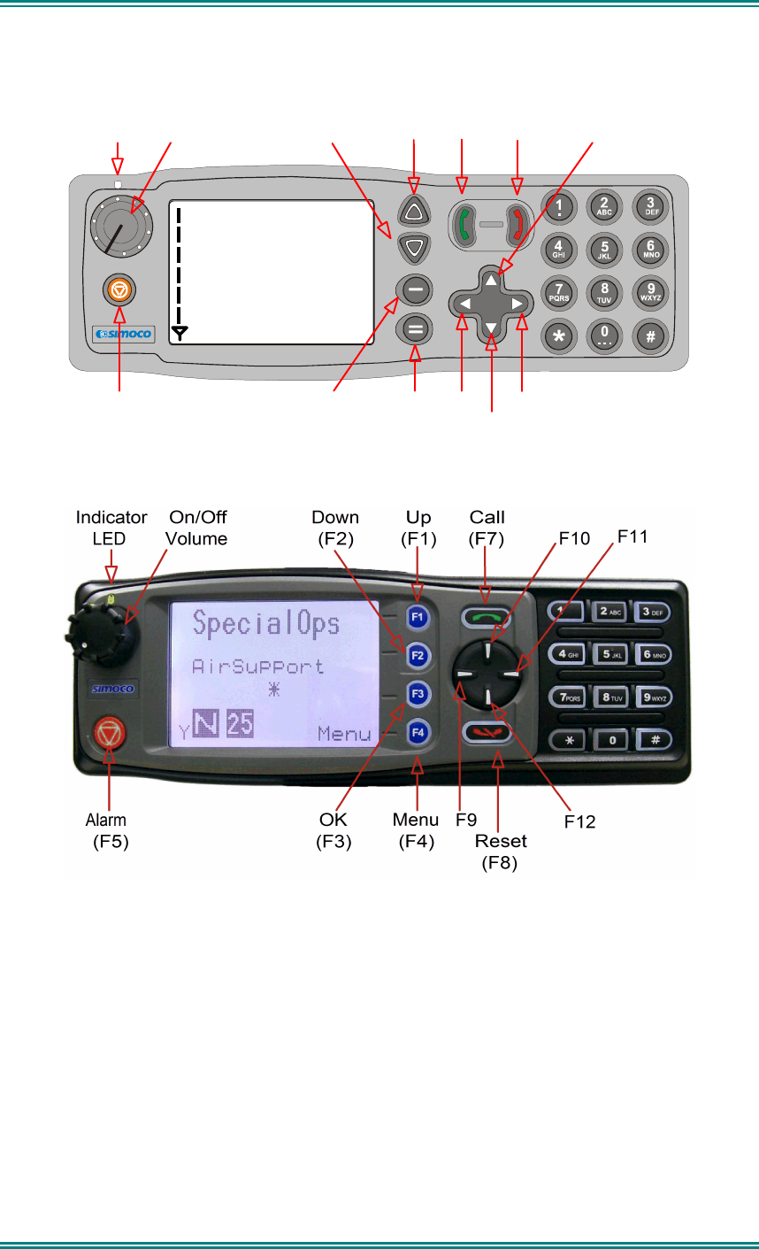
2. CONTROLS
SPECIAL OPS
ZONE 1
MENU
On/Off
Volume
Indicator
LED
Down
(F2)
Up
(F3)
Call
(F7)
Reset
(F8) F10
Alarm
(F5)
OK
(F4)
Menu
(F1)
F9
F12
F11
Figure 1 – SRM9030 Control Head
Figure 2 -SRM9030 plus Control Head
The SRM9030 Control Head has the following features:
• 11 programmable direct function Buttons
• 10 additional indirect Function Buttons (keys 0-9)
• 1000 Channels
• 40 Zones
• 250 Channels per zone
• LCD 102x64 graphic display. 8 lines of 14 characters (small font). 3 fonts, small
medium and large. Context based soft menu labels.
• LED indicator
SRM9030-P25 RADIO – OPERATING INSTRUCTIONS
© ComGroup Australia 2010 page 8 TNM-U-E-0094 Issue 1.2
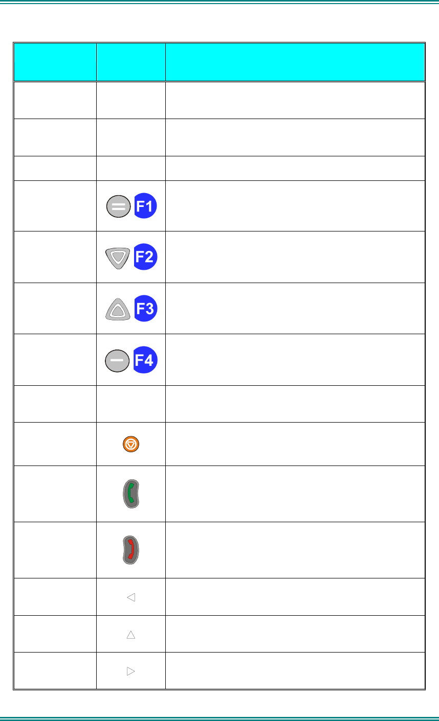
SRM9030 Key Label
9030/9030plus
Function
Power On/Off
To turn the radio on, press and hold the volume knob
for about 1 second. To turn the radio off, press and
hold the volume knob until the long tone sounds.
PTT
Push-to-Talk. Hold the microphone about 10cm from
the mouth. Press and hold the PTT switch and speak.
Release to listen.
Volume Turn the volume knob clockwise to increase volume
and anti-clockwise to reduce volume.
Function Key F1
Programmable Function key.
Default – Menu Select.
Function Key F2
Programmable Function key.
Default – Channel Down.
Function Key F3
Programmable Function key.
Default – Channel Up.
Function Key F4
Programmable Function key.
Default – OK.
Function Key F6
Programmable Function key. Located on Microphone.
Function Key F5
Programmable Function key.
Default – Alarm.
Function Key F7
Programmable Function key.
Default – Call
Function Key F8
Programmable Function key.
Default – Reset / Cancel.
Function Key F9
Programmable Function key.
Function Key
F10
Programmable Function key.
Function Key
F11
Programmable Function key.

SRM9030-P25 RADIO – OPERATING INSTRUCTIONS
© ComGroup Australia 2010 page 9 TNM-U-E-0094 Issue 1.2
SRM9030 Key Label
9030/9030plus
Function
Function Key
F12
Programmable Function key.
Keypad
1 2 3
4 5 6
7 8 9
* 0 #
Keypad can be used to select a Channel or Special
Function.
E.g. 12# will select channel 12.
Indicator LED Function
Green
Green LED when receiving a signal.
Red
Red LED when the radio is transmitting.

SRM9030-P25 RADIO – OPERATING INSTRUCTIONS
© ComGroup Australia 2010 page 10 TNM-U-E-0094 Issue 1.2
3.
MENU SYSTEM
This section details the operation of the menu system for the SRM9030-P25.
The SRM9030 has a menu system that is configurable by the FPP. The FPP has a pool of
menu entries that can be applied as required in the order required. In simple configurations,
no menu can be programmed, if required. See Figure 5 for example menu.
Pressing the “M” key from the top-level channel screen enters the menu system. This key
has a soft menu label alongside it titled “MENU”. The soft key above “MENU” is generally
the accept or “OK” key.
Y
SPECIAL OPS
Zone 5
OK
MENU
The menus possible are:
•
Zone
(usually the first menu, as often accessed)
•
Squelch
•
Mute Adjust
(FM)
/
Monitor
(Digital)
•
Phonebook
•
Phonebook Edit
•
User Options
•
Contrast
•
Alert Volume
•
Radio Info
•
Mode
•
RSSI
•
Crypto
•
Setup
•
Stored Calls
•
Messages
•
Scan Edit
•
No Menu
The presence and order of the above menu selections is determined by the FPP
configuration.
The
Setup
menu is a special case entry.
Setup
is a subgroup that can have any of the list of
menu selections assigned to it. This means that lesser used selections can be partly hidden
away under Setup subgroup if required, although still accessible.

SRM9030-P25 RADIO – OPERATING INSTRUCTIONS
© ComGroup Australia 2010 page 11 TNM-U-E-0094 Issue 1.2
The
User Options
menu group is also a menu subgroup. This subgroup usually contains
on/off functions, such as Key Beeps or Backlight
The order and presence of the
Setup
subgroup selections is determined by the FPP. For
instance
Info
,
RSSI
and
Contrast
could be placed under
Setup
.

SRM9030-P25 RADIO – OPERATING INSTRUCTIONS
© ComGroup Australia 2010 page 12 TNM-U-E-0094 Issue 1.2
3.1
M
ENU
N
AVIGATION
Pressing the “
M
” key selects
Menu
mode from the main Channel Screen. Once in menu
mode, the
▼
and
▲
keys cycle through the menus.
To exit
Menu
mode, press the “
M
” key again or the Menu timeout will exit automatically.
Generally, pressing “
M
” key while in a menu backs up to the next highest level of menu and
the “
OK
” button selects the menu screen.
The
▼
and
▲
keys are used to navigate through a list of options such as channels, or
increase/decrease a value.
When the
Menu
key is first pressed, the numeric keys become short cut keys to functions.
Numeric keys can be programmed (using FPP) with functions i.e. Scan.
To access this, you can press the “
M
” or menu key from the channel screen and then the
numeric key assigned to that function.
SRM9030-P25 RADIO – OPERATING INSTRUCTIONS
© ComGroup Australia 2010 page 13 TNM-U-E-0094 Issue 1.2
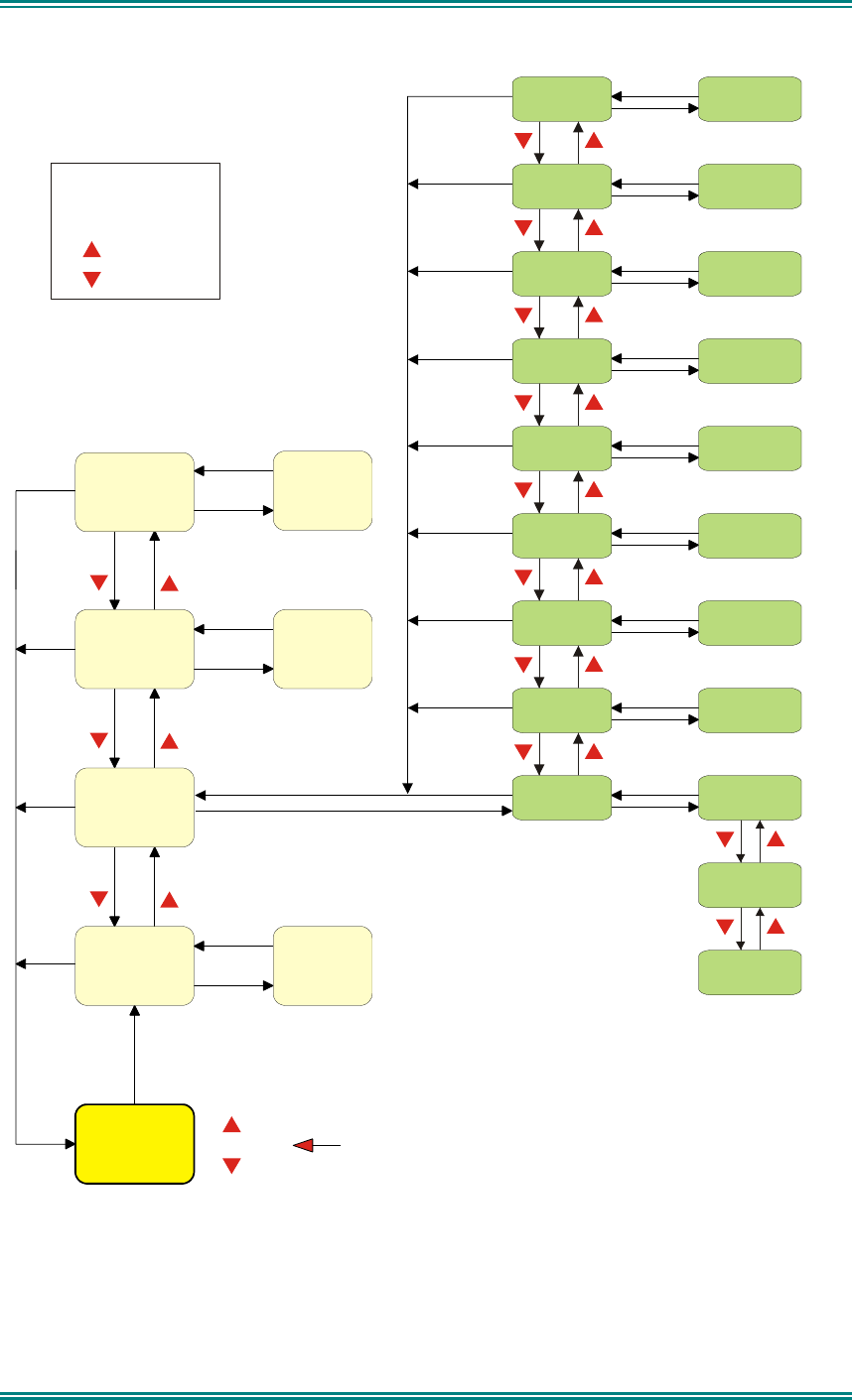
Figure 3 - Menu Navigation
Normal
Channel
Screen
Zone Select
Menu #1
Setup Menu
(Optional)
(Optional)
Menu #2
Menu #3 Menu #3
Menu #x Menu #x
Select
Zone
ENTRY POINT = Default Screen
Channel
Note:
Example Menus only shown.
P25 Conventional Menu rev1d
Other Menus may be configured with the FPP
Up Key
Down Key
Back Key
OK Key
Squelch
Mute
Adjust
SubMenu Selections
RSSI
Mode
Radio Info
Crypto Key
Alert
Volume
Contrast
User Options
Submenu
Submenu
Submenu
Submenu
Submenu
Submenu
Submenu
Submenu
Key Beeps
ON/OFF
Backlight
ON/OFF
(Other User
Menu items)
Back
OK
Menu
OK
OK
OK
OK
OK
OK
OK
OK
OK
BackBack
BackBack
BackBack
Back
Back
OK
BackBack
Back
OK
BackBack
Back
Back
OK
BackBack
Back
Back
OK
BackBack
BackBack
BackBack

SRM9030-P25 RADIO – OPERATING INSTRUCTIONS
© ComGroup Australia 2010 page 14 TNM-U-E-0094 Issue 1.2
4. MENU SCREENS
4.1 C
HANNEL
S
CREEN
Y
SPECIAL OPS
Zone 5
OK
MENU
The Channel Screen shows the current channel and allows channel selection.
The
Channel Name
(top line)
shows the text associated with the currently selected radio
channel.
The
Zone Name
(middle) shows the text associated with the currently selected radio zone.
The
RSSI Bars
(left) indicate the signal strength of the current channel.
Pressing the “
Menu”
key enters the
Menu
mode.
The lower part of the screen is reserved for icons.
Radio channels may be configured with the Field Programmer as specific frequencies or as
auto scan types. When an auto scan channel is selected, it will immediately go into scan
mode. Selecting another non-autoscan channel will stop the scan.
If a radio channel is defined as a P25 Conventional Digital Channel, it will only receive P25
digital signals.
If a radio channel is defined as an Analogue FM channel, it will receive both P25 Digital* and
Analogue FM signals.
A radio channel defined as a P25 Trunked network will automatically start searching for the
pre-programmed network, and only receive signals from that network once it has service.
* While in Analogue mode, all unencrypted digital P25 traffic will be heard regardless of NAC
or Talkgroup.
SRM9030-P25 RADIO – OPERATING INSTRUCTIONS
© ComGroup Australia 2010 page 15 TNM-U-E-0094 Issue 1.2
Y
SPECIAL OPS
Zone 5
OK
MENU
1 2 3
6
5
4
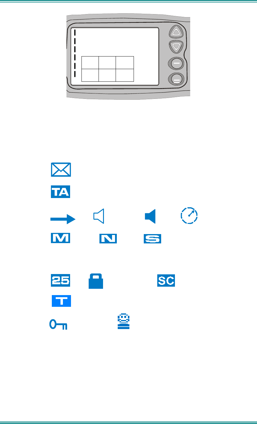
Figure 4 Icon Locations
As there are six positions for icons and displayed icons exceed this, some icons will share
the same location.
Position Icon
1
(Message)
2
(Talk Around)
3
(TX) (Other Signal) (Signal) (Scanning)
4
(Monitor) (Normal) (Selective)
4
C
(Connecting)
!
(Connect Fail)
5
(P25) (Digital Encrypted ) ( Scrambler)
5
(Trunking)
6
(Locked Keypad) (Individual Call)
SRM9030-P25 RADIO – OPERATING INSTRUCTIONS
© ComGroup Australia 2010 page 16 TNM-U-E-0094 Issue 1.2
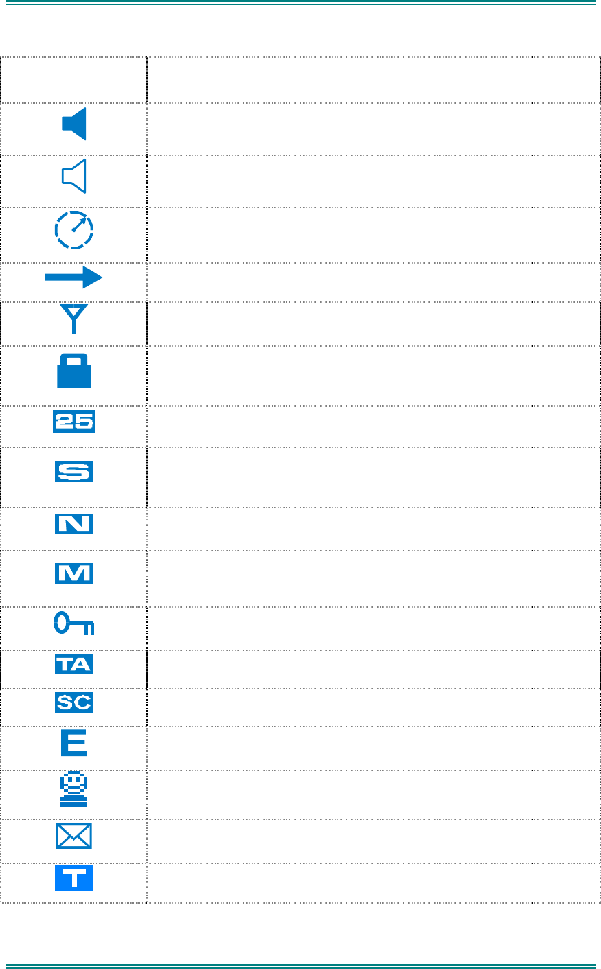
ICONS
INDICATION
A filled speaker indicates that a signal is present and the audio can
be heard from the speaker.
The outline speaker icon indicates that a signal is present and the
radio is muted. This could be another user group, for instance.
Scan Indicator. When radio is on a scan channel and scanning, the
arrow will rotate.
Transmit Indicator.
Received Signal Strength Indication (RSSI). A stronger signal will
display more bars above the “antenna” icon
Encryption Indicator. The icon is shown when the selected channel is
programmed for encryption. If an unencrypted signal is received, the
icon will be not be displayed.
25 = Digital Mode Indicator.
Selective Mute. Only radio signals specifically directed to the user or
the channel’s defined talkgroup will be heard on the speaker.
Normal Mute. Only radio signals from the users own network will be
heard on the speaker.
Monitor. All P25 digital radio signals on the channel will be heard.
All keys except PTT, or any function assigned as Alarm, will be
disabled. Press the OK key for 2 seconds to unlock all keys.
Talk Around enabled indicator. When shown, Talk Around is active.
Scrambler indicator. (analogue only)
Emergency mode. Blinking icon indicates that the emergency button
has been pressed.
Individual Addressing Mode. When shown, the radio will transmit to
an individual address instead of a talkgroup
Envelope icon. Indicates that a message(s) stored if icon steady,
icon flashes if unread message(s) stored.
Trunking Icon. Displayed when the radio is in Trunking Mode.

SRM9030-P25 RADIO – OPERATING INSTRUCTIONS
© ComGroup Australia 2010 page 17 TNM-U-E-0094 Issue 1.2
C
Connecting icon. Shown when a text message is being sent and the
connection is in progress.
!
Connection Fail icon. Shown when a text message transmission has
failed.
*
Radio has stopped on a scan channel.
SRM9030-P25 RADIO – OPERATING INSTRUCTIONS
© ComGroup Australia 2010 page 18 TNM-U-E-0094 Issue 1.2
4.2 M
ENUS
The menu structure on the SRM9000 is configurable using the Field Programmer. A system
administrator usually tailors the order and presence of the menu options to specific customer
requirements.
This section will describe all the possible menus.
Normally the menus are divided into two menu lists.
These are normally the Main menu list and the Setup menu list.
In the default configuration, the Main menu contains the Zone screen and a Setup screen.
This allows access to the second “Setup” menu level.
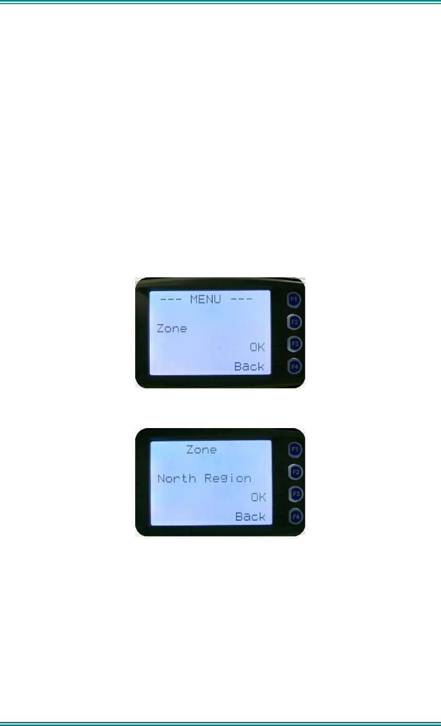
4.2.1 Zone Menu
The Zone Screen is used for changing Zones. A Zone is normally defined as a group of radio
channels with a common operational role.
When the “
Zone
” menu option is displayed, press the “
OK
” button to enter the “
Zone
“ select
screen.
Once the “
Zone
” menu appears, press the ▼ and ▲ keys to choose the required Zone.
Press the “
OK
” key to select the required Zone. The radio will return to the channel screen
and select the first channel in the new Zone.
Direct access to the “
Zone
” menu from other screens can also be programmed to one of the
function buttons with the Field Programmer.
SRM9030-P25 RADIO – OPERATING INSTRUCTIONS
© ComGroup Australia 2010 page 19 TNM-U-E-0094 Issue 1.2
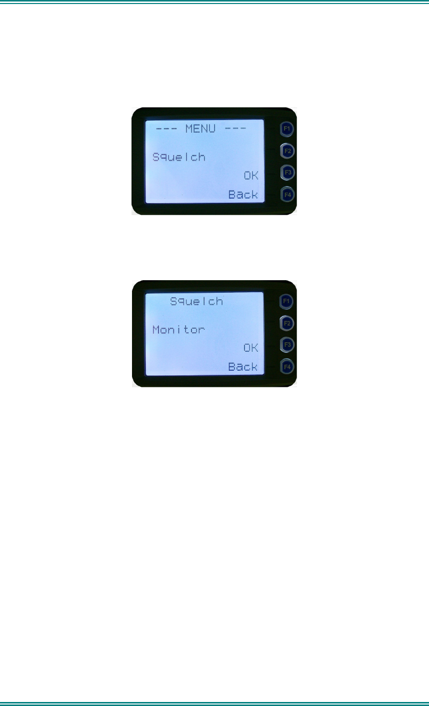
4.2.2 Squelch
This menu allows the channel’s default squelch mode to be modified.
If the selected channel is changed or the radio is switched off, the channel’s default squelch
setting will be restored.
Press the “
OK
” key for the “
Squelch
” Menu.
P25 Squelch Screen
For a P25 digital channel, pressing the
▼
and
▲
keys will allow selection of either
Monitor
,
Normal
or
Selective
squelch mode.
For an analogue channel, pressing the
▼
and
▲
keys will allow selection of either
Monitor
or
Normal
squelch mode.
Digital Channel Monitor Mode:
The radio will receive any decryptable or clear P25 digital voice signals. The Network Access
Code (NAC) is not checked. An “
M
” icon on the display indicates monitor mode.
Digital Channel
Normal Mode:
When
Normal
squelch is selected, the radio will receive all decryptable or clear digital
transmissions with the correct NAC. It does not check the Talk Group or Unit ID. An “
N
”
icon on the display indicates normal squelch.
Digital Channel
Selective Mode
If
Selective
squelch is chosen, the radio will only receive decryptable or clear digital
transmissions with the correct NAC and Talk Group ID (TGID) or correct NAC and Unit ID.
An “
S
” icon indicates selective squelch.

SRM9030-P25 RADIO – OPERATING INSTRUCTIONS
© ComGroup Australia 2010 page 20 TNM-U-E-0094 Issue 1.2
Analogue Channel Monitor Mode:
The radio will receive any Analogue voice or P25 digital signals. Digital NAC or Analogue
CTCSS is not checked. An “
M
” icon indicates monitor.
Analogue Channel
Normal Mode:
When
normal
mute is selected, the radio will receive correctly addressed Analogue radio
transmissions and all decryptable or clear digital transmissions. An “
N
” icon indicates
Normal.
Pressing the “
OK
” key returns to the main channel screen.
Pressing the “
Back
” or “
Menu
” key returns to the next highest menu level

SRM9030-P25 RADIO – OPERATING INSTRUCTIONS
© ComGroup Australia 2010 page 21 TNM-U-E-0094 Issue 1.2
4.2.3 Mute Adjust
From the menu list, step through the menu options with the
▼
and
▲
keys until the “
Mute
Adjust
” menu is displayed.
Press the “
OK
” key for the Mute adjustment screen.
Analogue Mute Screen
The mute adjustment will be applied to all the radio’s analogue channels.
Use the
▼
and
▲
keys to adjust the mute threshold. A numeric value of the present mute
level is shown.
The “
OK
” key returns to the default channel screen with the selected mute setting.
It is recommended that the default mute setting of 4 is used. The SRM9000 series radios
have a carrier noise mute and this means the mute will open at the point where an analogue
signal is sufficiently noise free to be intelligible with a setting of 4.
Other settings are as follows:
0 no muting
4 normal setting,
8 will only hear reasonably strong signals
15 will only hear very strong signals.
Pressing the “
OK
” key will exit to the Channel Screen with the selected mute setting.
Direct access to the “
Mute Adjust
” screen from other screens can also be programmed to
one of the function buttons with the Field Programmer.

SRM9030-P25 RADIO – OPERATING INSTRUCTIONS
© ComGroup Australia 2010 page 22 TNM-U-E-0094 Issue 1.2
4.2.4 Phonebook Menu
When “
Phone Book
” is selected from the menu screen, the Phone Book Screen is shown.
From this screen, it is possible to view the of all phone entries in the phone book.
The second line shows the name of the selected phone book entry.
The third line shows the unit identifier of the phone book entry. This is the P25 ID that the
radio will call.
The fourth line shows the IP address associated with the phone book entry. IP addresses
are used for data calls.
Phone book entries may be selected with the
▼
and
▲
keys.
A “Reset” function key press (if configured) takes the radio back to the default screen display.
When the “
Back
” key or “
Menu
” is pressed, the radio returns to the Menu screen.
4.2.4.1 Making an Individual Call
When “
PTT
” key is pressed:
• The radio is changed to individual call mode (individual call to the unit identifier of the
selected phone entry). The individual call icon is displayed.
• If the radio is already in individual call mode addressed to a different unit, the
destination unit ID shall be replaced by that of the newly selected phone entry.
• The radio will remain in individual call mode until the inactivity timeout has elapsed,
ie. No PTT or signal received for the Field Programmer set time period (typically 10
seconds).
• The radio will return to the default screen.
4.2.4.2 Making an Individual Call with Call Alert
When the
“OK”
key is pressed with the Phone Book entry displayed:
A Call Alert is sent to the displayed ID.
The called radio will sound a Call Alert.
SRM9030-P25 RADIO – OPERATING INSTRUCTIONS
© ComGroup Australia 2010 page 23 TNM-U-E-0094 Issue 1.2
4.2.5 Phonebook Edit Menu
The Phone Book can be modified so that new entries can be added and existing entries can
be modified or removed from the phone book.
Phone book entries may be Individual Addresses, Telephone numbers or Talk Groups.
Changes to the phone book are permanent.
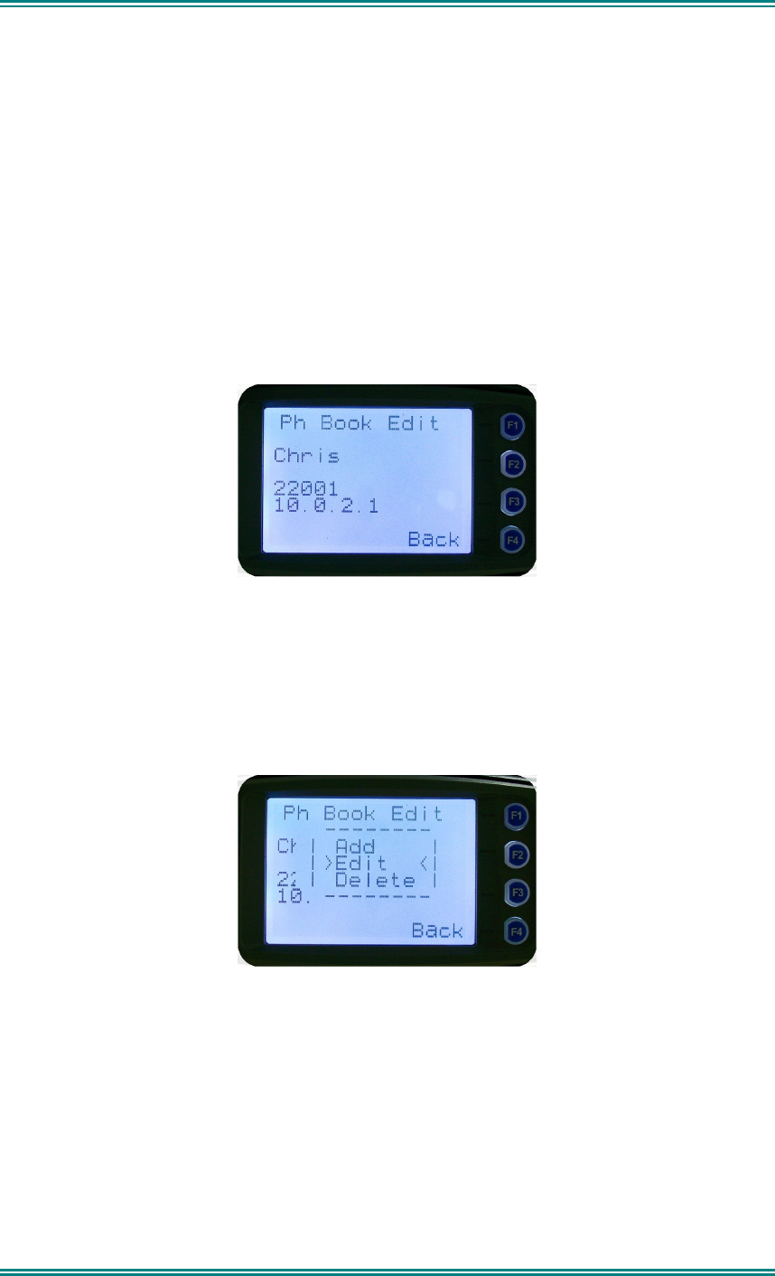
4.2.5.1 Phonebook Edit Default Screen
When “
Phone Book Edit
” is selected from the menu screen, the radio displays the Phone
Book Edit Screen.
From this screen, an entry can be chosen using the
▼
and
▲
keys.
The displayed information is the same as the Phone Book Screen display.
A
“Reset”
function key press (if configured) takes the radio back to the default screen
display.
If the “
Back
” key or “
Menu
” key is pressed, the radio returns to the MENU screen.
If the “
OK
” key is pressed, the “
Phone Book Edit
” pop-up menu is displayed.
4.2.5.2 Phone Book Edit Pop-up menu
The pop-up items are:
•
Add:
to add a new phone entry
•
Edit:
to edit (modify) the selected phone entry.
•
Delete:
to delete the currently selected phone entry.
The selection is made with the
▼
and
▲
keys.
The “
Menu
” or “
Back
” key takes the radio back to the Phone Book Edit Default Screen.
SRM9030-P25 RADIO – OPERATING INSTRUCTIONS
© ComGroup Australia 2010 page 24 TNM-U-E-0094 Issue 1.2
A “
Reset”
function key press (if configured) takes the radio back to the default screen
display.
If “
Delete
” is selected, pressing “
OK
” removes the selected phone entry from the phone book
and takes the radio back to the default screen display.
If “
Add
” is selected, pressing “
OK
” takes the radio to the Add New Entry sub-menu.
If “
Edit
” is selected, pressing “
OK
” takes the radio to the Edit Phone Entry sub-menu.
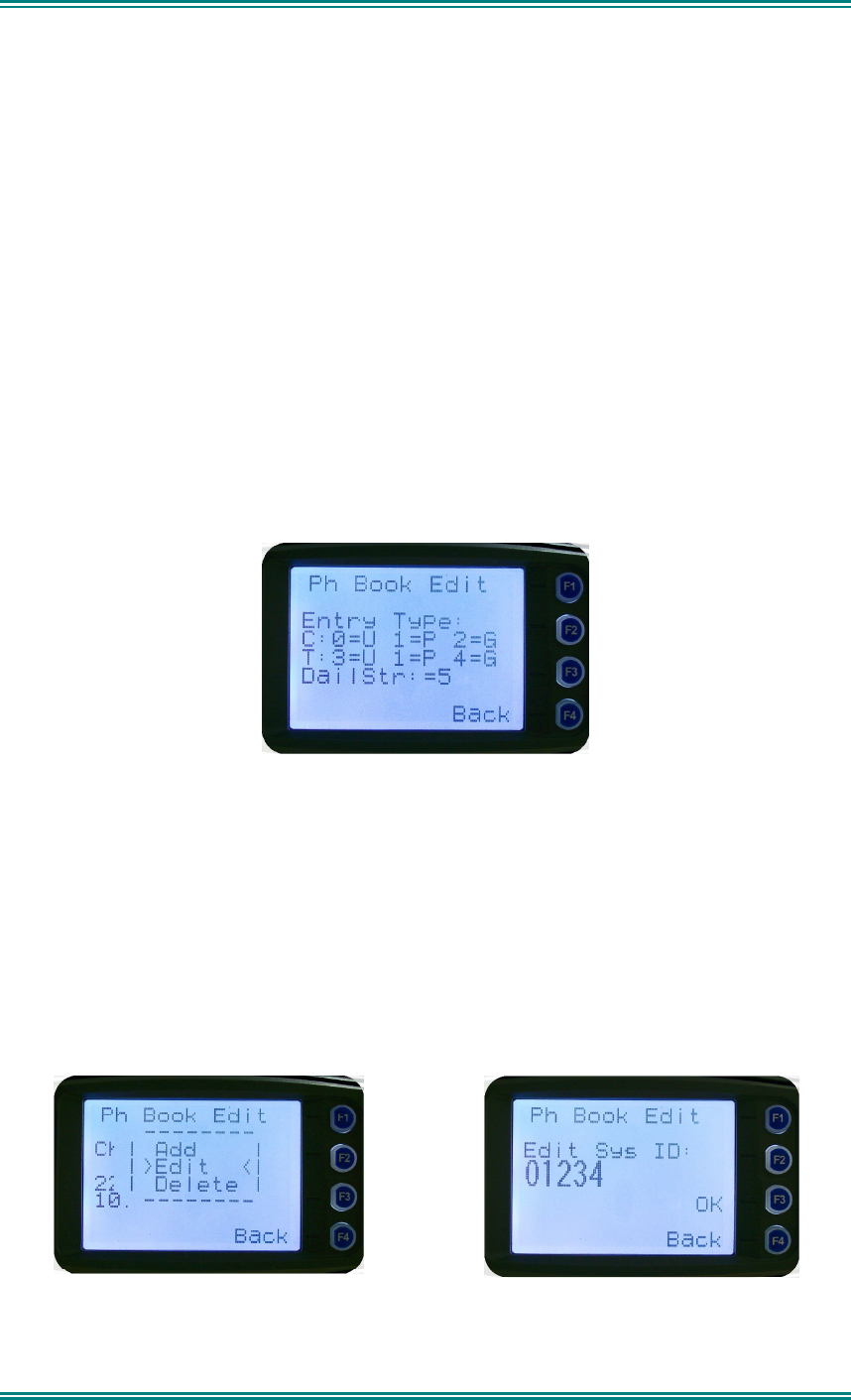
4.2.5.3 Phone Book Edit – Add New Phone Entry
The first edit screen is the entry type screen. There are 6 possible types of Phone Book
entries. These are:
Conv.Unit ID (Option 0) Conv.PSTN (Option 1) Conv.Group (Option 2)
Trunk Unit ID (Option 3) Trunk PSTN (Option 1) Trunk Group (Option 4)
Dialstring (Option 5)
Make the selection 0 – 5 and select OK.
From here, enter the System ID value as described in the Phonebook Edit section.
4.2.5.4 Phonebook Edit
This selection is used to edit an existing phone book entry. The operation is similar to adding
a phonebook entry in previous section.
In this example, editing a P25 Trunked ID is shown. It is also possible to edit a P25
Conventional ID and a P25 Group Entry.
The first step is to edit the System ID.
Upon entering this screen, the current trunked System ID of the selected entry is displayed.
SRM9030-P25 RADIO – OPERATING INSTRUCTIONS
© ComGroup Australia 2010 page 25 TNM-U-E-0094 Issue 1.2
The System ID entry can then be changed using the numeric digits and
▼
key as a
destructive backspace.
Once the New System ID is entered, press “
OK
” key to move on to the next sub-menu
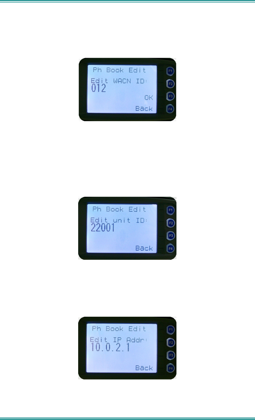
screen to edit the WACN ID, if required.
Upon entering this screen, the current WACN ID of the selected entry is displayed.
The WACN ID entry can then be changed using the numeric digits and
▼
key as a
destructive backspace.
If there is no change for the WACN ID, press “
OK
” key to move on to the next sub-menu
screen to edit the name.
The next step is to edit the Unit ID, if required.
Upon entering this screen, the current Unit ID of the selected entry is displayed.
The entry can then be changed using the numeric digits and
▼
key as a destructive
backspace.
If there is no change for the Unit ID, press “
OK
” key to edit the IP address, if required.
Upon entering this screen, the current IP address of the selected phone entry is displayed.

SRM9030-P25 RADIO – OPERATING INSTRUCTIONS
© ComGroup Australia 2010 page 26 TNM-U-E-0094 Issue 1.2
The IP address can then be changed using the numeric digits and
▼
and
▲
key to move the
cursor with
▼
function key as a destructive backspace. The “
#
” key is used to enter a “.”.
If there is no change for the IP address, press “
OK
” key and move on to the next sub-menu
screen to edit the name.
Upon entering this screen, the current name of the selected phone entry is displayed.
The name entry can then be changed using the numeric digits and
▼
and
▲
key to move the
cursor with
Reset
function key to delete.
If there is no change for the name, press “
OK
” key to complete the editing on the phone
entry. The phone entry will be modified in the radio, and the radio will return to the default
screen.

SRM9030-P25 RADIO – OPERATING INSTRUCTIONS
© ComGroup Australia 2010 page 27 TNM-U-E-0094 Issue 1.2
4.2.6 User Options
The “
User Options
” menu provides access to a list of Functions that may be toggled on or
off. Up to 10 functions may be defined in this menu by the FPP programmer.
Press the “
OK
” key for the “
User Options
” screen.
When the Function is selected, the function can be toggled ON or OFF with the “
OK
” key.
The
▼
and
▲
keys are used to select the other functions.
Pressing the “
Back
“ or “
Menu
” key saves all the function settings and returns to the next
highest menu level.
Toggle functions include Key Beeps, Backlight, Talk-Around, Analogue Scrambler and Low
Power Override.
These functions can also be assigned directly to the radio’s function buttons, if required.
SRM9030-P25 RADIO – OPERATING INSTRUCTIONS
© ComGroup Australia 2010 page 28 TNM-U-E-0094 Issue 1.2
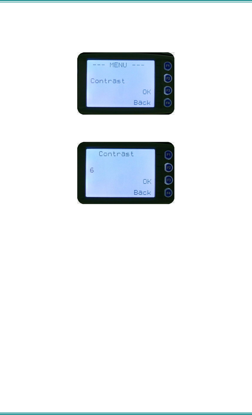
4.2.7 Contrast
This menu allows the screen’s contrast setting to be changed.
Press the “
OK
” key for the “
Contrast
” adjustment screen
When the “
Contrast
” menu is selected, the contrast can be adjusted with the
▼
and
▲
keys.
The numeric value of the Contrast is displayed.
Pressing the “
OK
” key returns to the main channel screen.
Pressing the Back or “
Menu
” key returns to the next highest menu level.
SRM9030-P25 RADIO – OPERATING INSTRUCTIONS
© ComGroup Australia 2010 page 29 TNM-U-E-0094 Issue 1.2
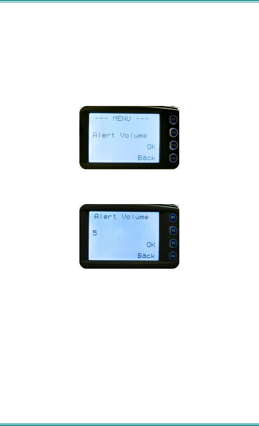
4.2.8 Alert Volume
This Screen allows you to set the level of the relative Alert Volume level in relation to the
current Volume setting. The level can be set in 62 steps over the range -31 to +31, with 0
being about the same as the voice level. For example, if the alert volume is set to –6, it will
be softer than received voice on the radio.
From the Settings Sub Menu, step through the menu options with the
▼
and
▲
keys until the
Alert menu is displayed.
Press the “
OK
” key for the “
Alert Volume
” adjustment screen
Use the
▼
and
▲
keys to change the relative alert volume level. The beep will sound at the
indicated level each time the setting is changed.
Press “
OK
” to accept the setting and return to the Channel Screen.
Pressing the “
Menu”
key will exit back to the setup menu.
Note: A minimum Alert Level may be set by the FPP to ensure that the Alerts can always be
heard from the speaker.
SRM9030-P25 RADIO – OPERATING INSTRUCTIONS
© ComGroup Australia 2010 page 30 TNM-U-E-0094 Issue 1.2
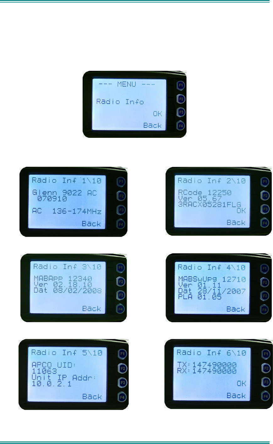
4.2.9 Radio Information
These screens display information that identifies the Field Programmer File description,
Radio ID, Serial Number, Software Version and IP Address.
From the Settings Sub Menu, step through the menu options with the
▼
and
▲
keys until the
Radio Info menu is displayed.
Press the “
OK
” key for the “
Radio Info
” Screen.
The
▼
and
▲
keys select the following information pages:
Description, P25 Conv. Unit ID and Radio Band
Radio Software Version and Serial Number
Application Software Version and Date
Application Upgrade Version, Date and PLA
P25 Radio Unit Trunked ID and IP Address
P25 Trunked SysID, WACN, GID and UID
SRM9030-P25 RADIO – OPERATING INSTRUCTIONS
© ComGroup Australia 2010 page 31 TNM-U-E-0094 Issue 1.2
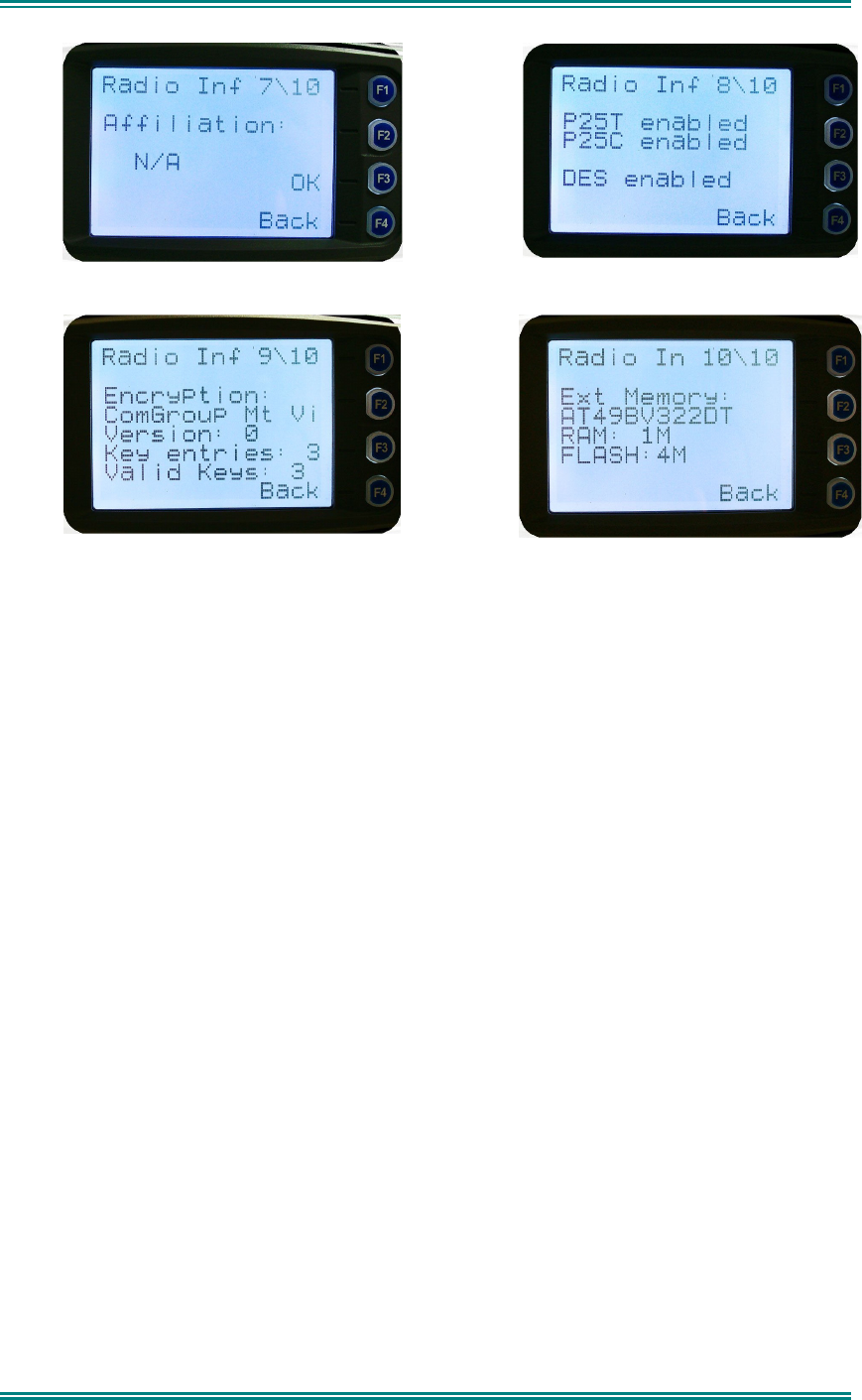
Feature Authorisation Enables
Encryption Status
Encryption Summary
External Application Memory Status
The “
Radio Info
“ screens are read-only screens. Press “
OK
” to return to the Channel
Screen.
SRM9030-P25 RADIO – OPERATING INSTRUCTIONS
© ComGroup Australia 2010 page 32 TNM-U-E-0094 Issue 1.2
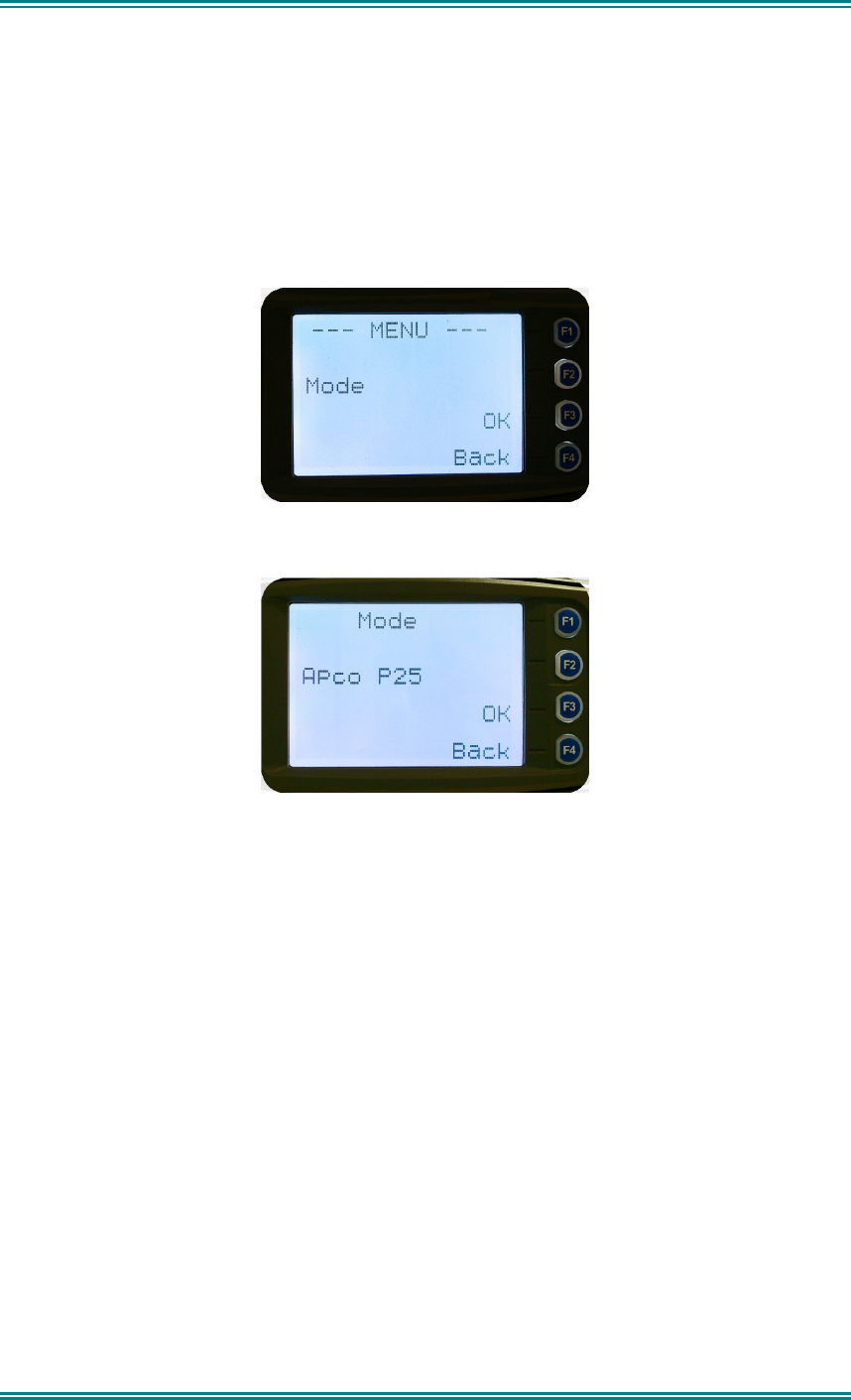
4.2.10 Mode Menu
The mode menu is used for changing from one radio to another, such as PMR/LMR mode to
P25 or MPT1327 trunking.
From the Channel Screen, select menu mode with the “
Menu
” key and step through the
menus with the
▼
and
▲
keys until the “Mode” menu is reached.
Press “OK” to select the Mode menu.
From the “
Mode
” menu, use the ▼ and
▲
keys to select the required operating mode, such
as Apco P25, PMR or MPT Trunking. While the required mode is displayed, press OK to
select that operating mode. The radio will then display the default screen for that mode.
Keypad shortcuts can be used to change modes from the keypad.
• PMR (*60#)
• P25 (*80#)
• MPT Network 1 (*71#)
• MPT Network 2 (*72#)