Simoco Wireless Solutions SRMA9000AC VHF MOBILE TRANSCEIVER User Manual USERS MANUAL B
Simoco Australasia Pty Ltd VHF MOBILE TRANSCEIVER USERS MANUAL B
Contents
- 1. USERS MANUAL A
- 2. USERS MANUAL B
USERS MANUAL B
SRM9030-P25 RADIO – OPERATING INSTRUCTIONS
© ComGroup Australia 2010 page 33 TNM-U-E-0094 Issue 1.2
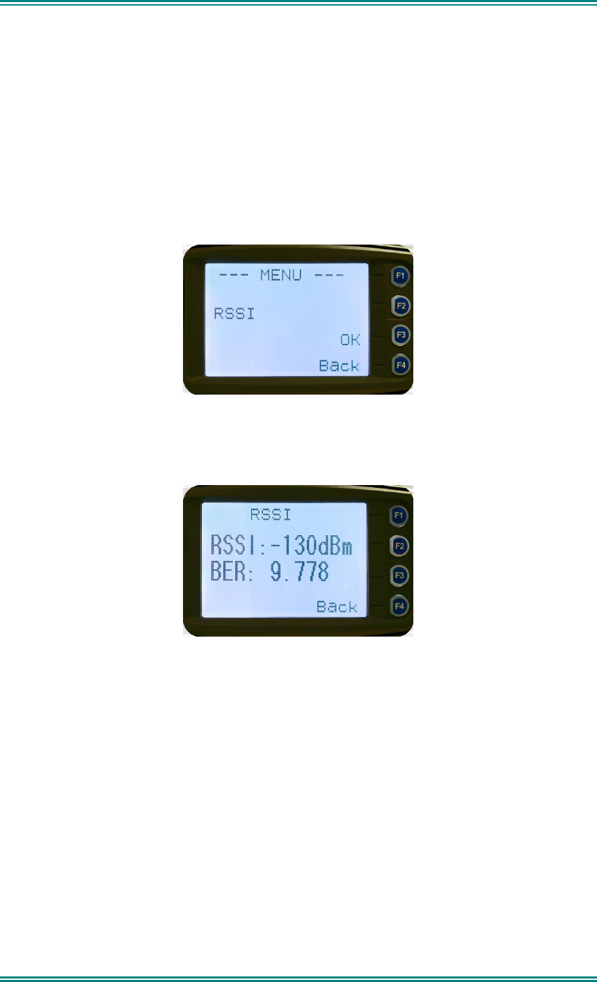
4.2.11 RSSI (Received Signal Strength Indication)
This screen displays the received signal strength in dBm. The reading is typically accurate
within +/- 2 dBm between -120 and -80dBm, if the radio has been correctly calibrated. For
example, -90dBm is a strong signal and –120dBm is no signal.
The screen also shows the Bit Error Rate (BER) on digital channels. RSSI and BER are
typically used to indicate signal quality.
From the Settings Sub Menu, step through the menu options with the
▼
and
▲
keys until the
“
RSSI
” menu is displayed.
Press the “
OK”
key for the “
RSSI
“ screen
If a Digital channel is selected BER will be displayed.
The RSSI/BER will be displayed until either the “
Menu
” key is pressed to return to the next
highest menu level or the “
OK
” key is pressed which will return to the main channel menu.
A lower RSSI value indicates a stronger signal, ie. –80dBm is a stronger signal than
–100dBm.
SRM9030-P25 RADIO – OPERATING INSTRUCTIONS
© ComGroup Australia 2010 page 34 TNM-U-E-0094 Issue 1.2
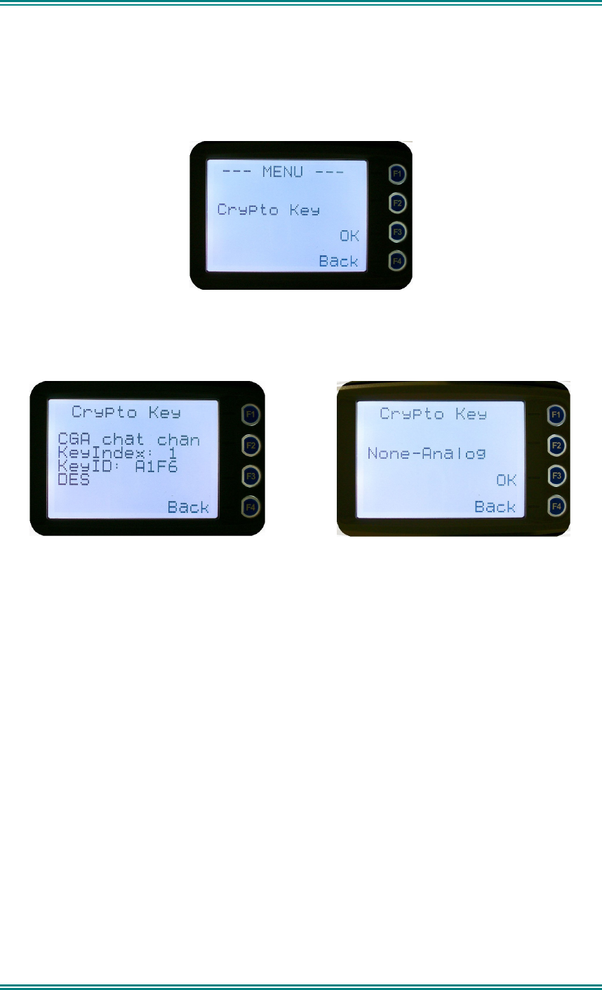
4.2.12 Crypto
This menu allows the digital channel’s default transmit encryption key to be modified. The
current selected digital channel has encryption enabled if the padlock symbol is displayed.
Press the “
OK
” key for the “
Crypto Key
” menu.
Digital Analogue
If an Analogue channel is selected, a warning message will display “None-Analog
When the Crypto menu is selected, the digital channel’s Encryption Key ID can be changed
with the
▼
and
▲
keys.
The key name and the key identifier (1-32) for the selected channel is displayed.
If the selected channel is changed or the radio is switched off, the channel’s default
encryption key will be restored.
Pressing the “
OK
” key returns to the main channel screen.
Pressing the “
Back
” or “
Menu
” key returns to the next highest menu level.

SRM9030-P25 RADIO – OPERATING INSTRUCTIONS
© ComGroup Australia 2010 page 35 TNM-U-E-0094 Issue 1.2
4.2.13 Setup Menu
The screens in the Setup sub-menus allow the radio operator to edit/modify the operation of
some of the general functions of the radio.
Once the
Menu
key is pressed from the “Channel” screen, the
▼
and
▲
keys cycle through
the available “Main” menus. Once the “Setup” menu appears, press the “
OK”
key to select
it.
The
▼
and
▲
keys are then used to scroll through the setup menus.
The Setup menu structure may include, for example:
•
Alert Volume,
•
Contrast,
•
RSSI (Received Signal Strength Indication),
•
Info (Radio software and hardware information),
•
Crypto (Select Transmit Encryption Key),
•
Squelch,
•
Mute Adjust or
•
User Options
SRM9030-P25 RADIO – OPERATING INSTRUCTIONS
© ComGroup Australia 2010 page 36 TNM-U-E-0094 Issue 1.2
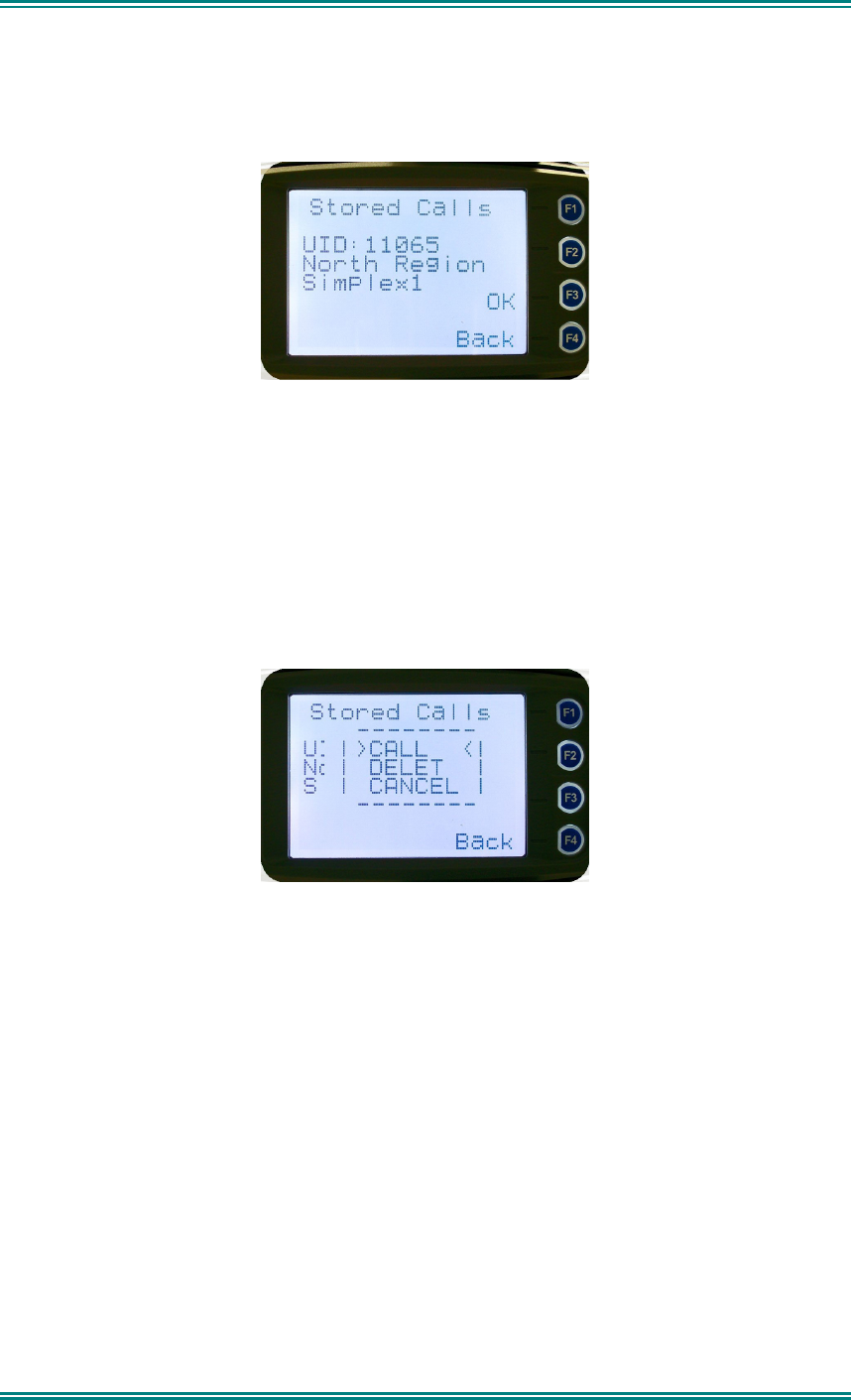
4.2.14 Stored Calls
This screen displays the received individual call records one by one, starting with the most
recently received call record.
Either the name of the caller from the phone book or the user ID is displayed if the ID is not
known to the phone book. If stored calls are empty, NO RECORD is displayed.
The
▼
and
▲
keys can be used to step through the stored calls. An error beep will sound if
there are no more call records.
A “
Reset
” function key press (if configured), takes the radio back to the default screen
display.
The “
Menu
” or “
Back
” key returns to Menu screen. When “
OK
” key is pressed, a pop up
menu is displayed so that the message can be deleted or party called back.
The selections are:
•
DELETE
– to delete the call record.
•
CALL
– to call back the caller (set individual call to the caller)
•
CANCEL
– to cancel the action selection.
The selection is made with the
▼
and
▲
keys.
The “
Menu
” or “
Back
” key returns to Stored Calls screen”.
A “Reset” function key press (if configured) takes the radio back to the default screen display.
If “
DELETE
” is selected, pressing “
OK
” removes the selected call record (being viewed) from
the list. The radio returns to the Stored Calls Screen with the next record being displayed.
If “
CANCEL
” is selected, the
Stored Calls
screen is displayed.
If “
CALL
” is selected, pressing “
OK
” sets the radio to individual calling mode with the ID of
the stored call. A subsequent PTT within the configured time interval will send an individual
call to the ID of the stored call.
SRM9030-P25 RADIO – OPERATING INSTRUCTIONS
© ComGroup Australia 2010 page 37 TNM-U-E-0094 Issue 1.2
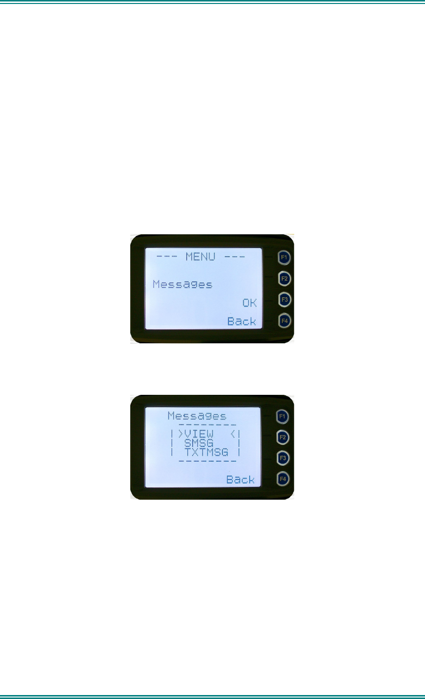
4.2.15 Messages
A radio unit can receive and transmit predefined short messages and text messages with
another radio unit on a digital channel (P25 conventional only).
Messages received are stored in radio memory. They can be viewed and deleted as
required.
If there are unread messages stored in the radio, the envelope icon on the default screen will
flash.
If there are messages in the radio that have all been read, a steady envelope icon is shown
on the default screen.
If there are no messages in the radio, the envelope icon will not appear on the default
screen.
To view/delete/send messages, go to the Menu selection and choose the “
Messages
” menu.
When “Messages” is selected from the menu screen with “OK”, a pop-up screen will
appear.
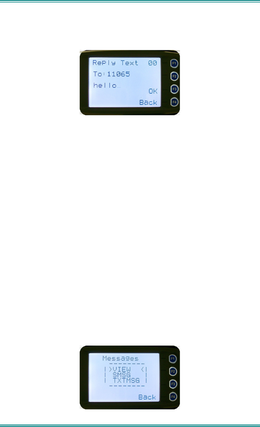
4.2.15.1 Messages Selection Pop-Up Menu
The pop-up selections are:
•
VIEW
: View received messages.
•
SMSG:
Short Message. The radio can be programmed with a list of predefined
messages. Choosing
SMSG
shows a list of predefined messages, which can be
sent as a short message to another radio unit. Only applicable when a digital
channel is selected.
•
TXTMSG:
Text message. Enters the text message edit and send sub-menus. Only
applicable when a digital channel is selected.
Options are selected with the
▼
and
▲
keys.
SRM9030-P25 RADIO – OPERATING INSTRUCTIONS
© ComGroup Australia 2010 page 38 TNM-U-E-0094 Issue 1.2
Pressing “
Menu
” or “
Back
” keys takes the radio back to the Menu screen.
A “
Reset
” function key press (if configured) takes the radio back to the default screen
display.
If “
VIEW
” is selected, pressing “
OK
” shows the Message View screen.
If “
SMSG
” is selected, pressing “
OK
” shows the Short Message screen only for a digital
channel, otherwise an error beep will sound.
If “
TXTMSG
” is selected, pressing “
OK
” shows the Edit Text Message screen only for a
digital channel, otherwise an error beep will sound.
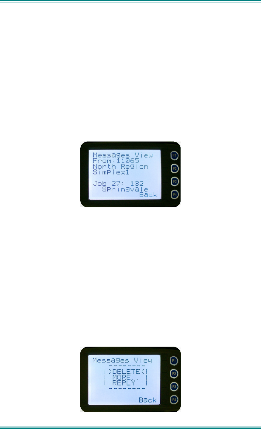
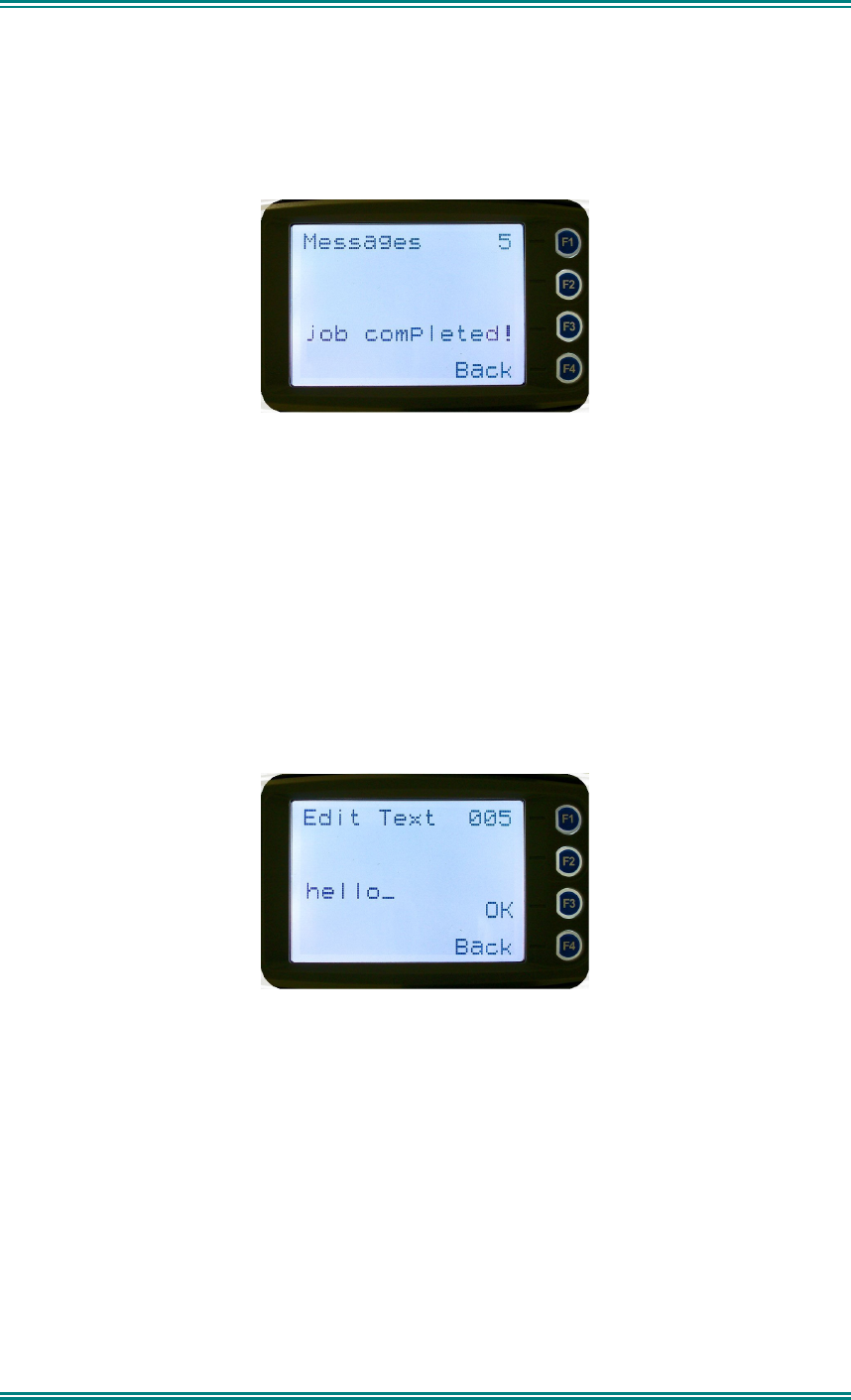
4.2.15.2 View Received Messages Screen
Received messages (both short messages and text messages) can be viewed from this
screen.
This screen displays the received messages one by one, starting with the most recent
received message.
The information displayed for each message includes the sender ID (S Unit) and the first 2
lines of the received message in text string.
If no messages are stored, “
NO RECORD
” is displayed.
To step through other stored messages, use the
▼
and
▲
keys. If there is no further
message stored, an error beep will sound.
A “
Reset
” function key press (if configured) takes the radio back to the default screen
display.
If the “
Back
” or “
Menu
” key is pressed, the radio will return to the Messages Selection pop-
up Menu.
Pressing the “
OK
” key displays the Message View pop-up menu with further options.
.
SRM9030-P25 RADIO – OPERATING INSTRUCTIONS
© ComGroup Australia 2010 page 39 TNM-U-E-0094 Issue 1.2
4.2.15.3 Message View Pop-Up Menu
The Message View pop-up allows the following options:
•
Delete
–deletes the current received message.
•
More
– to view the full (entire) message.
•
Reply
– to select the method of replying to the selected message.
Selection is performed using the
▼
and
▲
keys.
Pressing the “
Menu
” or “
Back
” key takes the radio back to the “
Messages View
” Screen.
A “Reset” function key press (if configured) takes the radio back to the default screen display.
If “
Delete
” is selected, pressing “
OK
” will remove the current selected message from the
radio. The radio will return to the “
Messages View
” screen with the next message being
selected and displayed.
If “
More
” is selected, pressing “
OK
” will display the full message.
If “
Reply
” is selected, pressing “
OK
” will display the “
Message Reply”
pop-up screen.
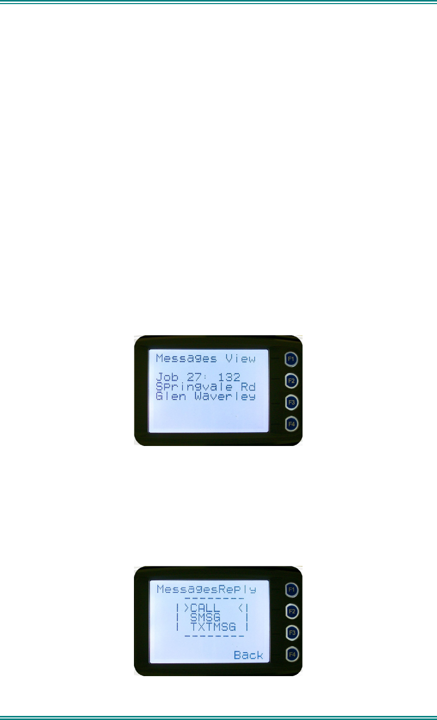
4.2.15.4 More Message View Screen
This Screen displays the selected message in full scale – 6 lines of message text per
page of the selected message.
If a message exceeds a screen, the
▼
and
▲
keys can select the other pages.
Pressing “
Menu
” or “
OK
” returns to the “
Messages View
” pop-up screen.
The “Reset” function key press (if configured) takes the radio back to the default screen
display.
4.2.15.5 Reply Message Selection Pop-Up Menu
Selecting Reply brings up another pop-up menu.
SRM9030-P25 RADIO – OPERATING INSTRUCTIONS
© ComGroup Australia 2010 page 40 TNM-U-E-0094 Issue 1.2
The selections are:
•
Call
– Calls the selected sender.
•
SMsg
– Sends a short message to the sender
•
TxtMsg
– To edit and send a text message to the sender.
Selection is made using the
▼
and
▲
keys.
The “
Menu
” or “
Back
” key press returns to the “
Messages View
” pop-up screen.
A “Reset” function key press (if configured) takes the radio back to the default screen display.
If “
Call
” and “
OK
” is selected, the radio returns to the default screen and is set to individual
calling mode for a time out period determined by radio configuration.
When the radio is PTT’d, an individual voice call is sent to the message sender.
If “
SMsg
” is selected, pressing “
OK
” displays the Message Reply - Short Messages screen.
If “
TxtMsg
” is selected, pressing “
OK
” displays the Message Reply –Text Edit screen.
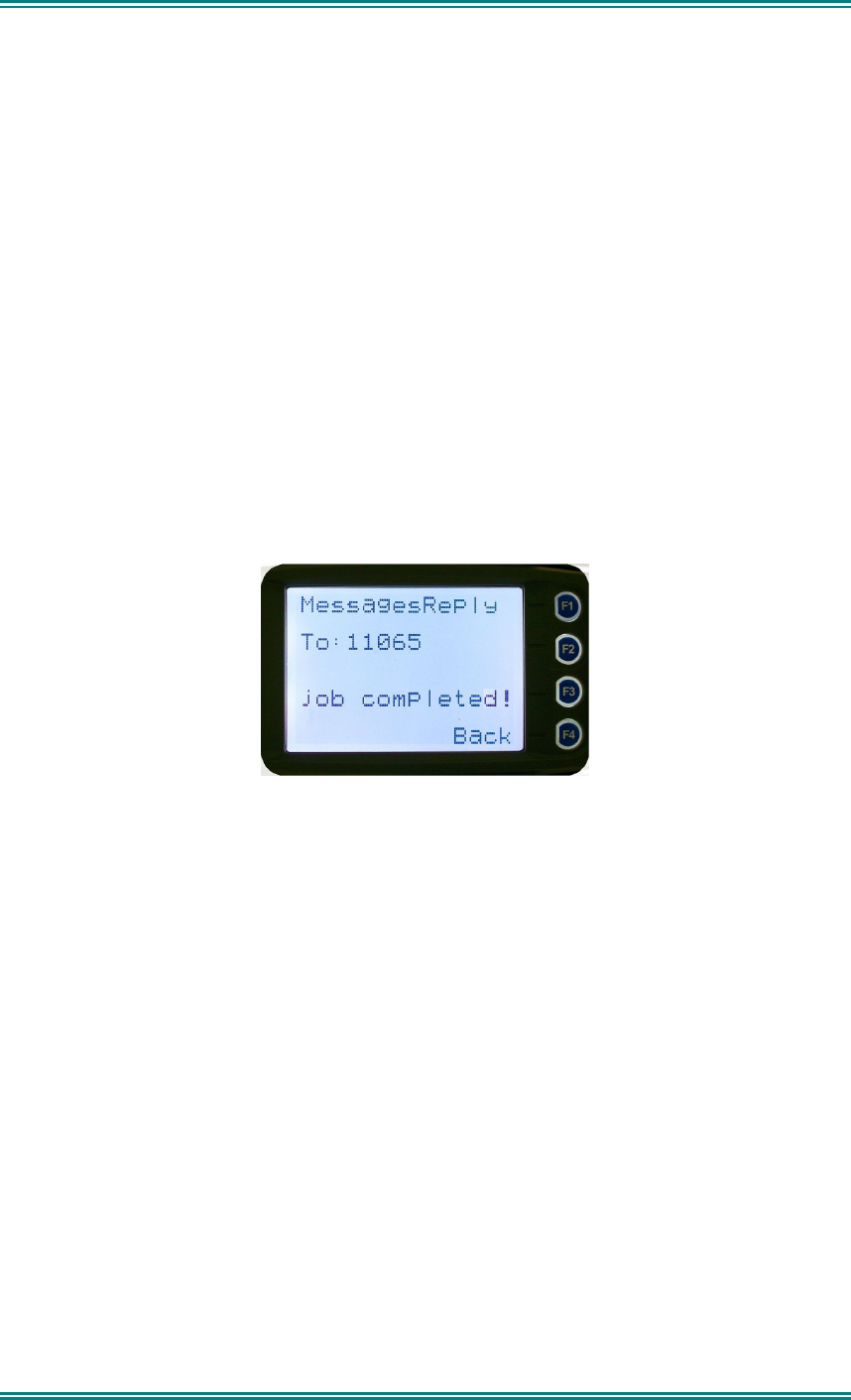
4.2.15.6 Short Message Reply
This menu is used to reply with a pre-defined short message.
This screen shows:
• The destination unit identifier,
• The selected short message.
The short message can be selected from the short message list by using the
▼
and
▲
keys.
A “Reset” function key press (if configured) takes the radio back to the default screen display.
A “
Back
” or “
Menu
” keypress returns to the Message Reply Pop-up screen.
When “
OK
” key is pressed, the selected short message is sent in reply to the received
message, and the radio returns to the default screen.
SRM9030-P25 RADIO – OPERATING INSTRUCTIONS
© ComGroup Australia 2010 page 41 TNM-U-E-0094 Issue 1.2
4.2.15.7 Text Message Reply Screen
This menu is used to reply with a free form text message.
The maximum length of text message is 210 characters.
The characters are entered via the keypad by pressing the relevant key one or more
times to choose each character.
The
▼
key is used to move the curser to the left.
The
▲
key is used to move the curser to the right.
A “Reset/clear” button press and hold for less than one second deletes the character to the
left of the cursor, and moves the curser position to the left by one.
Holding the “Reset/Clear” button down for more than one second deletes all characters from
the curser position to the right. A new character entered is put on the current cursor location.
The ‘
#
’ key is used to toggle upper and lower case.
The “
0
” key is the space key.
When “
Back”
key or “
Menu
” key is pressed, the radio returns to the Message Reply pop-up
screen.
Pressing “
OK
” sends the edited text message in reply to the sender of the message. The
radio returns to the default screen.
4.2.15.8 Send Message (Short or Text)
This menu is used to send either a short message or a text message to another
party.
Select Messages from the main menu and then choose either “SMsg” (Short
Message) or “TXTMsg” (Text Message).
SRM9030-P25 RADIO – OPERATING INSTRUCTIONS
© ComGroup Australia 2010 page 42 TNM-U-E-0094 Issue 1.2
4.2.15.8.1 Short Message Screen
This screen allows the user to view and select a short message. It displays the
selected short message text.
The short message can be selected by using the
▼
and
▲
keys.
A “Reset” function key press (if configured) takes the radio back to the default screen display.
A “
Back
” or “
Menu
” keypress returns to the Message Pop-up screen.
When the “
OK
” key is pressed, the Destination Pop-up screen is shown.
4.2.15.9 Text Message Screen
This screen allows editing and sending a free form text message. A text message can have
a maximum length of 210 characters. The number of characters entered is displayed in the
top right hand side.
The characters are entered via the keypad by pressing the relevant key one or more
times to choose each character.
The
▼
key is used to move the curser to the left.
The
▲
key is used to move the curser to the right.
A “
Reset
” button press and hold for less than one second deletes the character to the left of
the cursor, and moves the cursor position to the left by one.
Holding the “
Reset
” button down for more than one second deletes all characters from the
cursor position to the right. A new character entered is put on the current cursor location.
The
‘#’
key is used to toggle upper and lower case.
SRM9030-P25 RADIO – OPERATING INSTRUCTIONS
© ComGroup Australia 2010 page 43 TNM-U-E-0094 Issue 1.2
When the “
Back
” or “
Menu
” key is pressed, the radio returns to the Message Reply pop-up
screen.
When “
OK
” key is pressed, the Destination Selection Pop-up Menu screen appears.
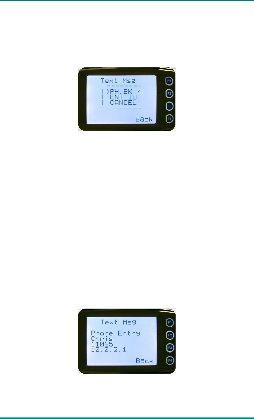
4.2.15.10 Destination Select Pop-Up Menu
This menu allows selection of the message destination.
The selections are:
•
PH. BK:
Selects the destination from the phone book
•
ENT.ID:
Enters the destination unit ID
•
CANCEL:
Cancels the destination selection.
Use the ▼ and ▲ keys to make the selection.
The “
Menu
” or “
Back
” key returns to previous screen, i.e., Short Message Screen, or Edit
Text Message Screen.
A “
Reset
” function key press (if configured) takes the radio back to the default screen
display.
If “
CANCEL
” is selected, pressing “
OK
” returns to the previous screen, i.e., Short Message
Screen, or Edit Text Message Screen.
If “
PH.BK
” is selected, pressing “
OK
” key displays the “Phone Entry Screen”.
If “
ENT.ID
” is selected, pressing “
OK
” key displays the “Enter Unit Id Screen”.
4.2.15.11 Phone Book Selection Screen
This screen allows selection of the destination ID from the Phone Book.
The
▼
and
▲
keys are used to select the phone book entry.
A “Reset” function key press (if configured) takes the radio back to the default screen display.
SRM9030-P25 RADIO – OPERATING INSTRUCTIONS
© ComGroup Australia 2010 page 44 TNM-U-E-0094 Issue 1.2
The “
Menu
” or “
Back
” key returns to the Destination Selection Pop-up screen.
Pressing “OK” key sends the message to the chosen destination ID and the radio
returns to the default screen.
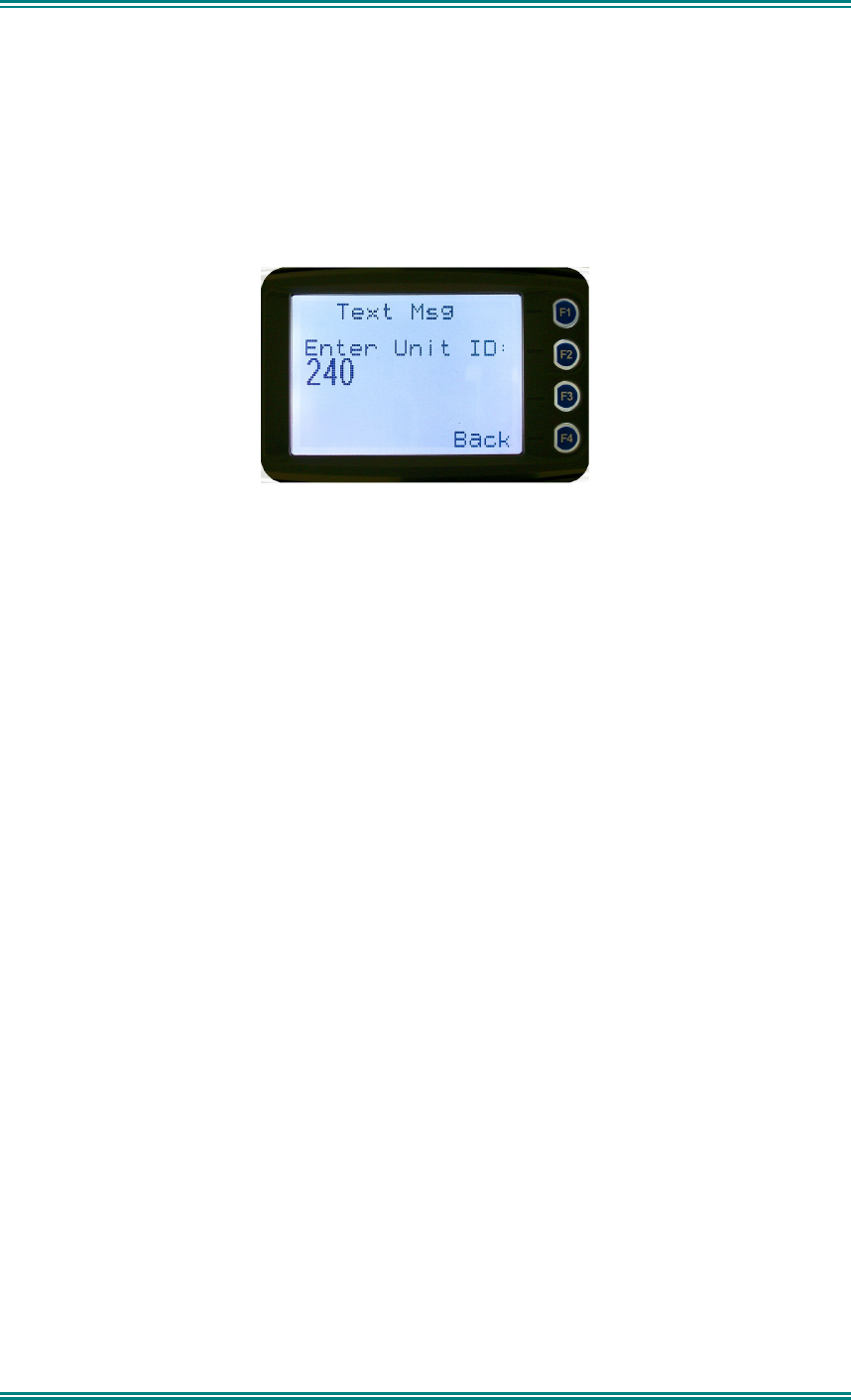
4.2.15.12 Enter Unit ID Screen
This screen allows manual entry of the destination unit ID decimal digits. The valid
range of unit ID: (0 – 16,777,215).
The entered digits can be deleted by using the
▼
key.
The “
Menu
” or “
Back
” key returns to Destination Selection pop-up Menu screen.
A “Reset” function key press (if configured) takes the radio back to the default screen display.
Pressing “
OK
” sends the message to the entered unit ID (providing it is valid). The screen
will return to the default screen.
If the entered unit ID is not valid, or the IP address is not defined, an error beep will sound.
Sending a short message or text message can fail if the destination radio is not available.
SRM9030-P25 RADIO – OPERATING INSTRUCTIONS
© ComGroup Australia 2010 page 45 TNM-U-E-0094 Issue 1.2
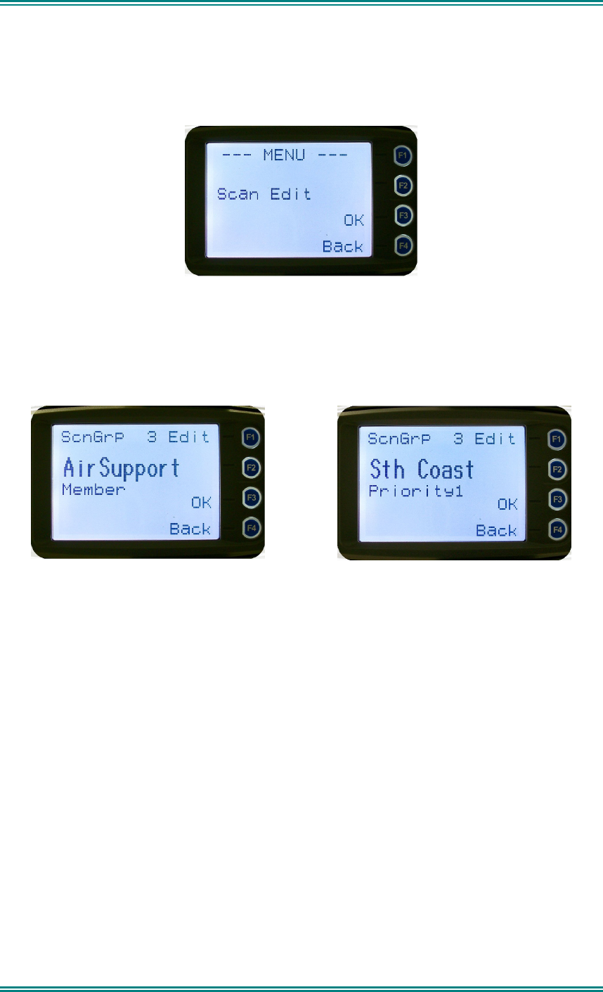
4.2.16 Scan Edit Menu
This menu allows channels in Scan Groups to be added or deleted by the user.
Add and Delete changes to a Scan Group are stored permanently in the radio.
4.2.16.1 Scan Group Edit Screen
When selected, the “
Scan Group Edit
” screen is displayed, which shows the channels within
the Scan Group.
The second line from the top shows the name of the selected channel in the scan group.
The next line shows the channel type, i.e., “Member” if it is a normal member of the scan
group; “Priority” if it is the priority channel; or “Skipped”, if the channel is currently skipped
from the scan group.
The
▼
and
▲
keys select the channel from the scan group list..
When “
Reset
” function key is pressed (if configured), the radio returns to the default screen
display.
When the “
Back
” key or “
Menu
” is pressed, the radio returns to the “
Scan Group Edit
”
screen.
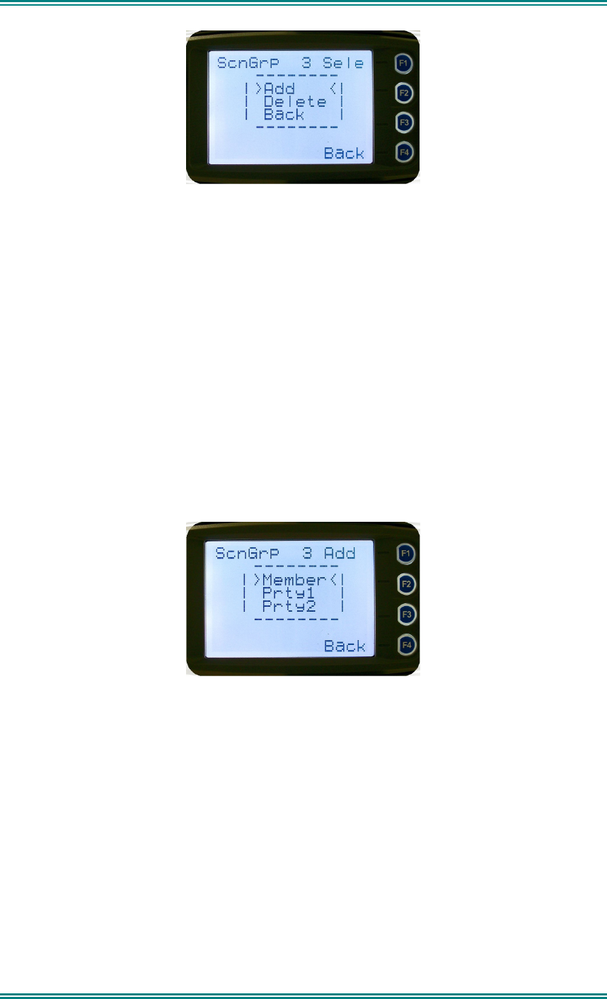
When “
OK
” key is pressed, a pop-up action selection menu is displayed.
SRM9030-P25 RADIO – OPERATING INSTRUCTIONS
© ComGroup Australia 2010 page 46 TNM-U-E-0094 Issue 1.2
The pop-up selections are:
•
Add:
adds a channel to the scan group
•
Delete:
deletes the currently selected channel from the scan group
•
Back:
returns to previous menu screen
The
▼
and
▲
keys make the selection.
The “
Menu
” or “
Back
” key takes the radio back to the “
Scan Edit
” main screen.
A “
Reset
” function key press (if configured) takes the radio back to the default screen
display.
If “
Delete
” is selected, pressing “
OK
” key removes the selected channel from the scan group
and takes the radio back to the default screen display. If scanning is enabled on the current
channel, this action shall result in rescanning. The deletion is permanent.
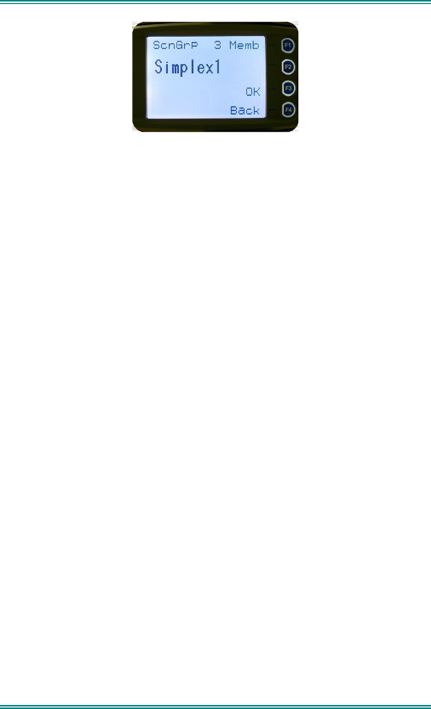
If “
Add
” is selected, pressing “
OK
” key takes the radio to the Scan Group Add Type screen.
The priority level of the channel to add to the scan group is selected from this screen. The
choices are:
•
Member:
A member channel is a normal channel with lowest priority in the scan
group.
•
Prty1:
A Priority 1 channel will have the highest priority in the scan group
•
Prty2:
A Priority 2 channel will have the second highest priority in the scan group.
The priority of the channel is selected using the
▼
and
▲
keys and pressing OK. The Scan
Group Add screen will appear next.
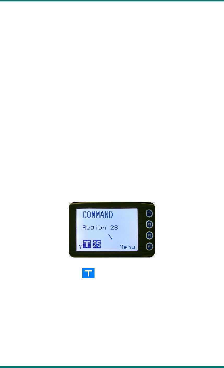
4.2.16.2 Scan Group Add Screen
The “
Scan Group Add
” screen shows channels that are not members of the Scan Group.
SRM9030-P25 RADIO – OPERATING INSTRUCTIONS
© ComGroup Australia 2010 page 47 TNM-U-E-0094 Issue 1.2
The second line from the top shows the name of a channel that is not a member of the Scan
Group.
Other channels that are not members of the scan group can be selected using the
▼
and
▲
keys.
A “
Reset
” function key press (if configured) takes the radio back to the default screen
display.
When the “
Back
” key or “
Menu
” is pressed, the radio returns to the main Scan Edit screen.
When “
OK
” key is pressed,
• If the scan group has less than 15 member channels, the selected non-member
channel is added to the scan group. If scan is enabled on the current channel, the
radio will resume scanning. The radio returns to the default screen. The added
channel is permanent.
Otherwise, an error beep will sound, and the radio will return to the default screen.
4.2.17 No Menu
The No Menu option exists in the FPP for when a menu entry is not required. If all entries
are No Menu, there will be no menu system available. This may be desirable for simple
configurations.
SRM9030-P25 RADIO – OPERATING INSTRUCTIONS
© ComGroup Australia 2010 page 48 TNM-U-E-0094 Issue 1.2
5. COMMON FUNCTIONS AND FACILITIES
5.1 S
WITCH
-O
N
/S
WITCH
-O
FF
The On/Off power switch on the SRM9030 is on the rotary volume control, located on the top
left hand side of the radio control head.
To turn the mobile on, press and hold the volume knob until a beep is heard. The radio will
turn on after about one second.
The display will illuminate and show a ‘Welcome Message’ text as programmed by the Field
Programmer.
After about two seconds, the display will revert to the Channel Screen, at which time the
radio is ready for use.
Pressing and holding the volume knob while the radio is on will turn the radio off, when a low
beep is heard, release the knob.
If the radio Power Down Timer is enabled, the mobile will automatically turn off after several
hours of inactivity (i.e. no keys pressed).
The radio will emit warning beeps for 10 seconds prior to automatically switching off.
Pressing any key will reset this timer.
5.2 D
EFAULT
S
CREEN
–T
RUNKED
M
ODE
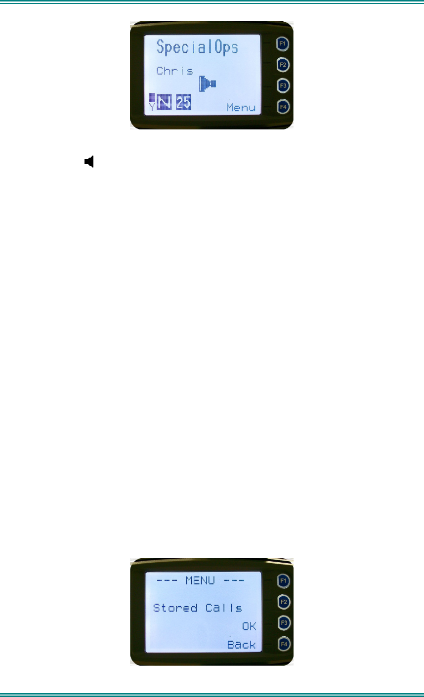
After power up, the radio will show the currently selected Zone and Channel. If the selected
channel is a trunking channel, the radio will scan until it finds the trunked system. This will
typically take a few seconds if the trunked network is available.
Trunked mode is indicated by the icon. The rotating arrow indicates that the radio is
scanning for a trunked network. When the arrow is not shown, the radio is registered with
the trunked network and ready to make or receive a call.
5.3 V
OLUME
A
DJUSTMENT
The Volume Control adjusts the speech level at the radio speaker. The rotary Volume
Control on the SRM9030 is located on the top of the unit.
Note: The radio may be programmed so that the volume cannot be turned off completely.
5.4 R
ECEIVING
(S
INGLE
C
HANNEL
S
CREEN
)
SRM9030-P25 RADIO – OPERATING INSTRUCTIONS
© ComGroup Australia 2010 page 49 TNM-U-E-0094 Issue 1.2
The Speaker Icon
will show when a valid signal is being received and audio will be heard
at the Loudspeaker.
The icon will be shown as an outline when a signal is being received that is not addressing
this radio and hence, is not audible. For instance, another user group may be having a
conversation on another talkgroup when receiving in Selective Mute.
The analogue channel’s receive mute setting can be altered from the Mute Adjust menu.
While on an Analogue channel, both P25 and Analogue FM transmissions will be received.
While on a P25 channel, only P25 transmissions will be received.
To change channels, press the
▼
and
▲
keys while in the channel screen.
Zones can be changed from the
Zone
menu, see Section 4.2.2
5.5 R
ECEIVED
I
NDIVIDUAL
C
ALLS
Unanswered received Individual calls addressed to the radio are stored in radio memory.
The caller Unit ID may be viewed, answered and deleted by the user as desired.
A newly received individual call addressed to the radio sounds an alert tone periodically until
the user presses any key.
If the caller unit ID of a newly received unanswered call is already in the Stored Calls list, the
old Stored Call record of that unit ID will be replaced by the new record and added to the top
of the list.
To view/answer/delete received call records, the
Stored Calls
screen is selected
SRM9030-P25 RADIO – OPERATING INSTRUCTIONS
© ComGroup Australia 2010 page 50 TNM-U-E-0094 Issue 1.2
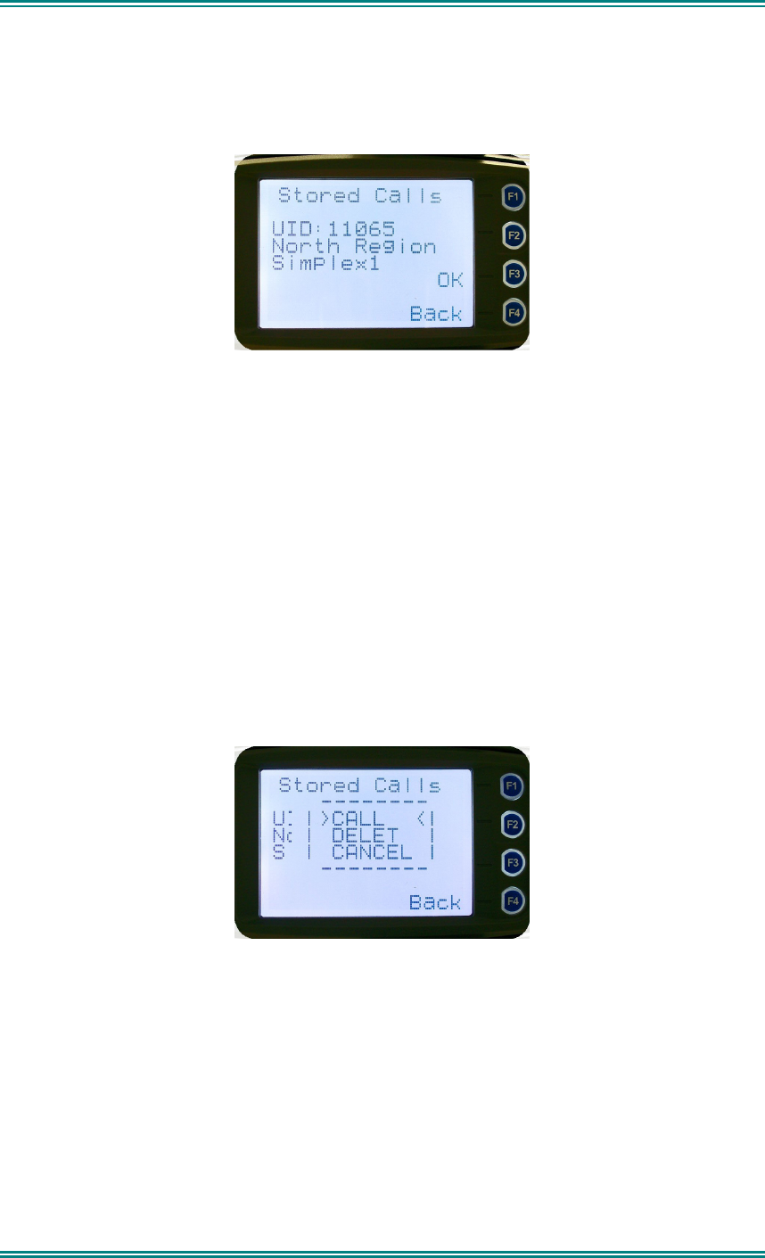
5.5.1 Stored Calls Screen
This screen displays the received individual call records one by one, starting with the
most recently received call record.
On the first line under the menu label, either the name of the caller from the phone
book or the user ID is shown. The user ID is displayed if the ID is not known to the
phone book. The next line has the zone that the call was received on and the line
below shows the channel. If stored calls are empty, NO RECORD is displayed
.
The
▼
and
▲
keys can be used to step through the stored calls. An error beep will sound if
there are no more call records.
A “
Reset
” function key press (if configured) takes the radio back to the default screen
display.
The “
Menu
” or “
Back
” key returns to Menu screen. When “
OK
” key is pressed, a pop up
menu is displayed so that the message can be deleted or party called back.
.
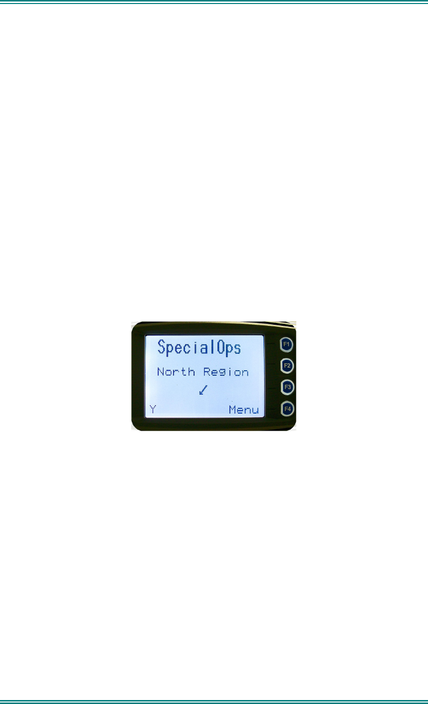
5.5.2 Received Call Pop-Up Menu
The selections are:
•
DELETE:
deletes the call record.
•
CALL:
calls back the caller (set individual call to the caller)
•
CANCEL:
cancels the action selection.
The selection is made with the
▼
and
▲
keys.
The “
Menu
” or “
Back
” key returns to Stored Calls screen.
A “
Reset
” function key press (if configured) takes the radio back to the default screen
display.

SRM9030-P25 RADIO – OPERATING INSTRUCTIONS
© ComGroup Australia 2010 page 51 TNM-U-E-0094 Issue 1.2
If “
DELETE
” is selected, pressing “
OK
” removes the selected call record (being viewed) from
the list. The radio returns to the Stored Calls Screen with the next record being displayed.
If “
CANCEL
” is selected, the
Stored Calls
screen is displayed.
If “
CALL
” is selected, pressing “
OK
” sets the radio to individual calling mode with the ID of
the stored call. A subsequent PTT within the configured time interval will send an individual
call to the ID of the stored call.
5.6 T
RANSMITTING
To avoid interfering with other users of the channel, listen first, or check that the “speaker”
icon is not present, to ensure no transmissions are occurring.
If the speaker icon is shown, there are transmissions present on the channel and the user
should not transmit. The radio may be programmed to prevent transmission on a busy
channel if required.
Hold the microphone a few centimetres from the mouth, press the “Press to talk” (PTT)
switch and note that the TX-LED is RED. Wait for the grant tone, and then speak clearly
across the face of the microphone in a normal conversational manner.
In most systems it is important to wait a short time between pressing PTT and commencing
to speak. This ensures that the path is properly established and avoids lost or distorted
speech.
Use the correct operating procedure and keep transmissions short.
Release the PTT switch as soon as the message is finished.
The talkgroup for a transmission is usually associated with a channel selection. A talkgroup
will address all others that have the same TGID selected.
While on a P25 Channel, the transmission will be P25 digital. For an Analogue channel, the
transmission will be Analogue FM
Note: A Transmit Limit Timer may be setup that limits a continuous transmission on a
channel. The last 10 seconds before the timer expires may be accompanied by warning
beeps.
5.7 S
CAN
/
VOTE
F
UNCTIONS
The Scan/Vote Function allows the sequential searching of up to 16 channels if the selected
zone channel is programmed as a Scan channel, and 15 channels if the selected zone
channel is programmed as a Vote channel, for a valid signal (Carrier + CTCSS / DCS tone
for Analogue FM or Network Access Code for P25). When found, the radio will stop on that
channel until the signal disappears again.
To activate Scanning, select a channel that has been programmed as a Scan channel. Once
selected, the scanning will either start automatically, if programmed, or you will need to press
the programmed scan function button. (Field Programmer configurable).
If a selected zone channel is programmed as a Vote channel, the voting will start
automatically without any other user intervention.
While listening on the channel, the user is able to PTT on that channel. After the signal
disappears, the radio will remain listening on the channel for a short time (Field programmer
configurable, typically 3 seconds) before resuming scanning or voting
SRM9030-P25 RADIO – OPERATING INSTRUCTIONS
© ComGroup Australia 2010 page 52 TNM-U-E-0094 Issue 1.2
If a Priority Channel is assigned to Scan mode, the radio will interleave a check of this
channel between each normal Scan channel.
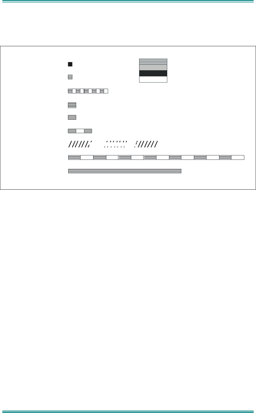
5.7.1 Scan/Vote Screen
Scan can be started by
(1) Pressing the function key that has been assigned the scan function
by the Field Programmer or
(2) Selecting a zone channel that has been assigned to automatically
scan by the Field Programmer, or
(3) Under User Options menu, selecting the SCAN ON option.
Selecting a channel that is associated to a VOTING group, with Scan/Vote
enabled in the FPP, starts voting.
The top line of the display still shows the name of the current selected channel. The second
line of the display shows the name of the current selected zone while scanning/voting.
The Channel can be changed by using the
▼
and
▲
keys. Other channels may be either
Scan or Normal channels, depending on the radio’s configuration.
Scanning/Voting is indicated by a rotating arrow symbol.
When stopped on a channel, the second line from the top shows the name of the channel
from the scan group that the radio stopped on. If stopped on a channel, that channel can be
“skipped” by pressing the skip programmed function key. Once a channel is “skipped” it will
not be scanned for the duration that Zone/Channel selection.
When transmitting on a channel, the second line of display shows the name of the current
channel that the radio is transmitting on.

SRM9030-P25 RADIO – OPERATING INSTRUCTIONS
© ComGroup Australia 2010 page 53 TNM-U-E-0094 Issue 1.2
5.8 K
EYPAD
L
OCK
The Keypad Lock function prevents accidental key presses.
The Control Head has a keypad lock function that may be enabled by the Field Programmer
during configuration. If this function is activated, a key icon will be displayed in the bottom
right-hand side of the display when locked.
The PTT, Alarm Key (if assigned), Reset Key (if assigned) are not locked.
To unlock the keypad, it is necessary to press and hold down the “
OK
” key for 2 seconds.
After 2 seconds, the key icon will disappear and the keys will be enabled.
The keypad will automatically re-lock after a period of 10 seconds following no key activity.
5.9 E
NCRYPTION
In P25 Digital mode, radio channels may be programmed for Encryption.
The encryption state of the selected channel is determined by the radio configuration. An
encrypted channel will display the encryption icon.
A radio channel that has been programmed for encryption will receive either clear or
encrypted traffic. A transmission on this channel will be encrypted.
The encryption icon will not be shown if a received signal is not encrypted when on an
encrypted channel.
The current channel’s transmit encryption key can be temporarily changed from the Crypto
menu.
When in Analogue FM mode, there is a simple voice inversion scrambler for low security
applications.
A double beep will sound at the start of each PTT.
The scrambler function key is assigned using the Field Programmer.
5.10 E
MERGENCY
A
LARM
5.10.1 Receiving Emergency Calls
When an emergency call is being received, a message will be displayed on the default
screen “RxEm” indicating the radio unit sending the emergency call.
5.10.2 Making an Emergency Call
When the emergency key is pressed and held for a time determined by the Field
Programmer, the radio will change to emergency mode. Under emergency mode, the radio
can operate in three FPP configurable modes:
•
Normal:
The radio will continue to respond to PTT, channel change etc. while
displaying the E icon.
•
Frozen:
The default screen will freeze, with the E icon displayed indicating
emergency mode.
•
Blank:
The screen will blank giving no indication to others that the radio is in
emergency mode.

SRM9030-P25 RADIO – OPERATING INSTRUCTIONS
© ComGroup Australia 2010 page 54 TNM-U-E-0094 Issue 1.2
When emergency mode is triggered, the radio can be configured by the FPP to transmit and
receive on a cyclic basis with FPP programmed time periods. The display will show
“TxEm”:Channel No.
During TX, the radio will generate an emergency broadcast call on either the currently
selected channel or an FPP nominated channel.
Others may listen to the automatic transmissions to hear conversations near the radio.
Turning the radio off and on will disable emergency mode.

SRM9030-P25 RADIO – OPERATING INSTRUCTIONS
© ComGroup Australia 2010 page 55 TNM-U-E-0094 Issue 1.2
6. SPECIAL FUNCTION KEYS
Several function keys are simply short cuts to a menu screen. For further information on the
operation of these function keys, refer to the menu descriptions in section 4.
6.1 A
LARM
Sets alarm mode on the radio. All transmissions in alarm mode will have the emergency flag
set.
6.2 A
NNOUNCE
After pressing this button, the next PTT call only will be made to the pre-programmed
Announce group.
6.3 C
HANNEL
U
P AND
D
OWN
These functions change channel in the upward (F3) or downward (F2) directions.
6.4 C
RYPTO
A short cut to the Crypto menu. Allows selection of the encryption key.
6.5 L
OW
P
OWER
Forces the radio to low power. Pressing the function button again puts the radio back to the
power level defined for the current channel. The “forced low power state” is not affected by
channel/zone changes.
The RF power level is indicated by the letter L of H replacing the antenna icon when
transmitting. The bar graph above this icon shows 1 bar for low power and 6 bars for high
power.
6.6 M
ENU
Menu function key used for accessing the menu system. This is normally assigned to the
Menu key (F1).
6.7 M
ODE
A short cut to the Mode menu. Allows the user to change radio modes, for example
from PMR/LMR to P25, or MPT1327 trunking to P25.
6.8 M
UTE
Provides direct access to the “Mute Adjust” menu screen and allows the user to change the
mute level from that screen. The selected mute level will affect all analogue channels.
6.9 R
EPEATER
D
EFEAT
(P25 C
ONVENTIONAL
)
Bypasses the repeater for local chat.
6.10 R
ESET
The reset function is usually assigned to F6, and is used as a cancel function when in a
menu or as a backspace when entering keypad dial-strings.
6.11 S
CAN
The scan function activities the Scanning mode, refer to Section 5.5 for details.
6.12 S
CAN
E
DIT
Enters the Scan Edit sub menu. From here it is possible to Add, Delete or Edit scan
channels.

SRM9030-P25 RADIO – OPERATING INSTRUCTIONS
© ComGroup Australia 2010 page 56 TNM-U-E-0094 Issue 1.2
6.13 S
CRAMBLER
(A
NALOGUE
)
If an analogue channel is selected, then the scrambler function button can activate a simple
voice inversion scrambler for low security applications. Scramble mode is indicated by the
‘SC” indicator icon.
6.14 S
END
DTMF 1 / 2 (
ANALOGUE
)
Sends a pre-defined DTMF dialling string.
6.15 S
KIP
Removes a scan channel from the scan list if the Skip button is pressed while stopped on
that channel. The channel is only restored to the list when the channel is re-selected.
6.16 S
QUELCH
(P25 C
ONVENTIONAL
)
Allows selection of both Digital and Analogue Squelch settings. The squelch is like a filter in
P25 mode where it can be changed to listen to all traffic (monitor), or only your system traffic
(normal), or only your talkgroup or calls to your identity.
6.17 T
ALKAROUND
On a repeater channel only, this function button allows the radio to transmit on the base
station’s output channel, so the user can talk directly to other mobiles on the channel, while
the repeater is out of service or out of range.
When the key is pressed again (or the Channel is changed) the mobile’s transmitter channel
reverts to its normal setting.
Talkaround mode is indicating to the user by a double beep at the start of each PTT.
6.18 Z
ONE
This function provides a shortcut to the detailed zone menu.
6.19 U
NDEFINED
No function assigned to this key.
SRM9030-P25 RADIO – OPERATING INSTRUCTIONS
© ComGroup Australia 2010 page 57 TNM-U-E-0094 Issue 1.2
7. APPENDICES
7.1 A
LERT
T
ONES
A
ND
M
ESSAGES
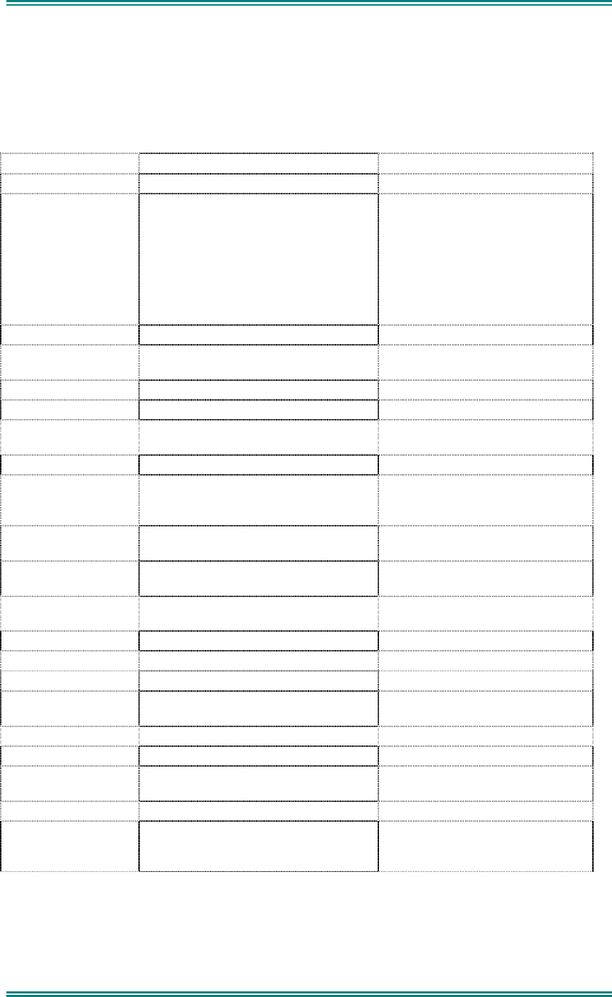
Key Beep
Error Tone
Grant Tone
Beep Alert
Bip Alert
Ring Alert
Urgent Alert
Continuous Alert
2 x Bip Alert
0.05
9000_52b
0.10
0.05
0.05
0.10
0.10
Continuous
Telephone Ring Tone
0.19
Duration Indicated in seconds
880 Hz
Off
1480 Hz
440 Hz
Figure 3 – Alert Tones
SRM9030-P25 RADIO – OPERATING INSTRUCTIONS
© ComGroup Australia 2010 page 58 TNM-U-E-0094 Issue 1.2
7.2 G
LOSSARY
A summary of common radio terms and some other terms used in this document, and their
meanings, are given below.
Term Description Notes
Bank See Zone
Channel A logical combination of
Network Access Code (NAC)
RF Frequency
Default TalkGroup Indentity (TGID)
Encryption Key Index (KID)
Other channel associated parameters
(CTCSS, scan etc)
DTMF Dual Tone Multi Frequency
FPP Field Personality Programmer or Field
Programmer
Used for configuring the radio
options and parameters
FM Frequency Modulation
LED Light Emitting Diode
Monitor Mode of Radio Receive Any P25 signal regardless of NAC
or TGID will be heard
MPT Trunked MPT1327 Trunked Mode
NAC Network Access Code Used as a filter where multiple
networks may share a common
RF frequency
Normal Mute Mode of Radio Receive Only signals with matching NAC
will be heard.
P25 PMR mode using analogue FM used
in as a “fallback” mode with P25
Interoperability requirement
P25 Channel Definition consisting of TX and RX RF
frequencies, NAC and TGID
P25 Conventional Non-Trunked digital, like digital PMR
PMR Private Mobile Radio Mode
PTT Push to Talk
Radio Unit ID Unique identifier allocated to each
radio (0-16,000,000)
RSSI Received Signal Strength Indication
RX Receive
Selective Mode of radio receive Only signals with matching NAC
and TGID or Unit ID will be heard
TX Transmit
Zone A collection of channels (usually
organised by functional group of
users)

SRM9030-P25 RADIO – OPERATING INSTRUCTIONS
© ComGroup Australia 2010 page 59 TNM-U-E-0094 Issue 1.2
7.3 A
CRONYMS
AES Advanced Encryption Standard
APCO Association of Public Communications Officials
ARP Address Resolution Protocol
AVL Automatic Vehicle Location
BER Bit Error Rate
BSS Base Station System
C4FM Four level FM modulation used on the physical air interface
CAI Common Air Interface
CRC Cyclic Redundancy Check
CTCSS Continuous Tone Controlled Selective Squelch
DCS Digital Controlled Squelch
DES-OFB DES Encryption Standard
DSP Digital Signalling Processor
DTMF Dual Tone Multi Frequency
FEP Field Encryption Programmer
FM Frequency Modulation
FNE Fixed Network Equipment
FPP Field Personality Programmer
IP Internet Protocol
LCD Liquid Crystal Display
LET Link Establishment Time
MAB-1 Mobile Option Board (basic)
MAB-2 Mobile Option Board (enhanced I/O)
MPT1327 Trunked Radio Standard
MDP Mobile Data Peripheral
MRC Mobile Routing and Control
NAC Network Access Code, see also NID
NID Network ID
P25 APCO Project 25
PPP Point to Point Protocol
PLA Programmable Logic Array
PMR Private Mobile Radio
PTT Push To Talk
RCP Radio Control Protocol
RF Radio Frequency
SLIP Serial Line Internet Protocol
SS Supplementary Service
TCP/IP Transmission Control Protocol / Internet Protocol
TGID Talk Group ID
TIA Telecommunications Industry Association
UDP User Datagram Protocol

SRM9030-P25 RADIO – OPERATING INSTRUCTIONS
© ComGroup Australia 2010 page 60 TNM-U-E-0094 Issue 1.2
7.4 C
OMPLIANCE WITH
RF E
NERGY
E
XPOSURE
G
UIDELINES
(U
NITED
STATES
AND
C
ANADA
)
RF ENERGY EXPOSURE AWARENESS AND CONTROL INFORMATION AND OPERATIONAL
INSTRUCTIONS FOR FCC OCCUPATIONAL USE REQUIREMENTS.
Before using your ComGroup Australia mobile two-way radio, read this important RF energy
awareness and control information and operational instructions to ensure compliance with the FCC’s
RF exposure guidelines.
NOTICE: This radio is intended for use in Occupational/ controlled conditions in a mobile
application where users have full knowledge of their exposure and can exercise control over
their exposure to meet FCC limits. This radio device is NOT authorised for general population,
consumer, or any other use.
This two-way radio uses electromagnetic energy in the radio frequency (RF) spectrum to provide
communications between two or more users over a distance. It uses radio frequency (RF) energy or
radio waves to send and receive calls. RF energy is one form of electromagnetic energy. Other forms
include, but are not limited to, electric power, sunlight and x-rays. RF energy, however, should not be
confused with these other forms of electromagnetic energy, which when used improperly can cause
biological damage. Very high levels of x-rays, for example, can damage tissues and genetic material.
Experts in science, engineering, medicine, health and industry work with organizations to develop
standards for exposure to RF energy. These standards provide recommended levels of RF exposure
for both workers and the general public. These recommended RF exposure levels include substantial
margins of protection. All two-way radios marketed is North America are designed, manufactured and
tested to ensure they meet government established RF exposure levels. In addition, manufacturers
also recommend specific operating instructions to users of two-way radios. These instructions are
important because they inform users about RF energy exposure and provide simple procedures on
how to control it. Please refer to the following websites for more information on what RF energy
exposure is and how to control your exposure to assure compliance with established RF exposure
limits.
http:l/www.fcc. gov/oet/rfsafety/rf-fags. htm 1
http://www.osha.gov/SLTC/radiofrequencvradiation/index.htmi
Federal Communications Commission Regulations:
The FCC rules require manufacturers to comply with the FCC RF energy exposure limits for mobile
two-way radios before they can be marketed in the U.S. When two-way radios are used as a
consequence of employment, the FCC requires users to be fully aware of and able to control their
exposure to meet occupational requirements. An exposure awareness label is attached to the
equipment directing users to specific awareness information.
Compliance with RF Exposure Standards
Your TMC two-way radio is designed to comply with a number of national and international standards
and guidelines (listed below) regarding human exposure to radio frequency electromagnetic energy.
This radio complies with the IEEE (FCC) and ICNIRP exposure limits for Occupational/ Controlled RF
exposure environment at duty factors of up to 50% talk 50% listen and is authorised by the FCC for
occupational use. In terms of measuring RF energy for compliance with the FCC exposure guidelines,
your radio radiates measurable RF energy only while it is transmitting (during talking), not when it is
receiving (listening) or in standby mode.
Your ComGroup Australia two-way radio complies with the following RF energy exposure standards
and guidelines:

SRM9030-P25 RADIO – OPERATING INSTRUCTIONS
© ComGroup Australia 2010 page 61 TNM-U-E-0094 Issue 1.2
• United States Federal Communications Commission, Code of Federal Regulations; 47CFR
part 2 sub-part J
• American National Standards Institute (ANSI) / Institute of Electrical and Electronic Engineers
(IEEE) C95. 1-1992
• Institute of Electrical and Electronic Engineers (IEEE) C95.1-1999 Edition
• Industry Canada RSS-102
RF Exposure Compliance and Control Guidelines and
Operating Instructions
To control exposure to yourself and others and ensure compliance with the Occupational/ Controlled
environment exposure limits always adhere to the following procedures.
Guidelines:
• User awareness instructions should accompany the device when transferred to other users.
• Do not use this device if the operational requirements described herein are not met.
Instructions:
• Transmit no more than the rated duty factor of 50% of the time. To transmit (talk), push the
Push-To-Talk button. To receive calls, release the PTT button. Transmitting 50% of the time,
or less, is important because this radio generates measurable RF energy exposure only when
transmitting (in terms of measuring for standards compliance).
• Transmit only when people outside the vehicle are at least the recommended minimum lateral
distance away, as shown in Tables 1, 2 and 3, from a properly installed according to
installation instructions, externally-mounted antenna.
NOTES:
Table 1a) lists the recommended minimum lateral distance for bystanders in an uncontrolled
environment from the transmitting antenna for the SRM9000AC (150MHz-174MHz) mobile rated
power (25 watts) installed in a vehicle. Table 1b) lists the recommended minimum lateral distance for
occupational/ controlled use.
Table 2a) lists the recommended minimum lateral distance for bystanders in an uncontrolled
environment from the transmitting antenna for the SRM9000TU and SRM9000UW (406.1MHz-
512MHz) mobile rated power (25 watts) installed in a vehicle. Table 2b) lists the recommended
minimum lateral distance for occupational/ controlled use.
Table 3a) lists the recommended minimum lateral distance for bystanders in an uncontrolled
environment from the transmitting antenna for the SRM9000X8 (806MHz-870MHz) mobile rated power
(25 watts) installed in a vehicle. Table 3b) lists the recommended minimum lateral distance for
occupational/ controlled use.
SRM9030-P25 RADIO – OPERATING INSTRUCTIONS
© ComGroup Australia 2010 page 62 TNM-U-E-0094 Issue 1.2
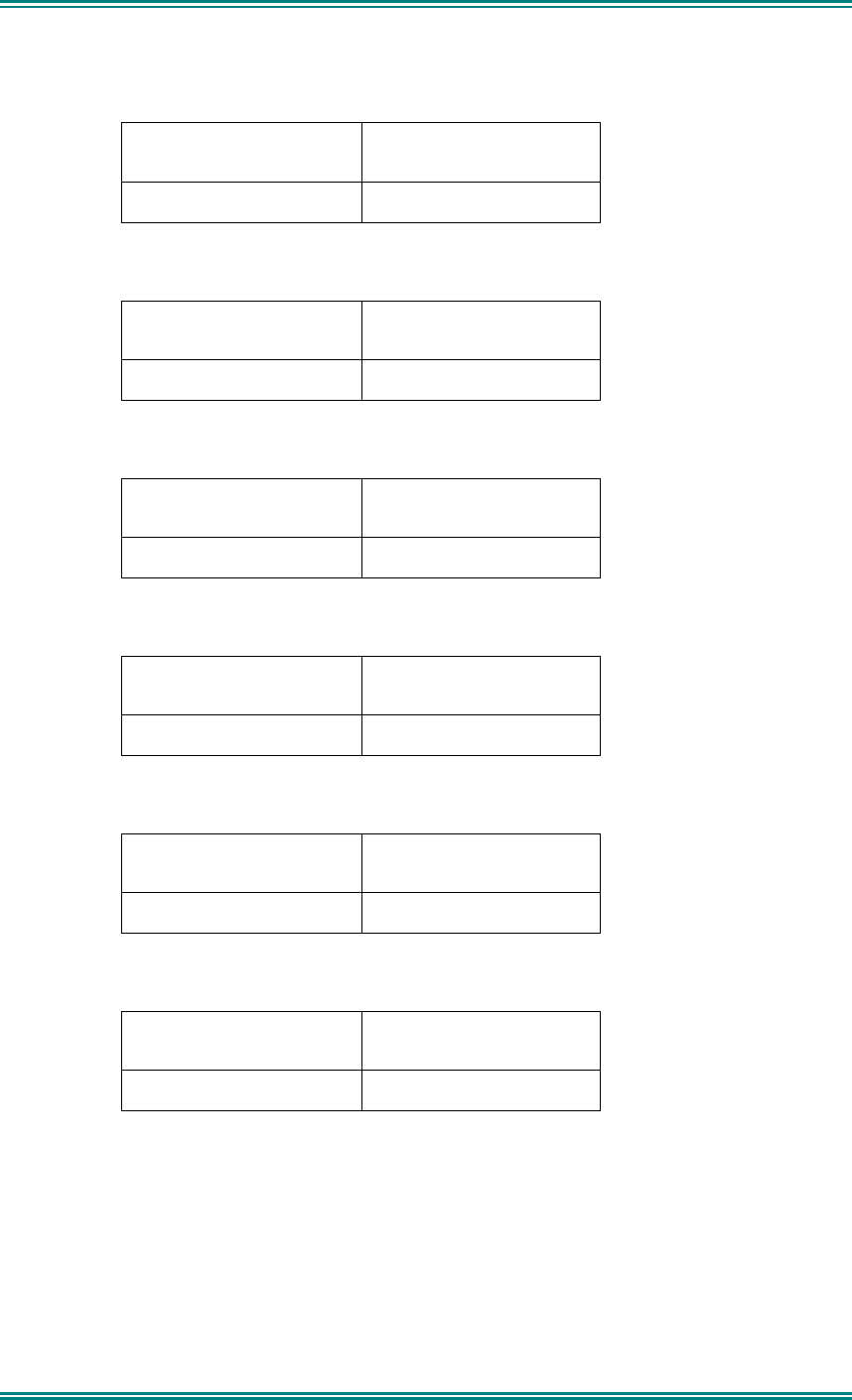
Table 1a). Rated Power and Recommended Lateral Distance for
General Population uncontrolled exposure for SRM9000AC
(150MHz to 174MHz).
Rated Power of Vehicle-
installed Mobile Two-way
Radio
Recommended Minimum
Lateral Distance from
Transmitting Antenna
25 watts with λ/4 dipole
(2.14dBi gain)
90cm (35.5 inches)
Table 1b). Rated Power and Recommended Lateral Distance for
Occupational/ Controlled exposure for SRM9000AC
(150MHz to 174MHz).
Rated Power of Vehicle-
installed Mobile Two-way
Radio
Recommended Minimum
Lateral Distance from
Transmitting Antenna
25 watts with λ/4 dipole
(2.14dBi gain)
40cm (15.75 inches)
Table 2a). Rated Power and Recommended Lateral Distance for
General Population uncontrolled exposure for SRM9000TU and SRM9000UW
(406.1MHz to 512MHz).
Rated Power of Vehicle-
installed Mobile Two-way
Radio
Recommended Minimum
Lateral Distance from
Transmitting Antenna
25 watts with λ/4 dipole
(2.14dBi gain)
75cm (29.5 inches)
Table 2b). Rated Power and Recommended Lateral Distance for
Occupational/ Controlled exposure for SRM9000TU and SRM9000UW
(406.1MHz to 512MHz).
Rated Power of Vehicle-
installed Mobile Two-way
Radio
Recommended Minimum
Lateral Distance from
Transmitting Antenna
25 watts with λ/4 dipole
(2.14dBi gain)
34cm (13.5 inches)
Table 3a). Rated Power and Recommended Lateral Distance for
General Population uncontrolled exposure for SRM9000X8
(806MHz to 870MHz).
Rated Power of Vehicle-
installed Mobile Two-way
Radio
Recommended Minimum
Lateral Distance from
Transmitting Antenna
25 watts with λ/4 dipole
(2.14dBi gain)
55cm (21.7 inches)
Table 3b). Rated Power and Recommended Lateral Distance for
Occupational/ Controlled exposure for SRM9000X8
(806MHz to 870MHz).
Rated Power of Vehicle-
installed Mobile Two-way
Radio
Recommended Minimum
Lateral Distance from
Transmitting Antenna
25 watts with λ/4 dipole
(2.14dBi gain)
24.6cm (9.7 inches)

SRM9030-P25 RADIO – OPERATING INSTRUCTIONS
© ComGroup Australia 2010 page 63 TNM-U-E-0094 Issue 1.2
Vehicle Installation Instructions:
The antenna(s) used for the SRM9000 series of mobile two-way radios must be installed to provide a
separation distance of at least 90cm (35.5 inches) from all persons for SRM9000AC (150-174MHz),
75cm (29.5 inches) for SRM9000TU and SRM9000UW (406.1-512MHz) and 55cm (21.7 inches) for
SRM9000X8 (806-870MHz). The gain of the antenna(s) may not be greater than 0dBd (2.14dBi).
If the required separation distance extends beyond the physical boundary of the vehicle, the antenna
must be installed on the center of the roof ONLY and must be installed in a vehicle having the
following characteristics in order to prevent bystanders from being exposed to levels exceeding the
limits set for General Population/ Uncontrolled exposure environment:
• All passengers must be sitting under a solid metal roof
• The rooftop width must be at least 130cm (51 inches)
Mobile Antenna:
• Install the antenna at the center of the roof or the center of the trunk deck, taking into account
the bystander exposure conditions of backseat passengers and recommended minimum
lateral distances in Tables 1a), 2a) and 3a). These mobile antenna installation guidelines are
limited to metal body motor vehicles or vehicles with appropriate ground planes.
• The antenna installation must additionally be in accordance with:
a) The requirements of the antenna manufacturer/supplier
b) Instructions in the Radio Installation Manual, including minimum antenna cable lengths.
c) The installation information of how to install the antenna to facilitate recommended
operating distances to all potentially exposed persons.
• Use only ComGroup Australia approved supplied antenna or ComGroup Australia approved
replacement antenna. Unauthorized antennas, modifications, or attachments could damage
the radio and may violate FCC regulations.
Approved Accessories
• This radio meets the FCC RF exposure guidelines when used with the ComGroup Australia
accessories supplied or designated for the product. Use of other accessories may not ensure
compliance with the FCC’s RF exposure guidelines and may violate FCC regulations.
• To obtain a list of ComGroup Australia approved accessories see contact details below or
visit the following website which lists approved accessories: http://www.comgroup.net.au
Contact Information
For additional information on exposure or other information, please contact
ComGroup Australia Pty. Ltd.
1270 Ferntree Gully Road
Scoresby
Victoria, 3179
Australia
Telephone +61 3 9730 3800
Facsimile +61 3 9730 3968
Email orderdesk@comgroup.net.au
Website www.comgroup.net.au