Simplex Time Recorder 31032021330 Wireless Alarm Transceiver User Manual 330 fire transmitter
Simplex Time Recorder Company Wireless Alarm Transceiver 330 fire transmitter
Users Manual

P/N 330.MAN Rev. 1.0
2006 Comm
ercial Wireless Systems International, LLC
1
Fire Transmitter Model 330
Description:
The model 330 fire transmitter is a UL864 listed device specifically designed for connection
to a normally open dry contact output. The input is selectable for two types of supervised
wiring configurations referred to as Style 1 or
Style
2 in this manual. The transmitter is fully
supervised for tamper, low battery, RF signal integrity and wiring faults. The transmitter is
powered by a single 3 volt lithium battery as listed under the specifications section of this
manual and the label on the product. The model 330 is intended to be used with
Commercial Wireless Systems International, LLC Model CP
-
3000 Fire Alarm Control Panel.
Refer to the CP-3000 FACP installation instructions, part number 3000.MAN Rev. 1 for
addi
tional details.
Programming:
The 330 must be enrolled into the CP-3000 control panel before installing the device.
The
Model 330 will not report Alarms, Supervisory or trouble signals unless it is enrolled
into the CP-3000 control panel. Enrollment must be performed while in front of the CP-
3000 FACP. Place the CP-3000 FACP in enrollment mode then install the battery in the
model 330 transmitter observing polarity marked on the battery holder. The model 330
serial number will be displayed on the CP-3000 FA
CP
along with programming options.
Refer to the CP-3000 control panel installation instructions for further details on enrollment
and
transmitter programming options. After the model 330 is enrolled, remove the battery
and reinstall it only at the transmit
ters mounting location.
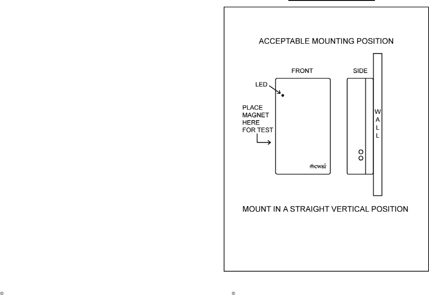
Installation:
Select an accessible location that is not prone to tampering or accidental damage
The
mounting surface should be relatively flat and capable of accepting screws or anchors. The
330 is to be installed in an indoor dry location. Exposure to weather or corrosive conditions
may damage the unit. It must be mounted on a vertical surface so that the CWSI label can
be read correctly. Perform the signal test described in this manual prior to and after
permanently mounting the u
nit
. An 18 gage copper wire pair should be used to connect
the 330 to the dry contacts to be monitored. Wire runs should be as short as possible,
contained within one room and not routed near fluorescent lighting or equipment generating
electrical noise such as generators, air conditioners, etc. The wires should enter the 330
through the hole provided near the screw terminal block. Under no circumstances are the
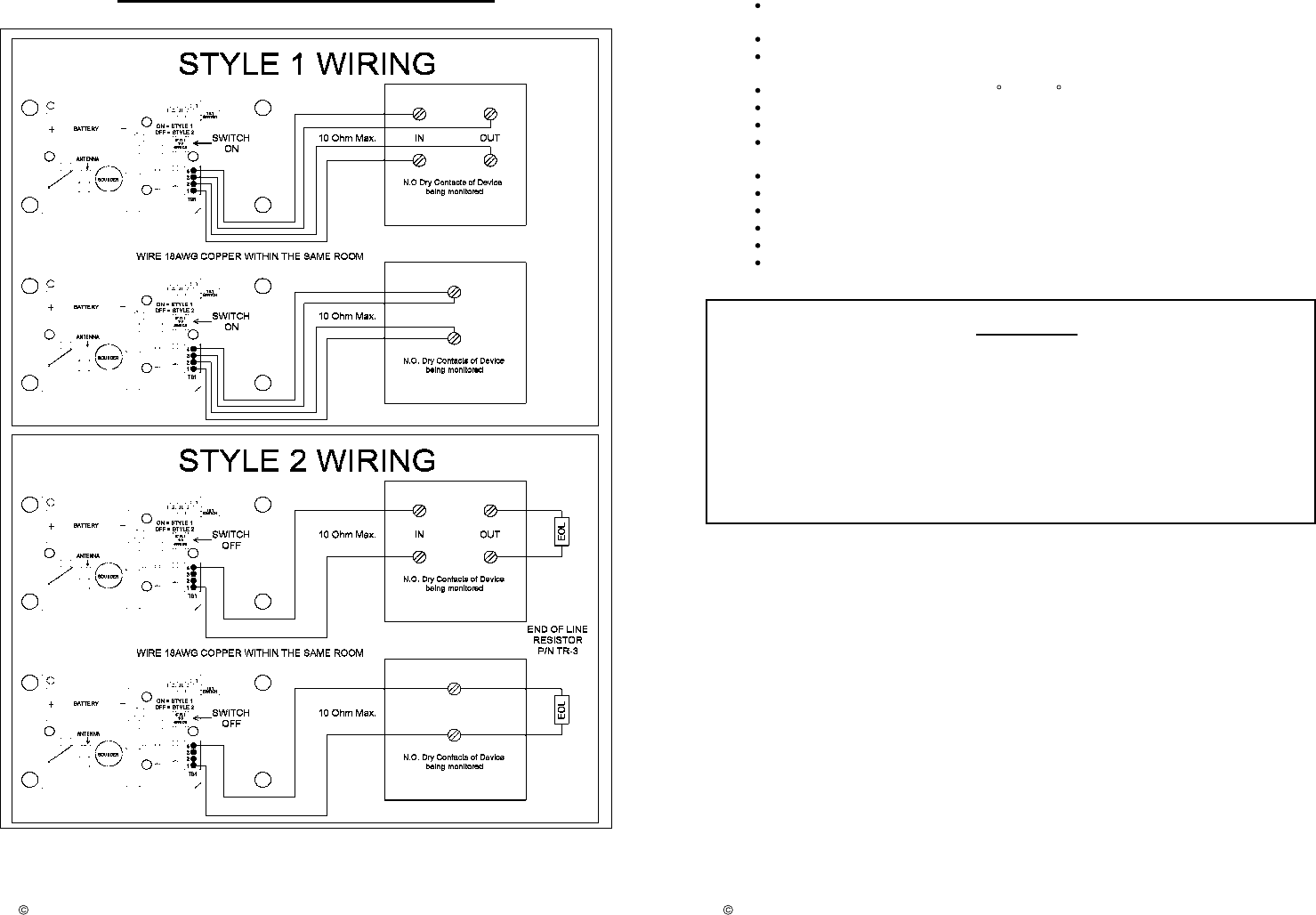
wires to be run near or draped over the printed 330 printed circuit board. Style 1 or Style 2
wi
ring can be selected with SW2 on the board. Refer to figure 2 for proper
wiring
connection
. When Style 2 wiring is selected,
the Model TR
-
3 EOL resistor provided must be
connected either as recommended by the manufacturer of the device being monitored or
directly across the dry contact terminals of the of the monitored device. Multiple sets of
contacts on the monitored equipment may be wired in parallel and connected to a single
330.
Caution:
only one
monitored
device may be connected to a single Model 330.
After connecting the wires to the terminal block, install the battery,
mount
the enclosure
back
on
the wall using the keyholes then push the front portion of the enclosure onto the
back until the case snaps closed. Be careful not to bend the transmitter’s antenna. Perform
the
S
ignal
T
est
and
Alarm Test
as outlined in this manual.
P/N 330.MAN Rev. 1.0
2006 Comm
ercial Wireless Systems International, LLC
2
Cautions:
1. Make sure the battery is firmly installed in the battery clip.
2. The unit must be secured tightly to the wall, so as to not be dislodged.
3. Test the unit after any service or battery change or as often as local or national codes
dictate.
Following the codes:
The Model 330 must be installed and maintained in accordance with the National Fire
Protection Association’s Standards (NFPA), the National Electrical Code
and all local
fire and electrical requirements. When connecting to
other
equipment, follow the
instructions and recommendations of that manufacturer.
Alarm
Operation:
When the wires of the model
330 are shorted:
1
. An initial alarm signal is transmitted
.
2. A 30 second delay occurs. If during this delay the alarm condition is reset and the
alarm
cycle
is ended
.
3.
A continued alarm condition causes a repeat alarm transmission.
4. Another 30 second delay as in step 2 occurs.
5.
A
continued alarm
condition
causes a repeat alarm transmission.
6. Step 5 repeats at 60 second intervals until reset.
LED:
The LED will flash when any signal is sent from the transmitter.
Alarm Test
:
Before testing, notify the proper authorities that maintenance is being performed and the
system will be temporarily out of service. Activate the dry contact output being monitored by
the Model 330 transmitter or manually short the wires to simulate dry contact closure. Verify
an alarm is received at the control panel.
Signal Test:
The
test must be performed while the transmitter is held in its intended mounting location.
Initiate the test by placing a strong magnet along the upper right side of the
transmitter
case
(figure 1). The model 330 piezo sounder will beep twice if the transmitter is located
within acceptable reception range of a repeater or
CP
-3000 FACP
.
If two beeps are not
heard within 5 seconds of initiating the signal test then relocate the model 310 mounting
position closer to the nearest repeater or control panel and perf
orm the test again. Continue
this procedure until 2 beeps are achieved.
Do not mount the transmitter unless 2 beeps are
heard when performing the signal test. This test
must
be performed before and after
transmitter installation. Note: A CWSI model AR-
3
re
peater or Control Panel must be
installed and turned on before running this test.
Low battery:
The battery voltage is periodically tested under load. In the event that a low battery is
detected, a low battery signal wil
l be sent
immediately
and
repeated every 90
seconds for a
minimum of seven days. Where more than one type of trouble exists, all will be repeated
every
90
seconds.
Battery Installation and Replacement:
Warning:
Always install a new battery of one of the approved types as listed in the
Specifications section of this manual and the product label
.
When a battery is first
inserted, a low battery test is performed. If the battery passes the test, The unit should not
send a low battery signal.
If the battery does not pass this test, th
e unit
will continue to send
a low battery until a good battery is installed.
P/N 330.MAN Rev. 1.0
2006 Comm
ercial Wireless Systems International, LLC
3
To replace the battery:
1. Place the CP-3000 Control Panel in Test mode to prevent any unwanted alarms. (Refer
to the CP
-
3000 manual)
2. Open the transmitter’s case by holding and pulling the front of the case away from the
mounting surface. The back will remain on the wall. A tamper signal will be transmitted. The
battery will now be exposed. Remove the battery and dispose of properly.
3. To insure proper power down sequence, wait a minimum of 20 seconds before installing
a new battery.
4. Install a new approved 3 volt lithium battery in the battery compartment following the
polarity diagram inside the compartment. A tamper trouble signal should be indicated on
the CP
-
3000
Control Panel upon installation of the new battery.
5. Close the transmitter case by pushing the front onto the back. Make sure excess wire
does not lie onto the transmitter board. There should be no gaps where the front and back
case sections meet.
6.
Test the Model 330 as described in
Alarm Testing
section.
7. If the Model 330 does not function for alarm testing as described in item 6 then start over
at step 2. If it still doesn’t operate correctly then replace the entire unit.
8. Remove the panel
from test mode. (Refer to the CP
-
3000 manual)
Tamper:
The Model 330 has an on board tilt sensor that will cause a tamper signal to be transmitted
if the 330 case is opened or removed from its mounting position. Upon detection of a
tamper, a
trouble
signal is sent
immediately
and repeated every 90 seconds until the
condition is restored. Where more than one type of trouble exists, all will be repeated
within
90
seconds.
EOL
/Wiring Fault
Trouble:
If the wiring from the
Model
330 to the monitored device opens preventing the EOL from
being detected in Style 2
wiring
configuration or if any of the wires in the Style 1
configuration is disconnected, a trouble signal will be sent and repeated every 90 seconds.
Where more than one type of trouble exists, all will
be repeated
within
90
seconds.
P/N 330.MAN Rev. 1.0
2006 Comm
ercial Wireless Systems International, LLC
4
330 MOUNTING
Figure 1
P/N 330.MAN Rev. 1.0
2006 Comm
ercial Wireless Systems International, LLC
5
330 WIRING DIAGRAM
Figure 2
P/N 330.MAN Rev. 1.0
2006 Comm
ercial Wireless Systems International, LLC
6
Specifications:
Battery Type: 3 Volt Lithium; Duracell DL123A, Sanyo CR123A, Panasonic
CR123A.
Battery Life: 12 Months Minimu
m
Battery Replacement: Upon Low battery report and/or during annual
maintenance.
Operating Temperature Range: 0
C to +49 C.
Operating Humidity Range
0 to 9
5% RH.
Testing: Follow
this manual and
NFPA 72 or local requirements.
Transmission: In compliance with FCC part 15 for reception on equipment
manufactured by Commercial Wireless Systems International, LLC.
Test Transmission: Every 90 seconds.
Compatibility: Commercial Wireless Systems International, LLC Model CP
-
3000.
Size: 4.75 Inches high, 2.55 Inches w
ide, 1.58 Inches deep.
Weight 6.4 oz.
Input Current Rating:
19.1 ua
Normal Supervisory.
25
u
a. Alarm.
Initiating loop rating: 3
Vdc, 1ma.
FCC Statement
Important: Any changes or modifications not expressly approved by the party responsible
for compl
iance could void the user’s authority to operate the equipment
This device complies with part 15 of the FCC Rules. Operation is subject to the following
two conditions: (1) This device may not cause harmful interference, and (2) this device
must accept any interference received, including interference that may cause undesired
operation
.

P/N 330.MAN Rev. 1.0
2006 Comm
ercial Wireless Systems International, LLC
7
COMMERCIAL WIRELESS SYSTEMS INTERNATIONAL, LLC
ONE YEAR LIMITED WARRANTY
Commercial Wireless Systems International, LLC (“Seller”), 10794 N.W.
53 Street, Sunrise, Florida 33351, warrants this product to be free from
defects in workmanship for
two
years from date of purchase, under
normal use and service. Seller’s obligation is limited to repairing or
replacing, at it’s option, free of charge for parts and l
abor any part proven
to be defective in materials or workmanship. Seller shall have no
obligation under this warranty otherwise if: (1) the product is altered,
repaired or serviced by anyone other than the seller, (2) the product is
damaged from accidents, acts of God, misuse, tampering or abuse, (3)
product is not installed and operated in accordance with the instructions
provided by the seller. In case of defect, contact the fire alarm
professional who installed and maintains your fire alarm system or the
seller for product repair.
This
two
year Limited Warranty is in lieu of all other express warranties,
obligations, or liabilities. There are no express warranties that extend
beyond the face hereof. In no case shall seller be liable to anyone for
any consequential or incidental for breach of this or any other warranty,
express or implied, or upon any other basis of liability whatsoever, even
if the loss or damage is caused by the seller’s own negligence or fault.
Seller shall have no liability for any personal injury, property damage, or
other loss based on a claim that the product failed to operate correctly.
However, if the seller is held liable, whether directly or indirectly, for any
loss or damage arising under this warranty or otherwise, regardless o
f
cause of origin, Seller’s maximum liability shall not in any case exceed
the purchase price of the product, and shall be the complete and
exclusive remedy against the Seller.
P/N 330.MAN Rev. 1.0
2006 Comm
ercial Wireless Systems International, LLC
8
NOTES

P/N 320.MAN Rev. 1.0
2006 Commercial Wireless Systems International, LLC
1
Heat Detector with Transmitter
Models 320/321
Description:
The models 320 and 321 are UL listed combination fixed temperature/rate of-rise sensors
with temperature ratings of 135
F/57
C (
Model
320) or 194
F/90
(
Model
321) and a b
uilt in
transmitter. These heat detectors are intended for use in property protection applications or
for non-
life
-safety installations where smoke detection is not practical or appropriate.
The
transmitter is fully supervised for tamper
,
low battery and RF signal integrity. The
transmitter is powered by a single 3 volt lithium battery as listed under the specifications
section of this manual and the label on the product. The models 320 and 321 are intended
to be used with Commercial Wireless Systems International, LLC Model CP-3000 Fire
Alarm Control Panel. Refer to the CP-3000 FACP installation instructions, part number
3000.MAN Rev. 1 for additional details. Warning: For life-safety installations, smoke
detectors must be used, in lieu of, or in addition t
o mechanical heat detectors.
Programming:
The 320/321 must be enrolled into the CP-3000 FACP before installing the device.
The
Models 320/321 will not report Alarms or trouble signals unless it is enrolled into the
CP
-3000 control panel. Enrollment must
be
performed while in front of the CP-
3000
FACP. Place the CP-3000 FACP in enrollment mode then install the battery in the
model
320
-321 transmitter observing polarity marked on the battery holder. The model 320/321
serial number will be displayed on the CP-3000 FACP along with programming options.
Refer to the CP-3000 control panel installation instructions for further details on enrollment
and transmitter programming options. After the model 310 is enrolled, remove the battery
and reinstall it only at the
transmitters mounting location.
Installation:
Select an accessible location that is not prone to tampering or accidental damage.
The
Model 320
-321 must be installed and maintained in accordance with the National Fire
Protection Association’s Standards (NFPA), the National Electrical Code
and
all local
fire and electrical requirements. The mounting surface should be relatively flat and
capable of accepting screws or anchors. The 320-321 is to be installed in an indoor dry
location. Exposure to weather or corrosive conditions may damage the unit. Perform the
signal test described in this manual prior to and after permanently mounting the unit
.
It is acceptable to mount the heat detector on a ceiling tile only if the tile is secured with
fasteners and can not be removed or the Heat Detector is installed across a ceiling tile
metal support where each mounting screw is attached to separate ceiling tiles (figure 1).
Mark the mounting location using the keyholes in the back box. Install screws and or
anchors. Mount the back box on the screws. Install the battery in the battery holder. Place
the front of the unit on the back box and install the closing screws. Be careful not to bend
the transmitter
’s
antenna. Perform the S
ignal
T
est
and Alarm Test as outlined in this
manual.
P/N 320.MAN Rev. 1.0
2006 Commercial Wireless Systems International, LLC
2
Cautions:
1. Make sure the battery is firmly installed in the battery clip.
2. The unit must be secured tightly to the mounting surface, so as to not be dislodged.
3. Test the unit after any service or battery change or as often as local or national codes
dictate.
Alarm
Operation:
If eit
her the fixed temperature
or Rate of Rise Sensor is activated, the following will occur:
1.
An initial alarm signal is transmitted
.
2. A 30 second delay occu
rs. The alarm cycle is ended if the heat sensor is
restored during
the 30 second delay.
3. The continued alarm condition causes a repeat alarm transmission.
4. Another 30 second delay as in step 2 occurs.
5. The continued alarm causes a repeat alarm transmission.
6. Step 5 repeats at 60 second intervals un
til reset.
LED:
The LED will flash when any signal is sent from the transmitter.
Alarm Test:
The rate-
of
-rise mechanism may be subject to reduced sensitivity over time. Annual testing
of the rate-
of
-rise operation is therefore recommended. Before testing, notify the proper
authorities that maintenance is being performed and the system will be temporarily out of
service.
Warning:
Only the Rate of R
ise
elements of 320-321 models are self-
restoring, and may be tested using a hair dryer or heat gun. When testing the ROR
element, to prevent the activation of the fixed temperature element, the heat source
must not exceed the fixed temperature rating of the detector. If the fixed temperature
element is tripped, the heat detector sensor will need replacement.
Acti
vate the ROR
element and verify an alarm is received at the control panel.
Heat Detector Sensor Replacement
If the fixed temperature element is tripped the heat sensor will need replacement. C
ontact
an authorized dealer or Commercial Wireless Systems Inte
rn
ational, LLC for a replacement
s
ensor
. Order
p/n
20FR for the model 320 and p/n 21FR for the model 321
.
To Replace the Sensor:
1. Place the CP-3000 Control Panel in Test mode to prevent any unwanted alarms. (Refer
to the CP
-
3000 manual)
2. Open the Heat Detector case by removing the four screws holding it closed. A tamper
signal will be transmitted. Separate the front from the back to expose the battery. Remove
the battery.
3.
Turn the heat sensor ¼ turn counter-
clockwise
to expose the heat sensor w
ires
.
D
isconnect the wires and resistor.
Do not discard the resistor.
4. Reattach the wires and resistor
to
a new temperature sensor. Attach the sensor to
its
base by turning it ¼ turn clockwise.
5
.
Replace the battery and close the Heat Detector case with the four screws. Test the unit
as described in
Alarm
Testing.
6. If the Heat Detector does not function for alarm testing as described in item 5 then start
over at step 2. If it still doesn’t operate correctly then replace the entire unit.
7
. Remove
the panel from test mode. (Refer to the CP
-
3000 manual)
P/N 320.MAN Rev. 1.0
2006 Commercial Wireless Systems International, LLC
3
Signal Testing:
The test must be performed while the heat detector is held in its intended mounting
location. Initiate the test by placing a strong magnet along the middle left side of the
320/321 case (figure 2). The model 320/321 piezo sounder will beep twice if the transmitter
is located within acceptable range of a repeater or CP-3000 FACP. If two beeps are not
heard within 5 seconds of initiating the signal test then relocate the model 310 mounti
ng
position closer to the nearest repeater or control panel and perform the test again. Continue
this procedure until 2 beeps are achieved. Do not mount the transmitter unless 2 beeps are
heard when performing the signal test. This test
must
be performed before and after
transmitter installation. Note: A CWSI model AR-
3
repeater or
CP
-
3000
Control Panel must
be installed and turned on before running this test.
Low
battery:
The battery voltage is periodically tested under load. In the event that a low battery is
detected, a low battery signal will be sent
immediately
and repeated every
90 seconds
for a
minimum of seven days. Where more than one type of trouble exists, all will be repeated in
increments of
90
seconds.
Battery Installation and Replacement:
Warning:
Always install a new battery of one of the approved types as listed in the
Specifications section of this manual and the product label. When a battery is first
inserted, a low battery test is performed. If the battery passes the test, The unit should not
send a low battery signal.
If the battery does not pass this test, the unit
will continue to send
a low battery until a good battery is installed.
To replace the battery:
1. Place the CP-3000 Control Panel in Test mode to prevent any unwanted alarms. (Refer
to the CP
-
3000 manual)
2. Open the Heat Detector case by removing the four screws holding it closed. A tamper
signal will be transmitted. Separate the front from the back to expose the battery. Remove
the battery and dispose of properly.
3.
To insure proper power down sequence, wait a minimum of 20 seconds before installing
a new battery.
4. Install a new approved 3 volt lithium battery in the battery compartment following the
polarity diagram inside the compartment. A tamper trouble signal should be indicated on
the CP
-
3000 Control Panel upon installation of the new battery.
5. Close the Heat detector case and reinstall the four screws.
6. Test the Heat Detector
as described in
Alarm Testing
section.
7. If the Heat Detector does not func
tion
for alarm testing as described in item 6 then start
over at step 2.
If it still doesn’t operate correctly then replace the entire unit.
8
. Remove the panel from test mode. (Refer to the CP
-
3000 manual)
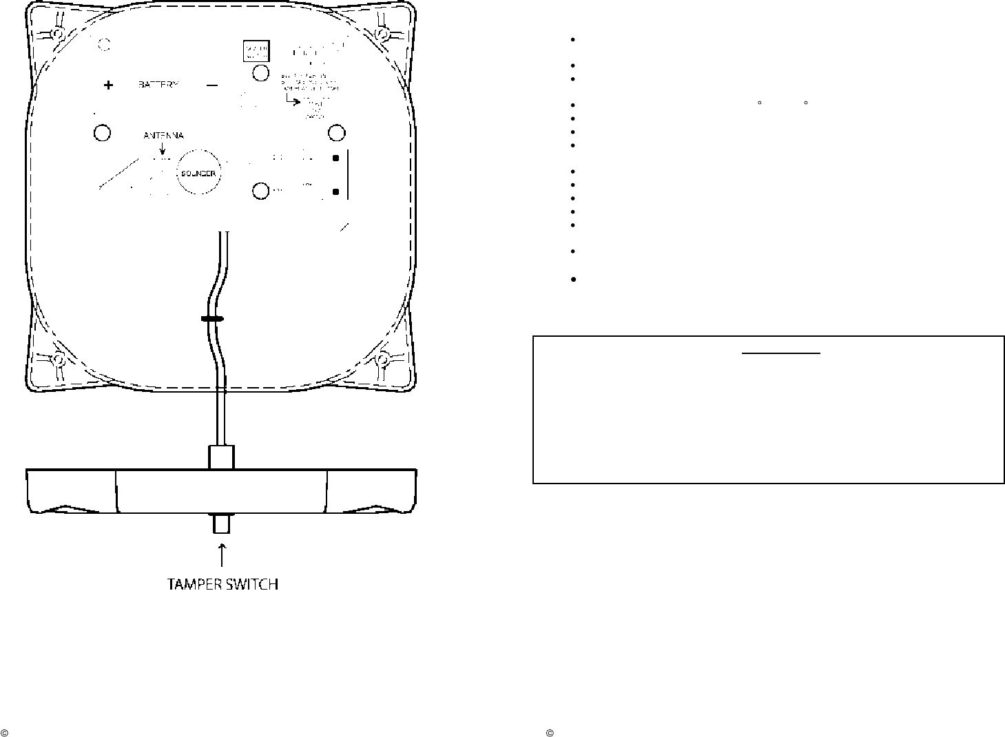
Tamper:
The Model 320-
321
contains
two
tamper switches. One monitors opening of the case and
the other one monitors device for removal from its mounting position. Upon detection of a
tamper
from either switch, a tamper signal is sent and repeated every
90
seconds until the
condition is restored. Where
more than one type of trouble exists, all will be repeate
d within
90 seconds.
P/N 320.MAN Rev. 1.0
2006 Commercial Wireless Systems International, LLC
4
ACCEPTABLE MOUNTING
TO CEILING TILE
Figure 1
Figure 2
P/N 320.MAN Rev. 1.0
2006 Commercial Wireless Systems International, LLC
5
P/N 320.MAN Rev. 1.0
2006 Commercial Wireless Systems International, LLC
6
Specifications:
Battery Type: 3 Volt Lithium; Duracell DL123A, Sanyo CR123A, Panasonic
CR123A.
Battery Life: 12 Months Minimum
Battery Replacement: Upon Low battery report and/or during annual
maintenance.
Operating Temperature Range: 0
C to +38 C.
Operating Humidity Range
5
to
9
5% RH
non
-
condensing
.
Testing: Follow
this manual and
NFPA 72 or local
requirements.
Transmission: In compliance with FCC part 15 for reception on equipment
manufactured by Commercial Wireless Systems International, LLC.
Test Transmission: Every 90 seconds.
Compatibility: Commercial Wireless Systems International, LLC Model
CP
-
3000.
Size: 4.
57
Inches high,
4.57
Inches wide,
3.25
Inches deep.
Weight 6.4 oz.
Maximum Installation Temperature Model 320: 100°F (38°C)
Model 321: 150°F (65.6°C)
Alarm Temperature: Model 320: 135°F (57°C)
Model 321: 194°F (90°C)
Rate
-
of
-
Rise
Threshold: 15°F (8.3°C) per minute
FCC Statement
Important: Any changes or modifications not expressly approved by the party responsible
for compliance could void the user’s authority to operate the equipment
This device complies with part 15 of the FCC Rules. Operation is subject to the following
two conditions: (1) This device may not cause harmful interference, and (2) this device
must accept any interference received, including interference that may cause undesired
operation
.

P/N 320.MAN Rev. 1.0
2006 Commercial Wireless Systems International, LLC
7
COMME
RCIAL WIRELESS SYSTEMS INTERNATIONAL, LLC
ONE YEAR LIMITED WARRANTY
Commercial Wireless Systems International, LLC (“Seller”), 10794 N.W.
53 Street, Sunrise, Florida 33351, warrants this product to be free from
defects in workmanship for
two
years from date of purchase, under
normal use and service. Seller’s obligation is limited to repairing or
replacing, at it’s option, free of charge for parts and labor any part proven
to be defective in materials or workmanship. Seller shall have no
obligation under this warranty otherwise if: (1) the product is altered,
repaired or serviced by anyone other than the seller, (2) the product is
damaged from accidents, acts of God, misuse, tampering or abuse, (3)
product is not installed and operated in accordance with the instructions
provided by the seller. In case of defect, contact the fire alarm
professional who installed and maintains your fire alarm system or the
seller for product repair.
This two year Limited Warranty is in lieu of all other express warranties,
ob
ligations, or liabilities. There are no express warranties that extend
beyond the face hereof. In no case shall seller be liable to anyone for
any consequential or incidental for breach of this or any other warranty,
express or implied, or upon any other basis of liability whatsoever, even
if the loss or damage is caused by the seller’s own negligence or fault.
Seller shall have no liability for any personal injury, property damage, or
other loss based on a claim that the product failed to operate correctly
.
However, if the seller is held liable, whether directly or indirectly, for any
loss or damage arising under this warranty or otherwise, regardless of
cause of origin, Seller’s maximum liability shall not in any case exceed
the purchase price of the product, and shall be the complete and
exclusive remedy against the Seller.

P/N 310.MAN Rev. 1.0
2006 Commercial Wireless Systems International, LLC
1
Fire Pull Station with Transmitter
Model 310
Description:
The model 310 is a self-contained dual action lexan fire pull station with a built in
transmitter. It is a UL38 listed device and meets the ADA requirement of a 5-lbs. Max
imum
pull force to activate. Operating instructions are molded into the handle along with Braille
text.
The Model 310 is fully supervised for tamper, low battery and
RF
signal integrity. The
transmitter is powered by a single 3 volt lithium battery as listed under the specifications
section of this manual and the label on the product. The model 310 is intended to be used
with Commercial Wireless Systems International, LLC Model CP-3000 Fire Alarm Control
Panel. Refer to the CP-3000 FACP installation instructions, part number 3000.MAN Rev. 1
for additional details.
Programming:
The 310 must be enrolled into the CP-3000 FACP before installation of the device.
The
Model 310 will not report Alarms or trouble signals unless it is enrolled into the CP-
3000 control panel. Enrollment must be performed while in front of the CP-3000 control
panel. Place the CP-3000 FACP in enrollment mode then install the battery in the model
310 transmitter observing polarity marked on the battery holder
.
The model 310 serial
number
will be displayed on the CP-3000 FACP along with programming options. Refer to
the CP-3000 control panel installation instructions for further details on enrollment and
transmitter programming options. After the model 310 is enrolled, remove the battery an
d
reinstall it only at the transmitters mounting location.
Installation:
Select an accessible location that is not prone to tampering or accidental damage.
The
Model 310 must be installed and maintained in accordance with the National Fire
Protection Association’s Standards (NFPA), the National Electrical Code and
within
the limits defined by the Americans with Disabilities Act (ADA) or per national/local
requirements
.
For ADA compliance, if the clear floor space only allows forward
approach to an object, the maximum forward reach height allowed is 48-
inches
(121.92cm). If the clear floor space allows parallel approach by a person in a
wheelchair, the maximum side reach height allowed is 54
-
inches (137.16cm).
The mounting surface should be relatively flat and capable of accepting screws or anchors.
The 310 is to be installed in an indoor dry location. Exposure to weather or corrosive
conditions may damage the unit.
The Pull Station must be mounted on a vertical surface so
that the CWSI label can be read cor
rectly.
Perform the signal test described in this
manual prior to and after permanently mounting the unit
.
Fasten the back box to the
mounting surface using the 4 screws and anchors supplied. Install the battery in the battery
holder.
Carefully s
nap the fr
ont
assembly on to the back box making sure all four clips have
been fully inserted (figure 2)
.
Be careful not to bend the transmitter
’s
antenna. Perform the
S
ignal
T
est
and
Alarm Test
as outlined in this manual.
P/N 310.MAN Rev. 1.0
2006 Commercial Wireless Systems International, LLC
2
Cautions:
1. Make sure the battery is
firmly installed in the battery clip.
2. The unit must be secured tightly to the wall, so as to not be dislodged.
3. Test the unit after any service or battery change or as often as local or national codes
dictate.
Alarm
Operation:
To activate
an alarm from
the pull station, push in and pull down
on
the handle. The word
‘ACTIVATED’ appears after the handle is pulled down
.
The pull station remains in the
activated position until reset.
When the pull station handle is pulled:
1. An initial alarm signal is
transmitted
.
2. A 30 second delay occurs. If during this delay the alarm condition is reset and the ala
rm
cycle
is ended
.
3. The continued alarm condition causes a repeat alarm transmission.
4. Another 30 second delay as in step 2 occurs.
5. The continued
alarm causes a repeat alarm transmission.
6. Step 5 repeats at 60 second intervals until reset.
To reset the pull station, insert the key into the lock and rotate ¼ turn counterclockwise.
Open the door until the handle returns to normal then close and lock the door. Closing the
door automatically resets the switch to the normal position. Opening the door with the key
will not activate the alarm switch.
LED:
The LED will flash when any signal is sent from the transmitter.
Alarm
T
est:
Before testing, noti
fy the proper authorities that maintenance is being performed and the
system will be temporarily out of service.
To activate an alarm from the pull station, push in
and pull down
on
the handle. The word ‘ACTIVATED’ appears after the handle is pulled
down
.
Verify an alarm is received at the control panel. T
he pull station remains in the
activated position until reset.
To reset the pull station, insert the key into the lock and rotate ¼ turn counterclockwise.
Open the door until the handle returns to normal then close and lock the door. Closing the
door automatically resets the switch to the normal position. Opening the door with the key
will not activate the alarm switch.
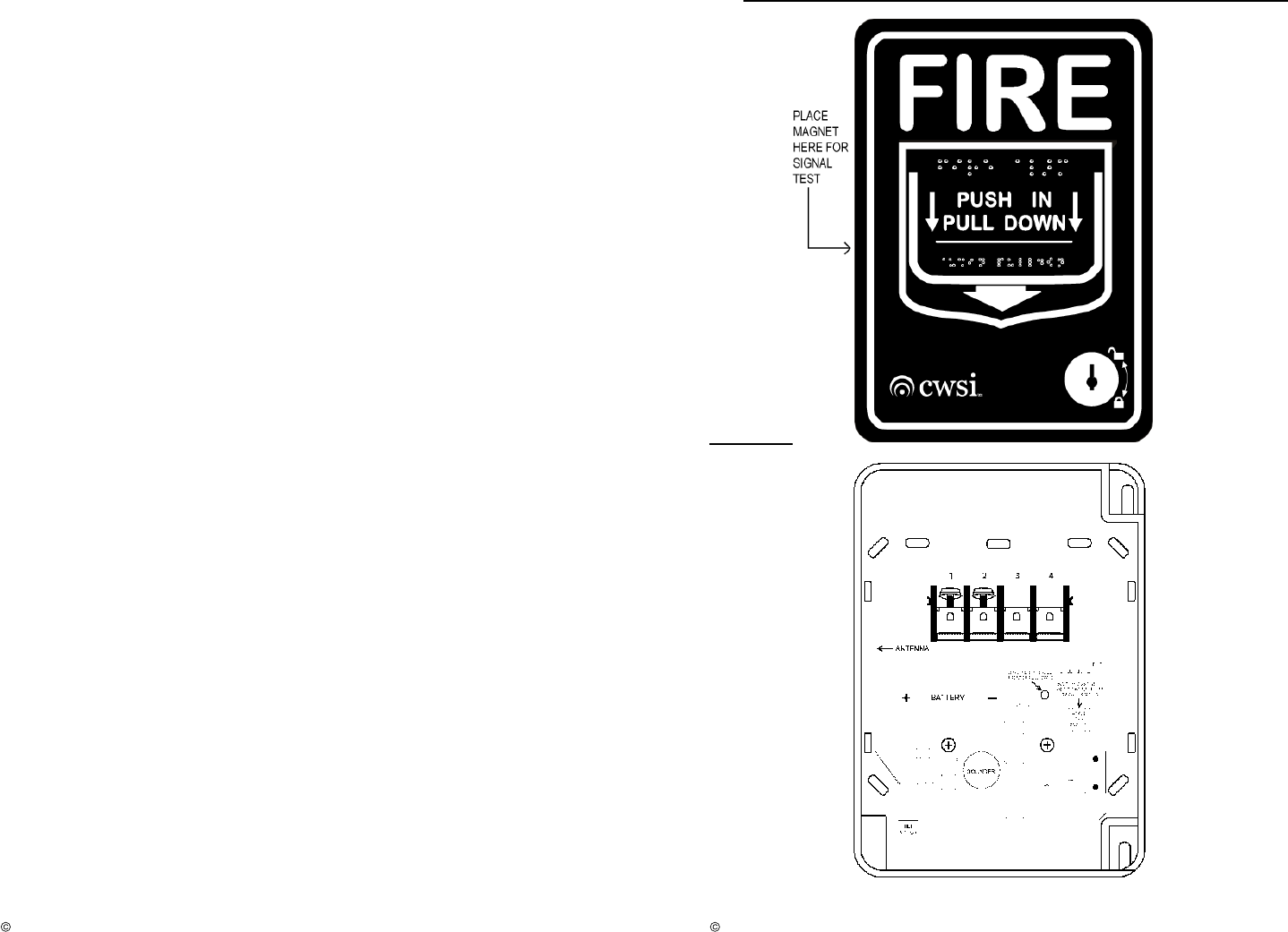
Signal Testing:
The test must be performed while the pull station is held in its intended mounting location.
I
nitiate
the test
by placing a strong magnet along the
middle
left
side of the 310 case
(figure
1)
. The model 310 piezo sounder will beep twice if the transmitter is located within
acceptable range of a repeater or CP-3000 FACP.
If
two beeps are not heard within 5
seconds of initiating the signal test then relocate the model 310 mounting position closer to
the nearest repeater or control panel and perform the test again. Continue this procedure
until 2 beeps are achieved. Do not mount the transmitter unless 2 beeps are heard when
performing the signal test. This test
must
be performed before and after transmitter
installation. Note: A
CWSI
model AR-
3
repeater or
CP
-
3000
Control Panel must be
installed and turned on before running this
test.
P/N 310.MAN Rev. 1.0
2006 Commercial Wireless Systems International, LLC
3
Low battery:
The battery voltage is periodically tested under load In the event that a low battery is
detected, a low battery signal will be
sent immediately and
repeated every
90
seconds
for a
minimum of seven days. Where more than one type of trouble exists, all will be repeated
every 90 seco
nds.
Battery Installation and Replacement:
Warning:
Always install a new battery of one of the approved types as listed in the
Specifications section of this manual and the product label. When a battery is first
inserted, a low battery test is performed. If the battery passes the test, The unit should not
send a low battery signal.
If the battery does not pass this test, the unit
will continue to send
a low battery until a good battery is installe
d.
To replace the battery:
1. Place the CP-3000 Control Panel in Test mode to prevent any unwanted alarms. (Refer
to the CP
-
3000 manual)
2.
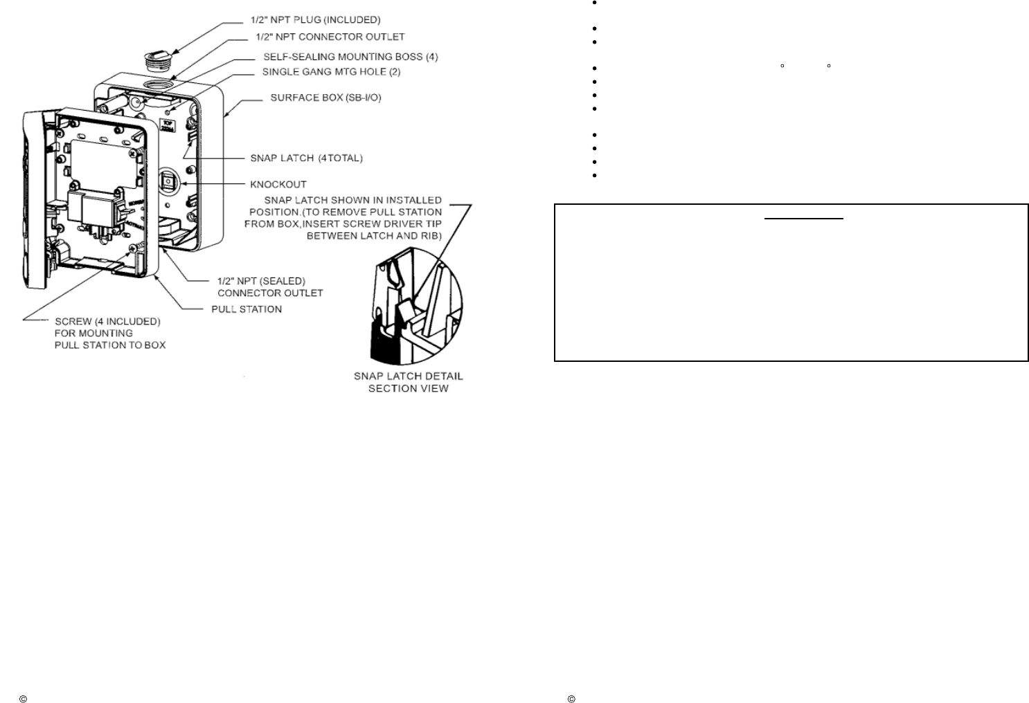
Open the Pull Station door using the key provided. This will not cause an alarm.
Separate the Pull Station front from the back by releasing the snap latches as shown in
figure 2.
Remove the battery and dispose of properly.
3. To insure proper power down sequence, wait a minimum of 20 seconds before installing
a new battery.
4. Install a new approved 3 volt lithium battery in the battery compartment following the
polarity diagram inside the compartment. A tamper trouble signal should be indicated on
the CP
-
3000 Control Panel
upon installation of the new battery
.
5.
Reattach the Pull Station by firmly pushing the front onto the back making sure the snap
latches clip into the back box. Close the Pull Station door and lock it with the key.
6. Test the
Pull Station
for alarm operation
.
7. If the Pull Station does not function for alarm operation as described in item 6 then start
over at step 2.
If it still doesn’t operate correctly then replace the entire unit.
8
. Remove the panel from test mode. (Refer to the CP
-
3000 manual)
Tamper:
The Model 310 has an on board tilt sensor that will cause a tamper signal to be tr
ansmitted
if the 310 case is opened or removed from its mounting position. Upon detection of a
tamper, a tamper signal is sent immediately and repeated every
90
seconds until the
condition is restored. Where more than one type of trouble exists, all will b
e repeated
with
in
90
seconds.
P/N 310.MAN Rev. 1.0
2006 Commercial Wireless Systems International, LLC
4
MOUNT PULL STATION IN A VERTICAL POSITION ONLY
Figure 1
P/N 310.MAN Rev. 1.0
2006 Commercial Wireless Systems International, LLC
5
Figure 2
P/N 310.MAN Rev. 1.0
2006 Commercial Wireless Systems International, LLC
6
Specifications:
Battery Type: 3 Volt Lithium; Duracell DL123A, Sanyo CR123A, Panasonic
CR123A.
Ba
ttery Life: 12 Months Minimum
Battery Replacement: Upon Low battery report and/or during annual
maintenance.
Operating Temperature Range: 0
C to +49 C.
Operating Humidity Range 0 to
95
% RH.
Testing: Follow
this manual and
NFPA 72 or local requirements.
Tra
nsmission: In compliance with FCC part 15 for reception on equipment
manufactured by Commercial Wireless Systems International, LLC.
Test Transmission: Every 90 seconds.
Compatibility: Commercial Wireless Systems International, LLC Model CP
-
3000.
Size: 5.5
0
Inches high,
4.12
Inches wide,
2.80
Inches deep.
Weight 6.4 oz.
FCC Statement
Important: Any changes or modifications not expressly approved by the party responsible
for compliance could void the user’s authority to operate the equipment
This device complies with part 15 of the FCC Rules. Operation is subject to the following
two conditions: (1) This device may not cause harmful interference, and (2) this device
must accept any interference received, including interference that may cause undesired
o
peration.

P/N 310.MAN Rev. 1.0
2006 Commercial Wireless Systems International, LLC
7
COMMERCIAL WIRELESS SYSTEMS INTERNATIONAL, LLC
ONE YEAR LIMITED WARRANTY
Commercial Wireless Systems International, LLC (“Seller”), 10794 N.W.
53 Street, Sunrise, Florida 33351, warrants this product to be free from
defects in workmanship for
two
years from date of purchase, under
normal use and service. Seller’s obligation is limited to repairing or
replacing, at it’s option, free of charge for parts and labor any part proven
to be defective in materials or workmanship. Seller shall have no
obligation under this warranty otherwise if: (1) the product is altered,
repaired or serviced by anyone other than the seller, (2) the product is
damaged from accidents, acts of God, misuse, tampering or abuse, (3)
product is not installed and operated in accordance with the instructions
provided by the seller. In case of defect, contact the fire alarm
professional who installed and maintains your fire alarm system or the
seller for product repair.
This
two
year Limited Warranty is in lieu of all other express warranties,
obligations, or liabilities. There are no express warranties that extend
beyond the face hereof. In no case shall seller be liable to anyone for
any consequential or incidental for breach of this or any other warranty,
expr
ess or implied, or upon any other basis of liability whatsoever, even
if the loss or damage is caused by the seller’s own negligence or fault.
Seller shall have no liability for any personal injury, property damage, or
other loss based on a claim that the product failed to operate correctly.
However, if the seller is held liable, whether directly or indirectly, for any
loss or damage arising under this warranty or otherwise, regardless of
cause of origin, Seller’s maximum liability shall not in any case exceed
the purchase price of the product, and shall be the complete and
exclusive remedy against the Seller.