Simplicity 1694847 Parts Manual Large Frame Snowthrowers
1694914 to the manual fece7532-c54d-42cc-948d-9510bc866914
2014-12-13
: Simplicity Simplicity-1694847-Parts-Manual-127346 simplicity-1694847-parts-manual-127346 simplicity pdf
Open the PDF directly: View PDF ![]() .
.
Page Count: 44
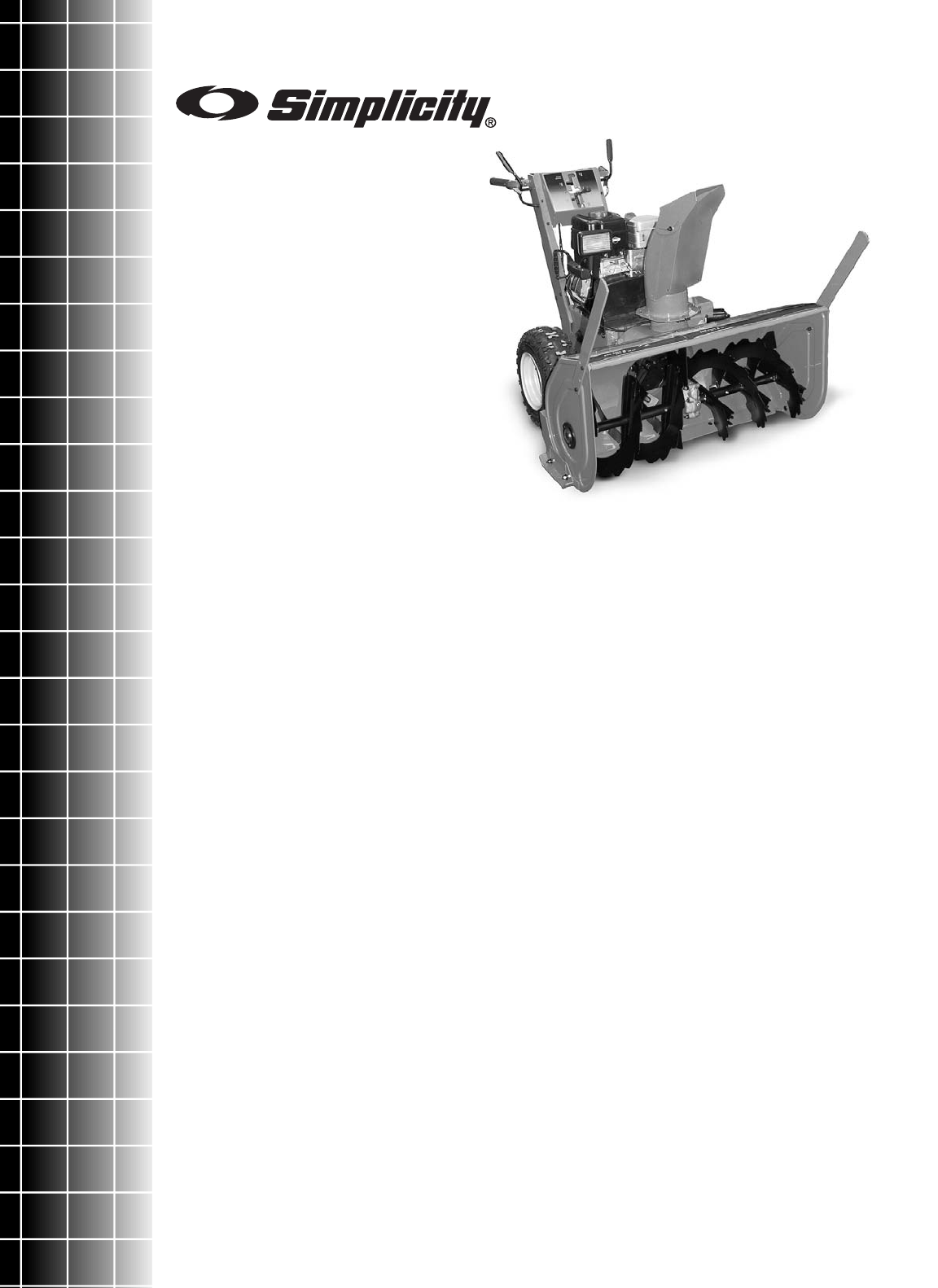
Parts Manual
Rev. 11/2005
Large Frame
Walk-Behind Snowthrowers
TP 400-4250-00-LW-S
Mf
g
. No. Descri
p
tion
9
.
5
HP
S
nowthrowers
1694867 9560E, 9.5HP Snowthrower
1694914 9560EX, 9.5HP Snowthrower (CE)
Mf
g
. No. Descri
p
tion
10.5HP Snowthrowers
1694847 10560E, 10.5HP Snowthrower
1694848 10560EX, 10.5HP Snowthrower (CE)
Mf
g
. No. Descri
p
tion
11.5HP Snowthrowers
1694849 11570E, 11.5HP Snowthrower
1694850 E11570, 11.5HP Snowthrower (CE)
Mf
g
. No. Descri
p
tion
1
3
HP
S
nowthrowers
1694851 1380E, 13HP Snowthrower
1694852 E1380, 13HP Snowthrower (CE)
1694872 1390E, 13HP SnowThrower
1694915 1390EX, 13HP SnowThrower (CE)
1732356
Part No.:

Table Of Content
s
Torque Specification Chart ..................................................................... Inside Back Cover
PRODUCT COMPONENTS PAGES
Handles and Controls Group - Channel .............................................................................................................. 4
Handles and Controls Group ............................................................................................................................... 8
Engine and Frame Group .................................................................................................................................... 12
Engine and Frame Group with Power Boost ....................................................................................................... 16
Auger and Impeller Group .................................................................................................................................... 20
Auger Housing and Chute Group - 24, 28 & 32 inch ........................................................................................... 24
Auger Housing and Chute Group - 38" Models ................................................................................................... 28
Traction Drive Group ............................................................................................................................................ 32
Wheels & Tires Group .......................................................................................................................................... 36
Decal Group ......................................................................................................................................................... 38
Headlight Group ................................................................................................................................................... 40
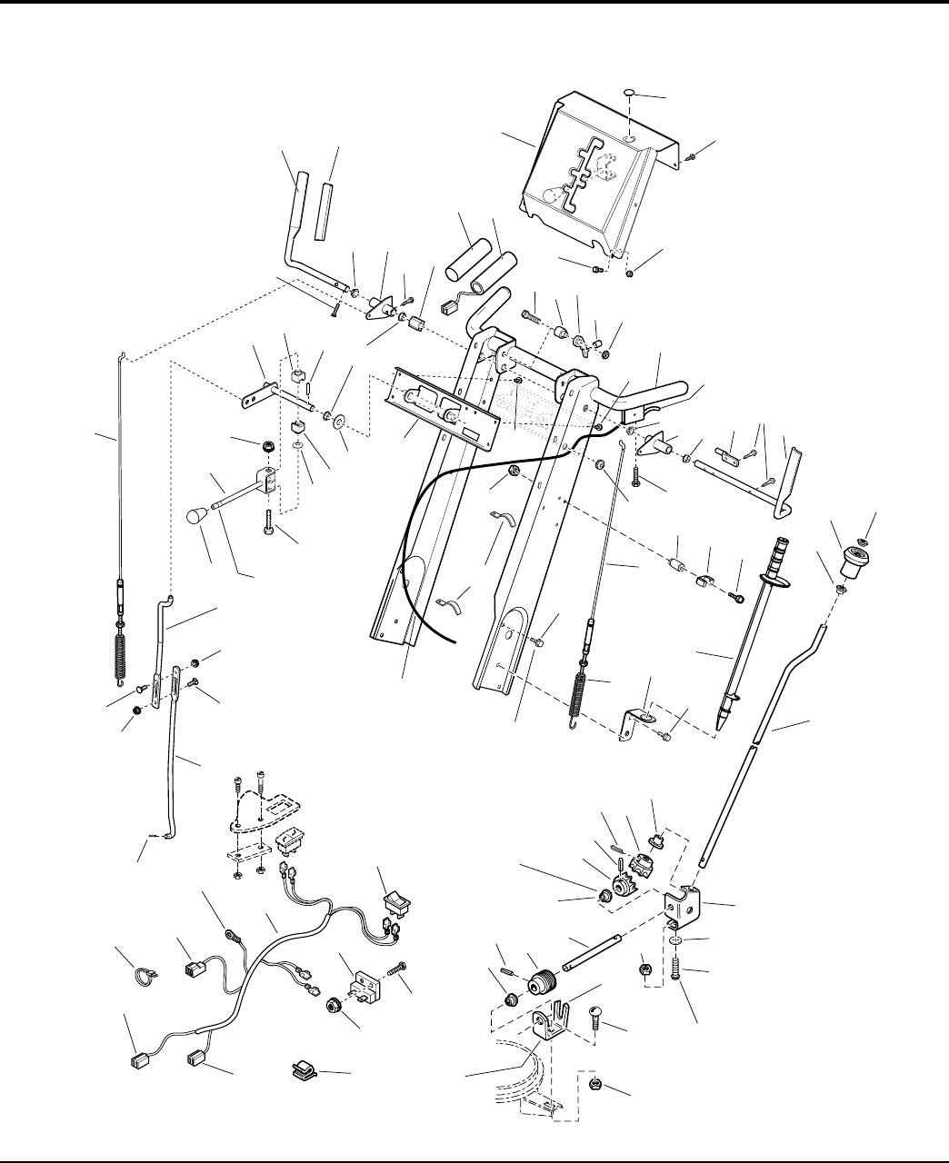
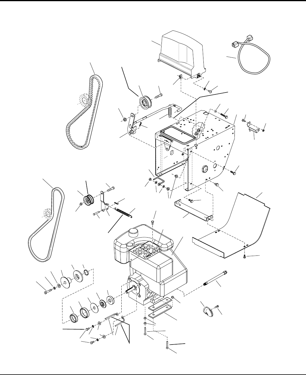
Handles and Controls Group - Channel
NOTE: Unless noted otherwise,
use the standard hardware torque
specification chart.
Linkage adjustment for traction and
auger drive with power boost: with
drive levers engaged, the bottom end of
lower rods (Ref. 40 & 66) should be flush
with bottom of springs (Ref. 39 & 68).
To engine
ground
Shift rod assembly
(Ref. 71) must pivot
freely on pivot blocks
(Ref. 21).
Torque to
19 - 29 ft-lbs.
Mount clutch cable
to cable support, see
Engine & Frame.
To engine
plug
To spout
motor
To headlight
See Auger Housing and
Chute Group - 38"
The holes in the frame for Ref. 51 are
slotted so the gear support (Ref. 45) can
be positioned to ensure the inside surface
of the gear support is tight against the
hub of the front gear (Ref. 50).
Mount bushings (Ref. 78)
with flange on inside of
brackets, 3 places.
Slot towards
rear of unit.
10
14 13
12
45
6
3
7
12
21
12
9
15 16 17
18 19
25
54
8
20
23 24
35
36
26
34
60
64
69
70
69
56
71
96
4
4
45
72
4
65
66
67
56
62 62
56
63
61
22
68
53
55
58
2727
57
56
11
34
33
29
30
31
32
45
38 37
40
41
39
42
50
49 48
44 47
42
46
43
39
39
52
51
44
39
28
12
59
987044
The above parts group applies to the following Mfg. Nos.:
2005 4
© Copyright Simplicity Manufacturing, Inc. All Rights Reserved.
1694847 - 10560E
1694848 - 10560EX
1694849 - 11570E
1694850 - E11570
1694851 - 1380E
1694852 - E1380
1694872 - 1390E
1694915 - 1390EX
TP 400-4250-00-LW-S

PART NO. DESCRIPTIONREF NO QTY.
Handles and Controls Group - Channel
Footnotes
1 1727128 1 HANDLE, Clutch R.H.
2 1668608 2 GRIP, Handle Clutch, Black
3 1928732 1 CAPSCREW, Hex Washer Head Taptite #10-24 x 1
4 1729104 5 BUSHING, 1/2 ID x 3/4 OD x 1/4, Plastic
5 1725205A 2 LEVER & TUBE ASSEMBLY, Clutch
6 1960471 4 CAPSCREW, Hex Washer Head Taptite #12-24 x 1
7 1705899 1 GUIDE, Control
8 1726317 2 GRIP, Black Soft 1 in. (24 in. & 28 in. Models Only)
9 1723965 2 HAND GRIP, Heated 1 in. (32 & 38 in. Models Only)
10 1667800C 1 DASHBOARD
11 1724489 1 PLUG, Button (38 in. Models Only)
12 1925592 6 CAPSCREW, Hex Washer Head Taptite 1/4-20 x 3/4
13 1930641 4 NUT, Hex Flange Whiz Lock 1/4-20
14 1935450 4 CAPSCREW, Hex Washer Head, 1/4-20 x 3/4 G5
15 1933689 1 CAPSCREW, Hex Flange Whiz Lock, 5/16-18 x 1-1/2
16 1678579 1 SPACER, 21/64 ID x 13/16 OD x 15/16
17 1705898 1 LATCH, Control
18 1701342 1 SPRING, Compression
19 1960686 1 NUT, Hex Flange 5/16-18 ESNA
20 1729855C 1 HANDLE ASSEMBLY, Channel
21 1723935A 1 BRACKET, Shift Control
22 1718791 1 CABLE & HANDLE ASSEMBLY, Clutch L.H.
23 1677453 1 ROD, Control 2 in. Flat
24 1727127 1 HANDLE, Clutch L.H.
25 1725702 1 SCREW, Pan Head Torx #10 x 1/2 Thick Cut
26 1664022 1 GROMMET, 1/2
27 2834683 1 CLIP, Wire
28 1933896 1 NUT, Hex Lock 10-24 with Nylon Insert NC3B (Quantity 3 used no 32 in. models)
29 1678392 1 SPACER, 17/64 ID x 3/8 OD x 21/64
30 1726728 1 CLIP, Clean Out Tool
31 1960589 1 SCREW, Phillips #10-24 x 3/4
32 7075909 1 TOOL, Clean Out
33 1726727A 1 BRACKET, Clean Out Tool
34 1960729 6 CAPSCREW, Hex Serrated Flange Tap, 5/16-18 x 1
35 1728115 1 CABLE ASSEMBLY, LH (Includes Ref. No. 36)
36 1707452 1 SPRING, Extension 3-11/32 Long
37 1960093 1 NUT, Push Pal (Used on all models Except 38 in. Models)
38 1714084 1 KNOB, Spinner, Soft (Used on all modles Except 38 in. Models)
39 1667588 4 BUSHING, 3/8 ID x 7/16 OD x 13/64, Nylon (Used on all models Except 38 in. Models)
40 1715658 1 ROD, Chute Control, 27 in. Long (Used on all models Except 38 in. Models)
41 1718793 1 SUPPORT, Gear (Used on all models Except 38 in. Models)
42 1718593 2 GEAR, Powered Metal (Used on all models Except 38 in. Models)
43 1918452 1 PIN, Cotter 1/8 x 1 (Used on all models Except 38 in. Models)
44 2816168 2 PIN, Spring 1/8 x 3/4 (Used on all models Except 38 in. Models)
The above parts group applies to the following Mfg. Nos.:
2005 5
© Copyright Simplicity Manufacturing, Inc. All Rights Reserved.
1694847 - 10560E
1694848 - 10560EX
1694849 - 11570E
1694850 - E11570
1694851 - 1380E
1694852 - E1380
1694872 - 1390E
1694915 - 1390EX
TP 400-4250-00-LW-S

Handles and Controls Group - Channel
NOTE: Unless noted otherwise,
use the standard hardware torque
specification chart.
Linkage adjustment for traction and
auger drive with power boost: with
drive levers engaged, the bottom end of
lower rods (Ref. 40 & 66) should be flush
with bottom of springs (Ref. 39 & 68).
To engine
ground
Shift rod assembly
(Ref. 71) must pivot
freely on pivot blocks
(Ref. 21).
Torque to
19 - 29 ft-lbs.
Mount clutch cable
to cable support, see
Engine & Frame.
To engine
plug
To spout
motor
To headlight
See Auger Housing and
Chute Group - 38"
The holes in the frame for Ref. 51 are
slotted so the gear support (Ref. 45) can
be positioned to ensure the inside surface
of the gear support is tight against the
hub of the front gear (Ref. 50).
Mount bushings (Ref. 78)
with flange on inside of
brackets, 3 places.
Slot towards
rear of unit.
10
14 13
12
45
6
3
7
12
21
12
9
15 16 17
18 19
25
54
8
20
23 24
35
36
26
34
60
64
69
70
69
56
71
96
4
4
45
72
4
65
66
67
56
62 62
56
63
61
22
68
53
55
58
2727
57
56
11
34
33
29
30
31
32
45
38 37
40
41
39
42
50
49 48
44 47
42
46
43
39
39
52
51
44
39
28
12
59
987044
The above parts group applies to the following Mfg. Nos.:
2005 6
© Copyright Simplicity Manufacturing, Inc. All Rights Reserved.
1694847 - 10560E
1694848 - 10560EX
1694849 - 11570E
1694850 - E11570
1694851 - 1380E
1694852 - E1380
1694872 - 1390E
1694915 - 1390EX
TP 400-4250-00-LW-S

PART NO. DESCRIPTIONREF NO QTY.
Handles and Controls Group - Channel
Footnotes
45 1960518 2 NUT, Push for 1/4 Diameter Thread
46 1960252 2 CARRIAGE BOLT, 1/4-20 x 5/8 G5 (Used on all models Except 38 in. Models)
47 1960294 2 NUT, Hex Flange Whiz Lock, 1/4-20 Small (Used on all models Except 38 in. Models)
48 1725283 1 ROD, Chute Worm, 18 Long (Used on all models Except 38 in. Models)
49 1668186 1 WORM, Chute, L.H. (Used on all models Except 38 in. Models)
50 1611911 1 SUPPORT, Worm (Used on all models Except 38 in. Models)
51 1931333 1 CARRIAGE BOLT, 5/16-18 x 3/4 G5 (Used on all models Except 38 in. Models)
52 1960684 1 NUT, Hex KEPS Conical Washer, 5/16-18 (Used on all models Except 38 in. Models)
53 1723967 1 SWITCH, Hand Warmer (32 & 38 in. Models Only)
54 1923341 1 CAPSCREW, Hex Head, 1/4-20 x 3/4 G5 (32 & 38 in. Models Only)
55 1724037 1 RESISTOR BLOCK, Male Terminal (32 & 38 in. Models Only)
56 1960685 4 NUT, Hex KEPS, 1/4-20 Conical Washer
57 2172434 1 CLIP, Wire (Spout Rotator Models Only)
58 1725439 1 HARNESS, Wiring (Handwarmer Models Only)
58 1728968 1 HARNESS, Wiring (Handwarmer & Spout Rotator Models Only)
59 2825094 3 TIE, Self Locking 7-5/16 (32 & 38 in. Models Only)
60 1722460 1 PIN, Quick
61 1666255 1 ROD, Lower Shift 15-21/64 Long
62 1931317 2 CARRIAGE BOLT, 1/4-20 x 3/4 G5
63 1726304 1 ROD, Upper Shift 11-3/8 Long
64 1728114 1 CABLE ASSEMBLY, RH
65 1713844 1 KNOB, Hole
66 1714120 1 ROD & CLEVIS ASSEMBLY, Shift
67 1960705 1 CAPSCREW, Hex Flange Whiz Lock 1/4-20 x 2-1/4
68 1668681 1 WASHER, Curved
69 1668524 2 BLOCK, Pivot, Powdered Metal
70 1924361 1 WASHER, 1/2
71 1674567 1 ROD & ARM ASSEMBLY, Pivot
72 1960074 1 CLIP, Hair Pin
The above parts group applies to the following Mfg. Nos.:
2005 7
© Copyright Simplicity Manufacturing, Inc. All Rights Reserved.
1694847 - 10560E
1694848 - 10560EX
1694849 - 11570E
1694850 - E11570
1694851 - 1380E
1694852 - E1380
1694872 - 1390E
1694915 - 1390EX
TP 400-4250-00-LW-S
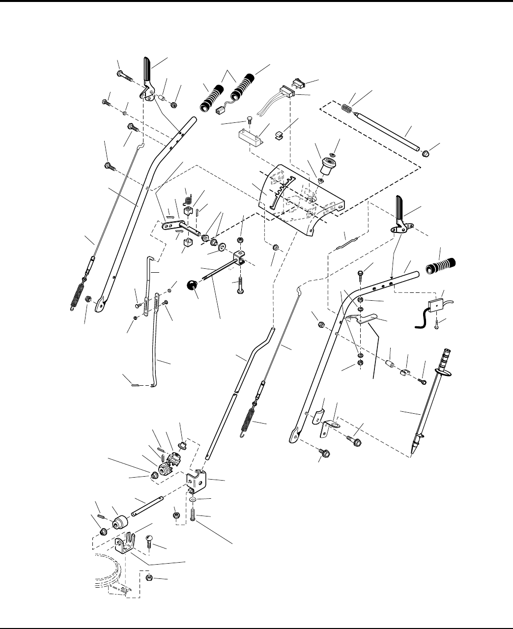
Handles and Controls Group
NOTE: Unless noted otherwise,
use the standard hardware torque
specification chart.
The holes in the frame for Ref. 48 are
slotted so the gear support (Ref. 46) can
be positioned to ensure the inside surface
of the gear support is tight against the
hub of the front gear (Ref. 56).
Mount bushings (Ref. 19)
with flange on inside of
brackets, 3 places.
Slot towards
rear of unit.
Shift rod assembly (Ref. 66)
must pivot freely on
pivot blocks, (Ref. 67).
Apply adhesive to
secure grips.
Insert shift rod (Ref. 65)
into outter hole of Ref. 68.
Must pivot freely
on capscrew (Ref 32).
Apply lubricant as required.
Must slide freely in
dash assembly (Ref 18).
Apply lubricant as required.
47
1
2
8
11
18
20 21
17
26
10
27
6
11
43
3
4
39
41
42
44
58 59
61
60
60
62
68
69 67
70
66
35
58
61
67
60
72
65
64
63
45
46
19
56
50
54 55
53 49
56
48
57
19
19
9
5
52
51
7
61
71
53
23
22
24
28
25
29
29
1630
32
19
33
34
40
13
14
15
16
35
36
37
31
38
12
52
987161
The above parts group applies to the following Mfg. Nos.:
2005 8
© Copyright Simplicity Manufacturing, Inc. All Rights Reserved.
1694867 - 9560E
1694914 - 9560EX
TP 400-4250-00-LW-S

PART NO. DESCRIPTIONREF NO QTY.
Handles and Controls Group
Footnotes
1 1726833 1 CABLE AND SPRING ASSEMBLY, R.H. Auger
2 1731334A 1 HANDLE, Tube, R.H.
3 1922127 1 CAPSCREW, Hex Head, 5/16-18 x 1-3/4 G5
4 1921221 3 CAPSCREW, Hex Head, 5/16-18 x 1-1/2 G5
5 1960671 2 SCREW, Pan Head Torx, 1/4-20 x 3/4, Thread Cutting
6 1715654 2 SPACER, 1/4ID x 25/64OD x 11/64LG
7 1922837 2 CAPSCREW, Hex Head, 1/4-20 x 1-1/2 G5
8 1722638 1 HANDLE, Clutch R.H.
9 1715655 2 SPACER
10 1923358 2 NUT, Hex Centerlock, 1/4-20
11 1726317 2 GRIP
12 1723965 2 HAND GRIP, Heated 1" Diameter
13 1923341 3 CAPSCREW, Hex Head 1/4-20 x 3/4 G5
14 1724037 1 RESISTOR BLOCK, 2 Male Terminal
15 1723967 1 SWITCH, Hand Warmer
16 1728968 1 HARNESS, Wiring
17 1715956 1 CLIP, Wire
18 1726983A 1 DASH AND SUPPORT ASSEMBLY, Tubular
19 1667588 4 BUSHING, 47/125ID x 437/1000OD x 1/5LG
20 1714084 1 KNOB, Spinner
21 1960093 1 NUT, Push Pal, 3/8" Diameter Stud Capped
22 1722690 1 SPRING, Complete
23 1722633 1 ROD AND SPRING ASSEMBLY, w/Pin (Includes Ref. No. 24)
24 1960519 1 PUSH NUT, Stud Cap, 1/2
25 1722630 1 ROD, 4/25" Diameter, E-Coat
26 1722667 1 HANDLE, Clutch L.H.
27 1731333A 1 HANDLE, Tube, L.H.
28 1960662 1 CAPSCREW, Hex Head, 1/4-20 x 2 G5
29 1920397 2 NUT, Hex Lock ESNA Light, 1/4-20NC-3B
30 1921319 2 WASHER, 1/4
31 1933896 1 NUT, Hex Lock, 10-24
32 1722631A 1 LEVER, Pivot
33 1718791 1 CABLE AND HANDLE ASSEMBLY, Clutch
34 1725702 1 SCREW, Pan Head Torx, #10 x 1/2 Thread Cut
35 1726995 1 SPACER, 1-1/4 LG Beveled End
36 1726728 1 CLIP, Snow Stick
37 1960727 1 SCREW, Hex Flange Slot, #10-24 x 2-1/2
38 7075909 1 STICK, Snow Removal
39 1720452 2 CLAMP, Saddle Snow Handle E-Coat
40 1726727A 1 BRACKET, Clean Out Tool
41 1960730 2 CAPSCREW, Hex Head Serrated Flange Taptite, 5/16-18 x 2 G5
42 1960729 1 CAPSCREW, Hex Whiz Lock Flange, 5/16-18 x 1
43 1726832 1 CABLE AND SPRING ASSEMBLY, L.H. Traction (Includes Ref. No. 44)
44 1707452 1 SPRING, Extension
The above parts group applies to the following Mfg. Nos.:
2005 9
© Copyright Simplicity Manufacturing, Inc. All Rights Reserved.
1694867 - 9560E
1694914 - 9560EX
TP 400-4250-00-LW-S

Handles and Controls Group
NOTE: Unless noted otherwise,
use the standard hardware torque
specification chart.
The holes in the frame for Ref. 48 are
slotted so the gear support (Ref. 46) can
be positioned to ensure the inside surface
of the gear support is tight against the
hub of the front gear (Ref. 56).
Mount bushings (Ref. 19)
with flange on inside of
brackets, 3 places.
Slot towards
rear of unit.
Shift rod assembly (Ref. 66)
must pivot freely on
pivot blocks, (Ref. 67).
Apply adhesive to
secure grips.
Insert shift rod (Ref. 65)
into outter hole of Ref. 68.
Must pivot freely
on capscrew (Ref 32).
Apply lubricant as required.
Must slide freely in
dash assembly (Ref 18).
Apply lubricant as required.
47
1
2
8
11
18
20 21
17
26
10
27
6
11
43
3
4
39
41
42
44
58 59
61
60
60
62
68
69 67
70
66
35
58
61
67
60
72
65
64
63
45
46
19
56
50
54 55
53 49
56
48
57
19
19
9
5
52
51
7
61
71
53
23
22
24
28
25
29
29
1630
32
19
33
34
40
13
14
15
16
35
36
37
31
38
12
52
987161
The above parts group applies to the following Mfg. Nos.:
2005 10
© Copyright Simplicity Manufacturing, Inc. All Rights Reserved.
1694867 - 9560E
1694914 - 9560EX
TP 400-4250-00-LW-S

PART NO. DESCRIPTIONREF NO QTY.
Handles and Controls Group
Footnotes
45 1727088 1 ROD, 3/8" Diameter, 26"LG, E-Coat
46 1718793 1 SUPPORT, Gear
47 1960518 2 NUT, Push for 1/4 Diameter Thread
48 1960252 2 CARRIAGE BOLT, 1/4-20 x 5/8 G5
49 1960294 2 NUT, Hex Flange, 1/4-20, Whiz Lock Small
50 1611911 1 SUPPORT, Worm
51 1931333 1 CARRIAGE BOLT, 5/16-18 x 3/4 G5
52 1960684 2 NUT, Hex Keps, 5/16-18, Conical Washer
53 2816168 2 PIN, Spring 1/8 x 3/4
54 1668186 1 WORM, Chute, L.H.
55 1725283 1 ROD, 3/8" Diameter, Chute Worm E-Coat
56 1718593 2 GEAR, Powdered Metal, Metafusion
57 1918452 1 PIN, Cotter 1/4 x 1
58 1722460 1 PIN, Quick
59 1666255 1 ROD, 3/4" Diameter
60 1960685 3 NUT, Hex KEPS, 1/4-20, Conical Washer
61 1931317 2 CARRIAGE BOLT, 1/4-20 x 3/4 G5
62 1726304 1 ROD, 3/4" Diameter, Shift Upper E-Coat, 11-19/50LG
63 1726734 1 KNOB, Intermediate Thread, 3/8-16
64 1960705 1 SCREW, Hex Whiz Lock Flange, 1/4-20 x 2-1/4
65 1668523 1 ROD AND CLEVIS ASSEMBLY, Shift, Threaded
66 1924361 1 WASHER, 1/2
67 1668524 2 BLOCK, Pivot, 3/4 x 3/4, Powdered Metal
68 1720240 1 ROD AND ARM ASSEMBLY, Pivot
69 1715123 1 SPRING, Torsion
70 1960074 1 CLIP, Hair Pin
71 1668185 2 BUSHING, 1/2ID x 3/4OD x 1/4LG
72 1960686 4 NUT, Hex Flange, 5/16-18 ESNA
The above parts group applies to the following Mfg. Nos.:
2005 11
© Copyright Simplicity Manufacturing, Inc. All Rights Reserved.
1694867 - 9560E
1694914 - 9560EX
TP 400-4250-00-LW-S
Engine and Frame Group
NOTE: Unless noted otherwise,
use the standard hardware torque
specification chart.
Hook one end of spring (Ref. 7)
into top hole of roller arm (Ref. 6)
and other end into top hole of the idler
arm assembly in the Traction Drive Group.
Long hub of idler
pulley (Ref. 3) to
be toward idler
arm (Ref. 6).
Position idler pulley (Ref. 12)
at center of slot in clutch arm
(Ref. 10).
Hook one end of spring (Ref. 14)
over clutch rod assembly (Ref. 10)
between tabs and other end onto
the tube handle capscrew (Ref. 20).
Torque (4) Engine
Bolts to 17 - 21 ft. lbs.
or 23 - 29 N m
Torque to
10-14 ft. lbs. or
14-20 N m
Right rear bolt.
1
9
15
16
17
18
21
20
25
26
27
28
29
1430
7
6
5
2
3
4
8
8
10
11
12 13
14
39
29
48 49 50
25
37
19
22
24
23
38
40
37
41
45
46
47
3542
3543
3544
31
32
34
36
35
33
987035
The above parts group applies to the following Mfg. Nos.:
2005 12
© Copyright Simplicity Manufacturing, Inc. All Rights Reserved.
1694867 - 9560E
1694914 - 9560EX
TP 400-4250-00-LW-S

PART NO. DESCRIPTIONREF NO QTY.
Engine and Frame Group
Footnotes
1 1700415 1 MV-BELT, 3L
2 1928731 1 NUT, Hex, Toplock, Jam, 3/8-16
3 1668477 4 PULLEY, Idler
4 1960647 1 SCREW, Hex Head, 3/8-16 x 1-1/2
5 1665994 1 PIN, Flat Head Drilled
6 1703046A 1 ARM, Idler, 5-3/4 LG
7 1727149 1 SPRING, Extension
8 1722460 2 PIN, Quick
9 1701257 1 V-BELT, HA
10 1729646A 1 ROD AND ARM ASSEMBLY, Clutch, Brake
11 1928352 1 NUT, Hex Flange, 3/8-16 Whiz Lock Large
12 1726348 1 PULLEY, Idler
13 2860709 1 CAPSCREW, Hex Whiz Lock Flange, 3/8-16 x 1-3/4
14 2159106 1 SPRING, Extension, 4-1/4 Long
15 1725287 1 COVER, Belt
16 1935255 2 NUT, Speed, 5/16-18, Lug Type
17 2820426 2 LOCKWASHER, External Tooth, 5/16
18 1918249 2 SCREW, Truss head Slotted, 5/16-18 x 3/4
19 1724064 1 CORD, Electric Extension
20 1921221 1 CAPSCREW, Hex Head, 5/16-18 x 1-1/2 G5
21 1726568C 1 FRAME ASSEMBLY, Chain/Tube Handles
22 1931317 2 CARRIAGE BOLT, 1/4-20 x 3/4 G5
23 1960685 2 NUT, Hex KEPS, 1/4-20, Conical Washer
24 1720404A 1 SUPPORT, Clutch Cable, 16GA
25 1930591 4 SCREW, Hex Whiz Lock Flange, 5/16-18 x 3/4
26 1664847 4 CAPSCREW, Hex Washer Head Taptite, 5/16-18 x 3/4
27 1726870C 1 COVER, Bottom Frame, 20GA
28 1925003 2 SCREW, Hex Washer Head Taptite, 1/4-20 x 1/2
29 1727004A 1 SUPPORT, Tie Bar
30 1927557 4 NUT, Hex Flange, 5/16-18, Whiz Lock Large
31 1929477 3 SCREW, Hex Washer Head Taptite, #10-24 x 1/2
32 1725664A 1 GUARD, Muffler, 18GA
33 * 1 ENGINE, 9.5HP B&S Electric Start Engine Model: 20A414 Engine Type: 0111E1
33 * 1 ENGINE, 9.5HP B&S Electric Start Engine (CE Models) Model: 20A414 Engine Type:
0113E1
34 1726942 1 HOSE, Oil Drain, w/Fittings
35 1727033 1 SCREW, Muffler Deflector
36 1727032 1 DEFLECTOR, Rain Guard, B&S Snow Muffler
37 2831277 4 NUT, Hex Flange, 5/16-18, Whiz Lock Small
38 1725326A 4 SUPPORT, Engine Riser, 3/8" Thick, 1-1/4 x 4-31/50
39 1935159 3 CAPSCREW, Hex Whiz Lock Flange, 5/16-18 x 2-1/4
40 2821719 1 CAPSCREW, Hex Head, 5/16-18 x 2-1/2 G5
41 1727785 1 STOP, Belt
42 1919326 2 WASHER, 5/16
43 1917356 2 LOCKWASHER, Spring, 5/16
* See your local Briggs & Stratton distributor for Parts & Service.
The above parts group applies to the following Mfg. Nos.:
2005 13
© Copyright Simplicity Manufacturing, Inc. All Rights Reserved.
1694867 - 9560E
1694914 - 9560EX
TP 400-4250-00-LW-S

Engine and Frame Group
NOTE: Unless noted otherwise,
use the standard hardware torque
specification chart.
Hook one end of spring (Ref. 7)
into top hole of roller arm (Ref. 6)
and other end into top hole of the idler
arm assembly in the Traction Drive Group.
Long hub of idler
pulley (Ref. 3) to
be toward idler
arm (Ref. 6).
Position idler pulley (Ref. 12)
at center of slot in clutch arm
(Ref. 10).
Hook one end of spring (Ref. 14)
over clutch rod assembly (Ref. 10)
between tabs and other end onto
the tube handle capscrew (Ref. 20).
Torque (4) Engine
Bolts to 17 - 21 ft. lbs.
or 23 - 29 N m
Torque to
10-14 ft. lbs. or
14-20 N m
Right rear bolt.
1
9
15
16
17
18
21
20
25
26
27
28
29
1430
7
6
5
2
3
4
8
8
10
11
12 13
14
39
29
48 49 50
25
37
19
22
24
23
38
40
37
41
45
46
47
3542
3543
3544
31
32
34
36
35
33
987035
The above parts group applies to the following Mfg. Nos.:
2005 14
© Copyright Simplicity Manufacturing, Inc. All Rights Reserved.
1694867 - 9560E
1694914 - 9560EX
TP 400-4250-00-LW-S

PART NO. DESCRIPTIONREF NO QTY.
Engine and Frame Group
Footnotes
44 1921515 2 CAPSCREW, Hex Head, 5/16-24 x 3/4 G5
45 1922128 1 CAPSCREW, Hex Head, 3/8-24 x 1-1/2 G8
46 1916965 1 LOCKWASHER, Spring, 3/8
47 1922755 1 WASHER, 3/8
48 1726867 1 PULLEY, Engine Outside, Powdered Metal
49 1726866 1 PULLEY, Engine Middle, Powdered Metal
50 1726865 1 PULLEY, Half Powdered Metal
* See your local Briggs & Stratton distributor for Parts & Service.
The above parts group applies to the following Mfg. Nos.:
2005 15
© Copyright Simplicity Manufacturing, Inc. All Rights Reserved.
1694867 - 9560E
1694914 - 9560EX
TP 400-4250-00-LW-S

Engine and Frame Group with Power Boost
NOTE: Unless noted otherwise,
use the standard hardware torque
specification chart.
Hook one end of spring (Ref. 7)
into top hole of roller arm (Ref. 6)
and other end into top hole of
the idler arm assembly in the
Traction Drive Group.
Long hub of idler
pulley (Ref. 3) to
be toward idler
arm (Ref. 6).
Position idler pulley (Ref. 12)
at center of slot in clutch arm
(Ref. 10).
Hook one end of spring (Ref. 14)
over clutch rod assembly (Ref. 10)
between tabs and other end into
slot in frame.
Torque (4) Engine
Bolts to 17 - 21 ft. lbs.
or 23 - 29 N m
Torque to
10-14 ft. lbs. or
14-20 N m Right rear bolt.
Position belt stops 1/16 - 1/8
from belt when auger clutch is engaged.
1
9
15
16
17
18
22
21
26
28
29
30
1431
7
6
5
2
3
4
8
8
10
11
12 13
14
43
29
51
52 53
27
41
19
21
20
23
25
24
42
44
41
45
54
55
56
3546
3547
3548
35
36
38
40
39
37
45
50
49
1432
34
33
59
58
57
987038
The above parts group applies to the following Mfg. Nos.:
2005 16
© Copyright Simplicity Manufacturing, Inc. All Rights Reserved.
1694847 - 10560E
1694848 - 10560EX
1694849 - 11570E
1694850 - E11570
1694851 - 1380E
1694852 - E1380
1694872 - 1390E
1694915 - 1390EX
TP 400-4250-00-LW-S

PART NO. DESCRIPTIONREF NO QTY.
Engine and Frame Group with Power Boost
Footnotes
1 1700415 1 V-BELT, 3L
1 1672732 1 V-BELT, 3L (Used Only on 38 in. Models)
2 1928731 1 NUT, Hex, Toplock, Jam, 3/8-16
3 1668477 1 PULLEY, Idler
4 1960647 1 CAPSCREW, Hex Head, 3/8-16 x 1-1/2
5 1665994 1 PIN, Flat Head Drilled
6 1703046A 2 ARM, Idler, 5-3/4 LG
7 1727149 1 SPRING, Extension
8 1722460 1 PIN, Quick
9 1676460 1 V-BELT, HA
9 1666655 1 V-BELT, HA (Used Only on 38 in. Models)
10 1729646A 1 ROD AND ARM ASSEMBLY, Clutch Brake
11 1928352 1 NUT, Hex Flange, 3/8-16 Whiz Lock Large
12 1726348 1 PULLEY, Idler
13 2860709 1 CAPSCREW, Hex Whiz Lock Flange, 3/8-16 x 1-3/4
14 2159106 1 SPRING, Extension
15 1725287 1 COVER, Belt
16 1935255 2 NUT, Speed, 5/16-18, Lug Type
17 2820426 2 LOCKWASHER, External Tooth, 5/16
18 1918249 2 SCREW, Truss head Slotted, 5/16-18 x 3/4
19 1724064 1 CORD, Electric Extension
20 1666697 1 SPACER
21 1930591 4 CAPSCREW, Hex Whiz Lock Flange, 5/16-18 x 3/4
22 1726568C 1 FRAME ASSEMBLY, Chain/Tube Handles
23 1931317 2 CARRIAGE BOLT, 1/4-20 x 3/4 G5
24 1960685 2 NUT, Hex KEPS, 1/4-20, Conical Washer
25 1720404A 1 SUPPORT, Clutch Cable, 16GA
26 1664847 4 CAPSCREW, Hex Washer Head Taptite, 5/16-18 x 3/4
27 1930595 4 CAPSCREW, Hex Whiz, 31/100-18 x 1-1/4
28 1726870C 1 COVER, Bottom Frame, 20GA
29 1925003 2 CAPSCREW, Hex Washer Head Taptite, 1/4-20 x 1/2
30 1727004A 1 SUPPORT, Tie Bar
31 1927557 4 NUT, Hex Flange, 5/16-18, Whiz Lock Large
32 1919326 1 WASHER, Flat, 11/32 x 3/4 x 1/16
33 1923362 1 NUT, Hex Centerlock, 5/16-18
34 1702969 1 BELT STOP
35 1929477 3 CAPSCREW, Hex Washer Head Taptite, #10-24 x 1/2
36 1725664A 1 GUARD, Muffler, 18GA
37 * 1 ENGINE, 10.5HP B&S Electric Start Model: 20E214 Type: 0110E1
37 * 1 ENGINE, 10.5HP B&S Electric Start (CE) Model: 20E214 Type: 0359E1
37 * 1 ENGINE, 11.5HP B&S Electric Start Model: 21C214 Type: 0110E1
37 * 1 ENGINE, 11.5HP B&S Electric Start (CE) Model: 21C216 Type: 0131E1
37 * 1 ENGINE, 13HP B&S Electric Start Model: 21A414 Type: 0112E1
37 * 1 ENGINE, 13HP B&S Electric Start (CE) Model: 21A414 Type: 0215E1
* See your local Briggs & Stratton distributor for Parts & Service.
The above parts group applies to the following Mfg. Nos.:
2005 17
© Copyright Simplicity Manufacturing, Inc. All Rights Reserved.
1694847 - 10560E
1694848 - 10560EX
1694849 - 11570E
1694850 - E11570
1694851 - 1380E
1694852 - E1380
1694872 - 1390E
1694915 - 1390EX
TP 400-4250-00-LW-S
Engine and Frame Group with Power Boost
NOTE: Unless noted otherwise,
use the standard hardware torque
specification chart.
Hook one end of spring (Ref. 7)
into top hole of roller arm (Ref. 6)
and other end into top hole of
the idler arm assembly in the
Traction Drive Group.
Long hub of idler
pulley (Ref. 3) to
be toward idler
arm (Ref. 6).
Position idler pulley (Ref. 12)
at center of slot in clutch arm
(Ref. 10).
Hook one end of spring (Ref. 14)
over clutch rod assembly (Ref. 10)
between tabs and other end into
slot in frame.
Torque (4) Engine
Bolts to 17 - 21 ft. lbs.
or 23 - 29 N m
Torque to
10-14 ft. lbs. or
14-20 N m Right rear bolt.
Position belt stops 1/16 - 1/8
from belt when auger clutch is engaged.
1
9
15
16
17
18
22
21
26
28
29
30
1431
7
6
5
2
3
4
8
8
10
11
12 13
14
43
29
51
52 53
27
41
19
21
20
23
25
24
42
44
41
45
54
55
56
3546
3547
3548
35
36
38
40
39
37
45
50
49
1432
34
33
59
58
57
987038
The above parts group applies to the following Mfg. Nos.:
2005 18
© Copyright Simplicity Manufacturing, Inc. All Rights Reserved.
1694847 - 10560E
1694848 - 10560EX
1694849 - 11570E
1694850 - E11570
1694851 - 1380E
1694852 - E1380
1694872 - 1390E
1694915 - 1390EX
TP 400-4250-00-LW-S

PART NO. DESCRIPTIONREF NO QTY.
Engine and Frame Group with Power Boost
Footnotes
38 1726942 1 HOSE, Oil Drain, w/Fittings
39 1727033 1 CAPSCREW, Muffler Deflector
40 1727032 1 DEFLECTOR, Rain Guard, B&S Snow Muffler
41 2831277 4 NUT, Hex Flange, 5/16-18, Whiz Lock Small
42 1725326A 4 SUPPORT, Engine Riser (Used on all models Except 38 in. Models)
43 1935159 3 CAPSCREW, Hex Whiz Lock Flange, 5/16-18 x 2-1/4 (Used on all models Except 38
in. Models)
43 1921221 3 CAPSCREW, Hex Head, 5/16-18 x 1-1/2 G5 (Used Only on 38 in. Models)
44 2821719 1 CAPSCREW, Hex Head, 5/16-18 x 2-1/2 G5 (Used on all models Except 38 in.
Models)
44 2822127 1 CAPSCREW, Hex Head 5/16-18 x 1-3/4 G5 (Used Only on 38 in. Models)
45 1731178 1 STOP, Belt
46 1919326 2 WASHER, 5/16
47 1917356 2 LOCKWASHER, Spring, 5/16
48 1921515 2 CAPSCREW, Hex Head, 5/16-24 x 3/4 G5
49 1701849 1 SPRING, Compression
50 1702425 1 SPRING, Compression
51 1701818 1 WASHER, Thrust
52 1726869 1 PULLEY HALF, Middle
53 1726868 1 PULLEY HALF, Inside
54 1922128 1 CAPSCREW, Hex Head, 3/8-24 x 1-1/2 G8
55 1916965 1 LOCKWASHER, Spring, 3/8
56 1922755 1 WASHER, 3/8
57 1726864 1 PULLEY HALF, Outside
58 1726863 1 PULLEY HALF, Middle
59 1701825 1 WICK, Felt, Oil
* See your local Briggs & Stratton distributor for Parts & Service.
The above parts group applies to the following Mfg. Nos.:
2005 19
© Copyright Simplicity Manufacturing, Inc. All Rights Reserved.
1694847 - 10560E
1694848 - 10560EX
1694849 - 11570E
1694850 - E11570
1694851 - 1380E
1694852 - E1380
1694872 - 1390E
1694915 - 1390EX
TP 400-4250-00-LW-S

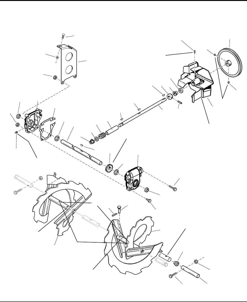
Auger and Impeller Group
NOTE: Unless noted otherwise,
use the standard hardware torque
specification chart.
37
End of hub to be flush
with end of rolled down
shaft (Ref. 9).
Torque to 30 -34 ft-lbs.
40 - 46 Nm.
Impeller to be positioned
against bearing before
tightening set screw.
Marked side of worm
gear must contact against
left thrust washer to assure
proper gear mesh.
Auger assembly
stamped "R".
Auger assembly
stamped "L".
Torque to
18-21 ft-lbs.
24 - 28 Nm.
Apply grease until
it appears at ends
of auger assembly
(2 places).
Torque to 9 - 11 ft-lbs.
12- 15 Nm.
38" Models only.
1
2
3
4
5
6
7
8
9
10
12
13
14
15
16
17
18
19
20 21 22
30
24
25
28
27
2
10
10
6
26
14
18
11
2929
33
32
31
34
36
35
15
23
985466R1
The above parts group applies to the following Mfg. Nos.:
2005 20
© Copyright Simplicity Manufacturing, Inc. All Rights Reserved.
1694847 - 10560E
1694848 - 10560EX
1694849 - 11570E
1694850 - E11570
1694851 - 1380E
1694852 - E1380
1694867 - 9560E
1694872 - 1390E
1694914 - 9560EX
1694915 - 1390EX
TP 400-4250-00-LW-S

PART NO. DESCRIPTIONREF NO QTY.
Auger and Impeller Group
Footnotes
1 1679293 1 PULLEY, w/Hub
2 1928721 2 SCREW, Set Square Head Cup Point, 5/16-18 x 1/2 G8
3 1612187A 1 IMPELLER ASSEMBLY
4 1960474 1 SCREW, Set Square Head Cup Point, 3/8-16 x 1/2 G8
5 1612093 1 SEAL, Oil 1/4" Thick
6 1612149 2 BUSHING, 377/500 ID x 1-1/10 OD x 1-1/100 LG Powerdered Metal
7 1612127 1 COLLAR, Thrust 3/4 LG
8 2836098 1 PIN, Drive Lock Type A 3/16 x 1-1/2
9 1612129 1 SHAFT, Worm 18-1/10 LG
10 2818312 3 KEY, Woodruff, 47/250 x 5/8
11 1612111 1 TUBE, 9/10 OD 39/50 ID, 7-1/2 LG
12 1612142 1 GEAR, Worm 1-3/8 LG
13 2168111 1 WASHER, Thrust
14 2118118 2 SEAL, Oil, 1/4" Thick
15 1930642 8 NUT, Hex Flange, 1/4-20 Toplock Small (Uses Quantity of 6 on 28 adn 38 in. Models)
16 1612137 1 CASE, Gear R.H.
17 1612124 1 GASKET, Gear Case
18 2118315 2 WASHER, Thrust
19 1731916 1 SHAFT, 16 LG Auger 3 Holes
20 2830246 1 KEY, Woodruff 1/4 x 3/4
21 1612141 1 GEAR, Worm 7/8 LG
22 1612136 1 CASE, Gear L.H.
23 1923282 2 CAPSCREW, Hex Head, 1/4-20 x 2-1/2 G5 (Used on 32 and 38 in. Modles)
24 1960346 8 CAPSCREW, Hex Head, 1/4-20 x 2-1/4 G5 (Uses Quantity of 6 on 28 adn 38 in.
Models)
25 1668344 2 PIN, Flat Head Drilled
26 1918447 2 PIN, Cotter 47/50 x 3/4
27 1718782A 1 AUGER ASSEMBLY, L.H. 9-1/2 LG (Used on 24 in. Models)
27 1718784A 1 AUGER ASSEMBLY, L.H. 11-1/2 LG (Used on 28 in. Models)
27 1718786A 1 AUGER ASSEMBLY, L.H. 13-1/2 LG (Used on 32 in. Models)
27 1723945A 1 AUGER ASSEMBLY, L.H. 15-9/10 LG (without Burshing) (Used on 38 in. Models)
27 1731322A 1 AUGER ASSEMBLY, L.H. 15-9/10 LG (Includes Ref. No. 37) (Used on 38 in. Models)
28 1718783A 1 AUGER ASSEMBLY, R.H. 9-1/2 LG (Used on 24 in. Models)
28 1718785A 1 AUGER ASSEMBLY, R.H. 11-1/2 LG (Used on 28 in. Models)
28 1718787A 1 AUGER ASSEMBLY, R.H. 13-1/2 LG (Used on 32 in. Models)
28 1723944A 1 AUGER ASSEMBLY, R.H. 15-9/10 LG (without Bushing) (Used on 38 in. Models)
28 1721321A 1 AUGER ASSEMBLY, R.H. 15-9/10 LG (Includes Ref. No. 37) (Used on 38 in. Models)
29 2821133 2 FITTING, Lube 1/4 Drive, No Check Ball
30 1668971 1 FITTING, Pipe Plug, Square Head
31 1921962 2 CAPSCREW, Hex Head, 1/4-20 x 1-3/4 G5 (Used on 38 in. Models)
32 1723931 2 SHAFT, E-Coat, 5 LG (Used on 38 in. Models)
33 1920397 2 NUT, Hex Lock ESNA Light, 1/4-20NC-3B (Used on 38 in. Models)
34 1931277 2 NUT, Hex Flange, 5/16-18, Whiz Lock Small (Used on 32 and 38 in. Models)
35 1931333 2 CARRIAGE BOLT, 5/16-18 x 3/4 G5 (Used on 32 and 38 in. Models)
36 1723922A 1 SUPPORT, Gear Box 10GA (Used on 38 in. Models)
The above parts group applies to the following Mfg. Nos.:
2005 21
© Copyright Simplicity Manufacturing, Inc. All Rights Reserved.
1694847 - 10560E
1694848 - 10560EX
1694849 - 11570E
1694850 - E11570
1694851 - 1380E
1694852 - E1380
1694867 - 9560E
1694872 - 1390E
1694914 - 9560EX
1694915 - 1390EX
TP 400-4250-00-LW-S
Auger and Impeller Group
NOTE: Unless noted otherwise,
use the standard hardware torque
specification chart.
37
End of hub to be flush
with end of rolled down
shaft (Ref. 9).
Torque to 30 -34 ft-lbs.
40 - 46 Nm.
Impeller to be positioned
against bearing before
tightening set screw.
Marked side of worm
gear must contact against
left thrust washer to assure
proper gear mesh.
Auger assembly
stamped "R".
Auger assembly
stamped "L".
Torque to
18-21 ft-lbs.
24 - 28 Nm.
Apply grease until
it appears at ends
of auger assembly
(2 places).
Torque to 9 - 11 ft-lbs.
12- 15 Nm.
38" Models only.
1
2
3
4
5
6
7
8
9
10
12
13
14
15
16
17
18
19
20 21 22
30
24
25
28
27
2
10
10
6
26
14
18
11
2929
33
32
31
34
36
35
15
23
985466R1
The above parts group applies to the following Mfg. Nos.:
2005 22
© Copyright Simplicity Manufacturing, Inc. All Rights Reserved.
1694847 - 10560E
1694848 - 10560EX
1694849 - 11570E
1694850 - E11570
1694851 - 1380E
1694852 - E1380
1694867 - 9560E
1694872 - 1390E
1694914 - 9560EX
1694915 - 1390EX
TP 400-4250-00-LW-S

PART NO. DESCRIPTIONREF NO QTY.
Auger and Impeller Group
Footnotes
37 1709894 2 BUSHING, Plastic (Used on 38 in. Models)
The above parts group applies to the following Mfg. Nos.:
2005 23
© Copyright Simplicity Manufacturing, Inc. All Rights Reserved.
1694847 - 10560E
1694848 - 10560EX
1694849 - 11570E
1694850 - E11570
1694851 - 1380E
1694852 - E1380
1694867 - 9560E
1694872 - 1390E
1694914 - 9560EX
1694915 - 1390EX
TP 400-4250-00-LW-S
Auger Housing and Chute Group - 24, 28 & 32 inch
NOTE: Unless noted otherwise,
use the standard hardware torque
specification chart.
Coat top and bottom of
chute ring with grease.
Scraper blade should
be on inside of housing.
When installing cable,
make sure it does not
come into contact with
muffler.
Plastic washer
(Ref. 2) goes
between chute
and deflector.
Mount cable bracket (Ref. 22)
on right hand side of handle
using shift control bracket
hardware.
Decal must cover
gap at hinge pivot.
muffler.
and deflector.
1
3
5
6
13
14
17
15
16
18
22
20
21
8
9
10
27
23
24
25
26
29 30
31
32
33
34
35
38
37 36
40
41
7
19
42
2
28
4
14
12
252511
39
987028
The above parts group applies to the following Mfg. Nos.:
2005 24
© Copyright Simplicity Manufacturing, Inc. All Rights Reserved.
1694847 - 10560E
1694848 - 10560EX
1694849 - 11570E
1694850 - E11570
1694851 - 1380E
1694852 - E1380
1694867 - 9560E
1694914 - 9560EX
TP 400-4250-00-LW-S

PART NO. DESCRIPTIONREF NO QTY.
Auger Housing and Chute Group - 24, 28 & 32 inch
Footnotes
1 1931333 1 CARRIAGE BOLT, 5/16-18 x 3/4 G5
2 2860210 1 WASHER, Nylon
4 1960686 1 NUT, Hex Flange ESNA Light, 5/16-18 (Used on all models Except 24 in. Models)
5 1670578 1 KNOB, Internal Thread, 5/16 (Used Only on 24 in. Models)
6 1704161C 1 CHUTE AND DEFLECTOR ASSEMBLY, Manual (Used Only on 24 in. Models)
6 1720671C 1 CHUTE AND DEFLECTOR ASSEMBLY, w/Remote (Used on all models Except 24 in.
Models)
7 1706085 2 DECAL, Orange Strip
8 1960001 3 SCREW, Hex Washer Head Pastite, 10-14 x 5/8
9 1667865 3 SPRING, Flat
10 1666613 3 HOLD DOWN, Chute
11 1702219 3 SPACER, 17/64 ID x 3/8 OD
12 1960126 2 NUT, Push 1/4
13 1611945 1 ROD, Spring
14 1611939 1 SPRING, Compression
15 2825094 1 TIE, Self Locking (Used on all models Except 24 in. Models)
16 1720446 1 CABLE AND KNOB ASSEMBLY, Chute (Includes Ref. No. 17, 18, 19, 20 & 21)
17 1611989 1 BOOT, Bellows
18 1719140 1 COLLET
19 1719139 1 SEAL, Rod
20 1719138 1 KNOB
21 1960600 1 SCREW, 8-32
22 1726411A 1 BRACKET, Cable
23 1960738 3 CAPSCREW, Hex Head, 5/16-18 x 5/8 G5
25 1665982A 1 RETAINER, Bearing
26 1729578 1 BEARING, Ball
27 1930659 3 NUT, Retainer Speed, 5/16-18
28 1663189 2 SPACER, Low
29 1665980 1 BEARING, Flange
30 1668639C 2 CAP, Bearing, 3-3/4OD
31 1923325 6 CAPSCREW, Hex Head 5/16-18 x 7/8 G5
32 1960687 6 NUT, Hex Flange 3/8-16 ESNA
33 1727854C 2 SKID SHOE, Reversible
34 1709946A 1 BLADE, Scraper, 24 in.
34 1709947A 1 BLADE, Scraper, 28 in.
34 1709948A 1 BLADE, Scraper, 32 in.
35 1935048 5 NUT, Hex Flange, 5/16-18, Two-Way Lock GA (Quantity 7 Only on 32 in. Models)
36 1960711 4 CARRIAGE BOLT, 3/8-16 x 3/4
37 1931277 6 NUT, Hex Flange, 5/16-18
38 1960699 5 CARRIAGE BOLT, 5/16-18 x 5/8 G5 (Quantity 7 Only on 32 in. Models)
39 1960684 4 NUT, Hex Keps, 5/16-18, Conical Washer (Used on all models Except 24 in. Models)
40 1664847 2 CAPSCREW, Hex Head, 5/16-18 x 3/4 G5 (Used on all models Except 24 in. Models)
41 1729642C 2 CUTTER, Drift, 1/4 in. Thick, 20LG (Used on all models Except 24 in. Models)
The above parts group applies to the following Mfg. Nos.:
2005 25
© Copyright Simplicity Manufacturing, Inc. All Rights Reserved.
1694847 - 10560E
1694848 - 10560EX
1694849 - 11570E
1694850 - E11570
1694851 - 1380E
1694852 - E1380
1694867 - 9560E
1694914 - 9560EX
TP 400-4250-00-LW-S

Auger Housing and Chute Group - 24, 28 & 32 inch
NOTE: Unless noted otherwise,
use the standard hardware torque
specification chart.
Coat top and bottom of
chute ring with grease.
Scraper blade should
be on inside of housing.
When installing cable,
make sure it does not
come into contact with
muffler.
Plastic washer
(Ref. 2) goes
between chute
and deflector.
Mount cable bracket (Ref. 22)
on right hand side of handle
using shift control bracket
hardware.
Decal must cover
gap at hinge pivot.
muffler.
and deflector.
1
3
5
6
13
14
17
15
16
18
22
20
21
8
9
10
27
23
24
25
26
29 30
31
32
33
34
35
38
37 36
40
41
7
19
42
2
28
4
14
12
252511
39
987028
The above parts group applies to the following Mfg. Nos.:
2005 26
© Copyright Simplicity Manufacturing, Inc. All Rights Reserved.
1694847 - 10560E
1694848 - 10560EX
1694849 - 11570E
1694850 - E11570
1694851 - 1380E
1694852 - E1380
1694867 - 9560E
1694914 - 9560EX
TP 400-4250-00-LW-S

PART NO. DESCRIPTIONREF NO QTY.
Auger Housing and Chute Group - 24, 28 & 32 inch
Footnotes
42 1729724C 1 HOUSING AND IMPELLER ASSEMBLY, 24 in.
42 1729726C 1 HOUSING AND IMPELLER ASSEMBLY, 28 in.
42 1729728C 1 HOUSING AND IMPELLER ASSEMBLY, 32 in.
The above parts group applies to the following Mfg. Nos.:
2005 27
© Copyright Simplicity Manufacturing, Inc. All Rights Reserved.
1694847 - 10560E
1694848 - 10560EX
1694849 - 11570E
1694850 - E11570
1694851 - 1380E
1694852 - E1380
1694867 - 9560E
1694914 - 9560EX
TP 400-4250-00-LW-S

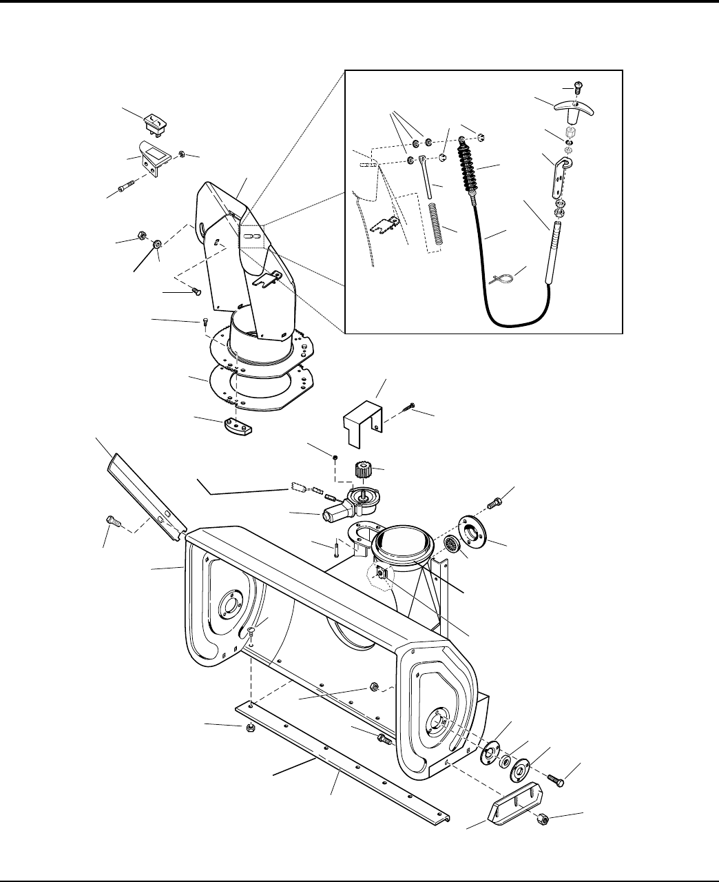
Auger Housing and Chute Group - 38" Models
NOTE: Unless noted otherwise,
use the standard hardware torque
specification chart.
Coat top and bottom of
chute ring with grease.
Scraper blade should
be on inside of housing.
When installing cable,
make sure it does not
come into contact with
muffler.
Plastic washer
(Ref. 3) place
between chute
and deflector.
See Handles and Controls
group for Wiring Harness.
Mount cable bracket (Ref. 20)
on right hand side of handle
using shift control bracket
hardware.
2
4
9
12
13
15
21
14
16
20
18 19
31
28
29
30
33 34
35
36
37
38
2
25
41
40
39
43
44
17
42
3
32
46
45
22
26
23
27
24
14
11
252510
6
7
8
5
1
987050
The above parts group applies to the following Mfg. Nos.:
2005 28
© Copyright Simplicity Manufacturing, Inc. All Rights Reserved.
1694872 - 1390E
1694915 - 1390EX
TP 400-4250-00-LW-S

PART NO. DESCRIPTIONREF NO QTY.
Auger Housing and Chute Group - 38" Models
Footnotes
1 1960001 3 SCREW, Hex Washer Head Pastite, 10-14 x 5/8
2 1931333 10 CARRIAGE BOLT, 5/16-18 x 3/4 G5
3 2860210 1 WASHER, Special, 97/250ID x 1-3/25OD x 3/100 Thick
4 1960686 1 NUT, Hex Falnge ESNA, 5/16-18
5 1923341 1 SCREW, Hex Whiz Lock, 1/4-20 x 3/4
6 1726992A 1 BRACKET, Mounting Switch
7 1724210 1 SWITCH, Rocker Chute
8 1933896 2 NUT, Hex Nylon 10-24
9 1731435C 1 CHUTE AND DEFLECTOR ASSEMBLY
10 1702219 3 SPACER, Heat Treated
11 1960126 2 NUT, Push Pal, 1/4" Diameter Stud Capped
12 1611945 1 ROD, 5/16" Diameter, Spring Guide
13 1611939 1 SPRING, Complete
14 1720446 1 CABLE AND KNOB ASSEMBLY, Chute (Includes Ref. No. 18, 19, 20, 21 & 22)
15 1611989 1 BOOT, Bellows
16 1719140 1 COLLET
17 1719139 1 SEAL, Rod
18 1719138 1 KNOB
19 1960600 1 SCREW, 8-32
20 1726411A 1 SUPPORT, Cable
21 2825094 1 TIE, Self Locking
22 1729645A 1 COVER, Pinion, 18GA
23 1925003 2 CAPSCREW, Hex Washer Head Taptite, 1/4-20 x 1/2
24 1728967 1 PINION, 1-3/20 LG
25 1960745 4 NUT, Hex KEPS, #10-24
26 1728965 1 MOTOR, Electric
27 2860604 3 SCREW, Hex Washer Head Slot, #10-24 x 1-1/4
28 1960738 9 CAPSCREW, Hex Head Whiz Lock, 5/16-18 x 3/4
29 1665982A 1 RETAINER, Bearing
30 1729578 1 BEARING, Ball
31 1930659 3 NUT, Retainer Speed, 5/16-18
32 2172279 2 FLANGE, Bearing, w/Fitting
33 2173934 2 BEARING, Cartridge
34 2172278 2 FLANGE, Bearing, 3/8" Deep
35 1925205 6 CAPSCREW, Hex head, 5/16-18 x 5/8
36 1960687 4 NUT, Hex Flange, 3/8-16 ESNA
37 1725747A 2 SKID SHOE, 7GA Formed, Heat Treated
38 1723921A 1 BLADE, Scraper, 35-3/4 for 38"
39 1960702 4 CARRIAGE BOLT, 3/8-16 x 1 G5
40 1931277 15 NUT, Hex Flange Whiz Lock, 5/16-18
41 1935048 9 NUT, Flange Lock, 5/16-18
42 1729734C 1 HOUSING AND IMPELLER ASSEMBLY, 38"
43 1664847 4 CAPSCREW, Hex Washer Head Taptite, 5/16-18 x 3/4 G5
44 1729642C 2 CUTTER, Drift, Red
The above parts group applies to the following Mfg. Nos.:
2005 29
© Copyright Simplicity Manufacturing, Inc. All Rights Reserved.
1694872 - 1390E
1694915 - 1390EX
TP 400-4250-00-LW-S
Auger Housing and Chute Group - 38" Models
NOTE: Unless noted otherwise,
use the standard hardware torque
specification chart.
Coat top and bottom of
chute ring with grease.
Scraper blade should
be on inside of housing.
When installing cable,
make sure it does not
come into contact with
muffler.
Plastic washer
(Ref. 3) place
between chute
and deflector.
See Handles and Controls
group for Wiring Harness.
Mount cable bracket (Ref. 20)
on right hand side of handle
using shift control bracket
hardware.
2
4
9
12
13
15
21
14
16
20
18 19
31
28
29
30
33 34
35
36
37
38
2
25
41
40
39
43
44
17
42
3
32
46
45
22
26
23
27
24
14
11
252510
6
7
8
5
1
987050
The above parts group applies to the following Mfg. Nos.:
2005 30
© Copyright Simplicity Manufacturing, Inc. All Rights Reserved.
1694872 - 1390E
1694915 - 1390EX
TP 400-4250-00-LW-S

PART NO. DESCRIPTIONREF NO QTY.
Auger Housing and Chute Group - 38" Models
Footnotes
45 1666613 3 HOLD DOWN, Chute
46 1717477A 1 GEAR, Chute
The above parts group applies to the following Mfg. Nos.:
2005 31
© Copyright Simplicity Manufacturing, Inc. All Rights Reserved.
1694872 - 1390E
1694915 - 1390EX
TP 400-4250-00-LW-S

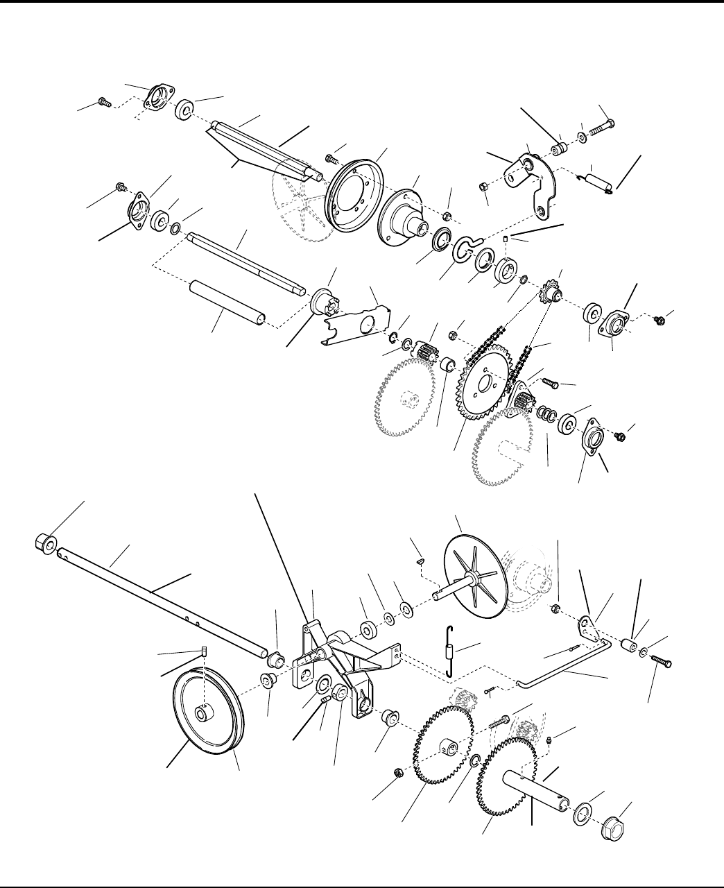
Traction Drive Group
NOTE: Unless noted otherwise,
use the standard hardware torque
specification chart.
Mounted inside of frame.
Mounted outside
of frame.
Grease I.D. teeth•
and flange.
Be sure tie bar support is in place. Move axle to
left (as viewed from back) to take up end play.
Move set collar (Ref. 49) to right to remove end
play in pivot arm (Ref. 40). Torque set screw
(Ref. 43) to 10 - 14 ft-lbs.
Apply grease to
bearing areas.
Mounted
outside of
frame.
Must pivot
freely.
Mount in
hole at
upper rear
corner of
frame.
Torque to•
18 - 21 ft-lbs.
Assemble Ref. 40, 44 & 51
with no end play. Parts
must rotate freely.
Grease bearing
area of Ref. 57.
Apply anti-seize
compound to wheel hub
area of Ref. 49 & 57.
Mount to bracket in
frame weldment.
Mounted outside
of frame.
Apply Loctite and•
Torque to 55 - 60
in-lbs. when all parts
are against hub.
Torque to
10 - 14 ft-lbs.
Pack groove
with grease.
Hook end to
top left corner
slot of frame.
Lubricate with
5W 50 Synthetic oil.
Apply loctite
(2 places).
1
2
3
4
56
7
9
10 11
12
13
14
15
16 17
18
1
20
21
22
23
24
25
26
27
28
29
31
32
48
49
46
44
51
50
45
26
42
41
52
53
1
20
2
3
3
2
19
60 1
47
46
33 26
57
56
38
39
40
55
58 59
50
33
39
34
36
35
37
54
15
8
30
8
2
3
43
987054
The above parts group applies to the following Mfg. Nos.:
2005 32
© Copyright Simplicity Manufacturing, Inc. All Rights Reserved.
1694847 - 10560E
1694848 - 10560EX
1694849 - 11570E
1694850 - E11570
1694851 - 1380E
1694852 - E1380
1694867 - 9560E
1694872 - 1390E
1694914 - 9560EX
1694915 - 1390EX
TP 400-4250-00-LW-S

PART NO. DESCRIPTIONREF NO QTY.
Traction Drive Group
Footnotes
1 1930601 8 SCREW, Hex Washer Head Taptite, 5/16-18 x 5/8
2 1667341 4 RETAINER, Bearing
3 1722703 4 BEARING, Ball
4 1726856 1 SHAFT, Hex
5 1921332 3 CAPSCREW, Hex Head, 5/16-18 x 3/4 G5
6 1725428 1 DISC, Friction with Insert
7 1665995 1 HUB, Friction Disc
8 1960684 6 NUT, Hex Keps, 5/16-18, Conical Washer
9 1960687 1 NUT, Hex Flange, 3/8-16 ESNA
10 1669256 1 ARM ASSEMBLY, Shift w/Bushing
11 1666114 1 BUSHING, 19/50 ID x 3/4 OD x 1-3/100 LG
12 1924940 1 WASHER, 3/8
13 1923701 1 CAPSCREW, Hex Head, 3/8-16 x 2 G5
14 1668255 1 SPRING, Extension
15 1678956 2 COLLAR, Thrust
16 1666207 1 PIN, Loop
17 1667335 1 COLLAR, Set
18 1724333 2 SCREW, Set Square Head Cup Point, 1/4-20 x 1/2
19 1726931 1 SPROCKET, 10 Tooth
20 2860164 4 WASHER, 5/8
21 1718752 1 JACKSHAFT, Double D
22 1720298 1 SPRING, Complete
23 1718689 1 CLUTCH, Sliding, 1/5LG, Powdered Metal
24 1720078A 1 ARM, Clutch
25 2827732 1 RING, Retaining Extension
26 1960114 3 WASHER, 3/4
27 1718688 1 GEAR, Stationary Clutch
28 1679556 1 SPACER, Heat Treated, 31/100 LG
29 1667330 1 SPROCKET
30 1666980 1 CHAIN, Roller
31 1718687 1 GEAR, Double D
32 1921333 3 CAPSCREW, Hex Head, 5/16-18 x 1 G5
33 1960686 2 NUT, Hex Flange, 5/16-18 ESNA
34 1700473 1 BELLCRANK
35 1666106 1 BUSHING, 11/32 ID x 3/4 OD x 1-3/50 LG
36 1919326 1 WASHER, 11/32 x 3/4 x 1/16
37 1922127 1 CAPSCREW, Hex Head, 5/16-18 x 1-3/4 G5
38 1726467 1 ROD, Pivot, 9-15/100 LG
39 1722460 1 PIN, Quick
40 1725666 1 SPRING, Extension
41 1719879 1 DRIVE DISC with SPINDLE
42 2818312 1 KEY, Woodruff, 47/250 x 5/8
43 1924366 1 WASHER, 5/8
44 1670849 1 ARM, Pivot with Bushings & Bearings (Includes Ref. Nos 45, 46, 47 & 48)
The above parts group applies to the following Mfg. Nos.:
2005 33
© Copyright Simplicity Manufacturing, Inc. All Rights Reserved.
1694847 - 10560E
1694848 - 10560EX
1694849 - 11570E
1694850 - E11570
1694851 - 1380E
1694852 - E1380
1694867 - 9560E
1694872 - 1390E
1694914 - 9560EX
1694915 - 1390EX
TP 400-4250-00-LW-S
Traction Drive Group
NOTE: Unless noted otherwise,
use the standard hardware torque
specification chart.
Mounted inside of frame.
Mounted outside
of frame.
Grease I.D. teeth•
and flange.
Be sure tie bar support is in place. Move axle to
left (as viewed from back) to take up end play.
Move set collar (Ref. 49) to right to remove end
play in pivot arm (Ref. 40). Torque set screw
(Ref. 43) to 10 - 14 ft-lbs.
Apply grease to
bearing areas.
Mounted
outside of
frame.
Must pivot
freely.
Mount in
hole at
upper rear
corner of
frame.
Torque to•
18 - 21 ft-lbs.
Assemble Ref. 40, 44 & 51
with no end play. Parts
must rotate freely.
Grease bearing
area of Ref. 57.
Apply anti-seize
compound to wheel hub
area of Ref. 49 & 57.
Mount to bracket in
frame weldment.
Mounted outside
of frame.
Apply Loctite and•
Torque to 55 - 60
in-lbs. when all parts
are against hub.
Torque to
10 - 14 ft-lbs.
Pack groove
with grease.
Hook end to
top left corner
slot of frame.
Lubricate with
5W 50 Synthetic oil.
Apply loctite
(2 places).
1
2
3
4
56
7
9
10 11
12
13
14
15
16 17
18
1
20
21
22
23
24
25
26
27
28
29
31
32
48
49
46
44
51
50
45
26
42
41
52
53
1
20
2
3
3
2
19
60 1
47
46
33 26
57
56
38
39
40
55
58 59
50
33
39
34
36
35
37
54
15
8
30
8
2
3
43
987054
The above parts group applies to the following Mfg. Nos.:
2005 34
© Copyright Simplicity Manufacturing, Inc. All Rights Reserved.
1694847 - 10560E
1694848 - 10560EX
1694849 - 11570E
1694850 - E11570
1694851 - 1380E
1694852 - E1380
1694867 - 9560E
1694872 - 1390E
1694914 - 9560EX
1694915 - 1390EX
TP 400-4250-00-LW-S

PART NO. DESCRIPTIONREF NO QTY.
Traction Drive Group
Footnotes
45 1665521 1 BEARING, Ball
46 1666425 2 BUSHING, 3/4 ID x 1 OD x 3/4 LG, Powder Metal
47 1666855 1 BUSHING, 5/8 ID x 13/16 OD x 3/4 LG, Powder Metal
48 1666001 1 BUSHING, 377/100 ID x 1-13/100 OD x 1 LG, Powdered Metal
49 1720299 1 AXLE, Round
50 1928721 2 SCREW, Set Square Head Cup Point, 5/16-18 x 1/2 G8
51 1672595A 1 PULLEY AND HUB ASSEMBLY
52 1919394 1 WASHER, 1
53 1729254 1 COLLAR, Set
54 1720300 1 GEAR AND HUB ASSEMBLY, RH
55 1930570 1 CAPSCREW, Hex Head, 5/16-18 x 1-1/2 G8
56 2812808 1 FITTING, Lube 1/4-28, Tappered with Check Ball
57 1730228 1 GEAR AND HUB ASSEMBLY, with Bushings
58 2860169 1 WASHER, 1-47/250
59 1720305 1 BUSHING, 1-27/200 ID x 1-157/250 OD x 3/4 LG
60 2172206 1 RING, Retaining External #87
The above parts group applies to the following Mfg. Nos.:
2005 35
© Copyright Simplicity Manufacturing, Inc. All Rights Reserved.
1694847 - 10560E
1694848 - 10560EX
1694849 - 11570E
1694850 - E11570
1694851 - 1380E
1694852 - E1380
1694867 - 9560E
1694872 - 1390E
1694914 - 9560EX
1694915 - 1390EX
TP 400-4250-00-LW-S
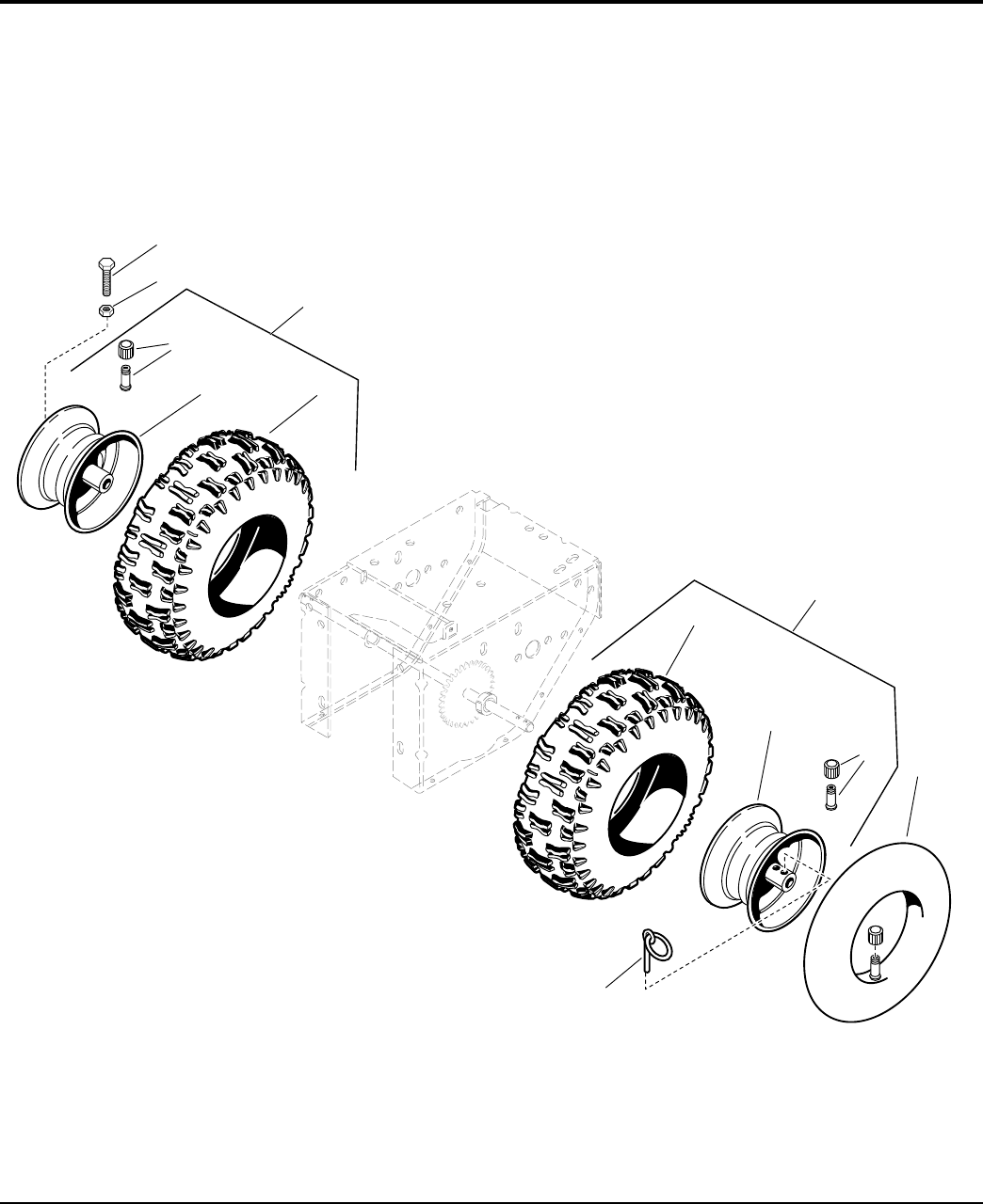
Wheels & Tires Group
NOTE: Unless noted otherwise,
use the standard hardware torque
specification chart.
8
9
10
6
6
4
5
4
1
2
3
7
986549
The above parts group applies to the following Mfg. Nos.:
2005 36
© Copyright Simplicity Manufacturing, Inc. All Rights Reserved.
1694847 - 10560E
1694848 - 10560EX
1694849 - 11570E
1694850 - E11570
1694851 - 1380E
1694852 - E1380
1694867 - 9560E
1694872 - 1390E
1694914 - 9560EX
1694915 - 1390EX
TP 400-4250-00-LW-S

PART NO. DESCRIPTIONREF NO QTY.
Wheels & Tires Group
Footnotes
1 1921978 1 CAPSCREW, Hex Head 5/16-18 x 2 G5
2 1919438 1 NUT, Hex Lock ESNA Light 5/16-18 NC-3B
3 1726743 1 WHEEL & TIRE ASSEMBLY, Snow R.H. (Used on 24 & 28 in. Models)
3 1726745 1 WHEEL & TIRE ASSEMBLY, Snow R.H. (Used on 32 & 38 in. Models)
4 2172353 2 VALVE STEM & CAP ASSEMBLY, Air
5 1714242 1 HUB, Wheel R.H., 3-3/4 Wide 8 Diameter 3/4 ID (Used on 24 & 28 in. Models)
5 1722762 1 HUB, Wheel, 5-3/8 Wide 8 Diameter 3/4 ID (Used on 32 & 38 in. Models)
6 1727074 2 TIRE, 4.80/4.00-8, X-TRAC TL (Used on 24 & 28 in. Models)
6 1727075 2 TIRE, 16 x 6.5-8 X-TRAC TL (Used on 32 & 38 in. Models)
7 1726742 1 WHEEL & TIRE ASSEMBLY, Snow L.H. (Used on 24 & 28 in. Models)
7 1726744 1 WHEEL & TIRE ASSEMBLY, Snow L.H. (Used on 32 & 38 in. Models)
8 1720307 1 HUB, Wheel L.H., 3-3/4 Wide 8 Diameter 1-1/8 ID (Used on 24 & 28 in. Models)
8 1722761 1 HUB, Wheel 5-3/8 Wide 8 Diameter 1-1/8 ID (Used on 32 & 38 in. Models)
9 2153038 2 TUBE, Tire
10 1666969 1 PIN, KLIK, Ring
The above parts group applies to the following Mfg. Nos.:
2005 37
© Copyright Simplicity Manufacturing, Inc. All Rights Reserved.
1694847 - 10560E
1694848 - 10560EX
1694849 - 11570E
1694850 - E11570
1694851 - 1380E
1694852 - E1380
1694867 - 9560E
1694872 - 1390E
1694914 - 9560EX
1694915 - 1390EX
TP 400-4250-00-LW-S
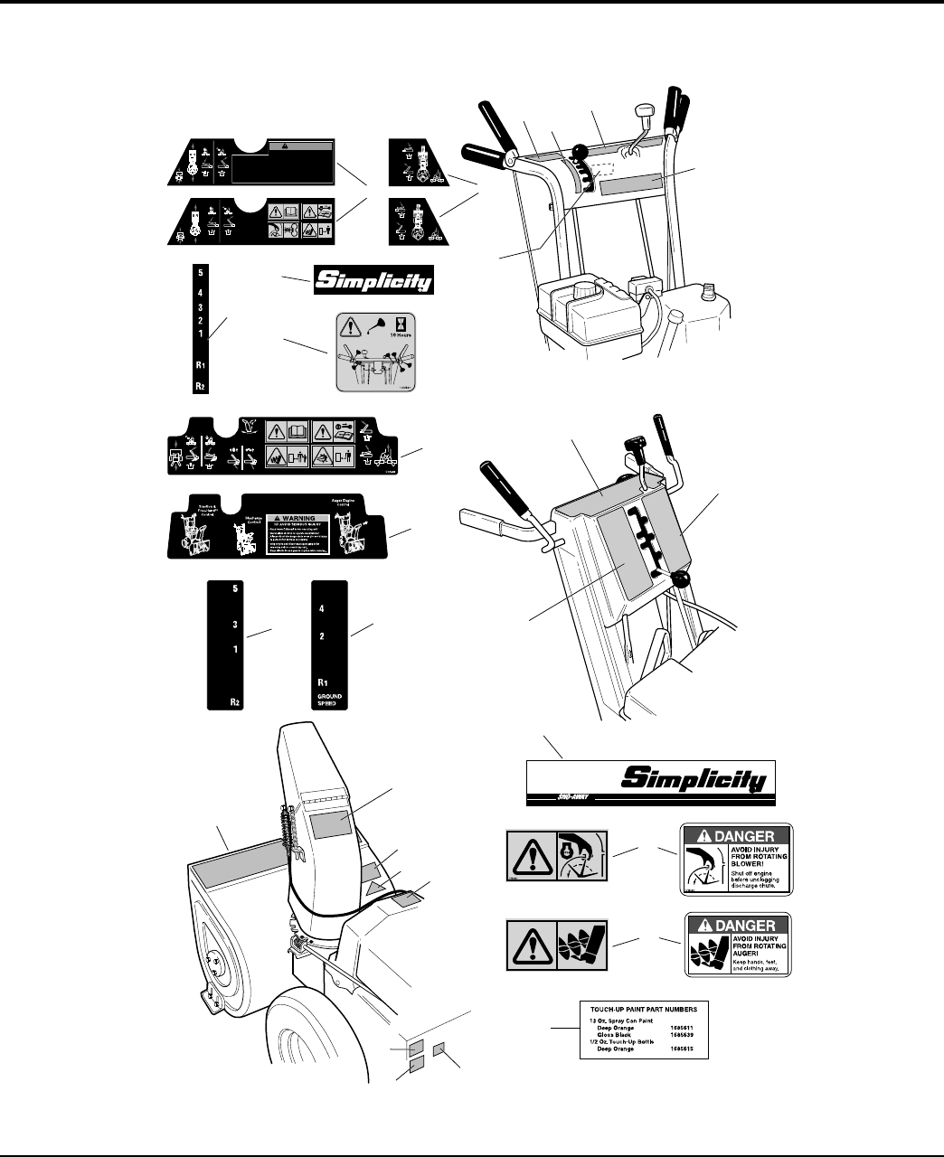
Decal Group
NOTE: Unless noted otherwise,
use the standard hardware torque
specification chart.
171653 2
1726946
Au ger
Disengage
Au ger
Enga ge
1727023
Traction
Dise ngage
Traction
Engage
Free H and
Unlocked
Free H and
Locked
AVOID SERIOUS INJURY OR DEATH
• Read the o perat or's manu al fo r op eratin g an d safet y
instructions.
• Do not defea t the safety f eatures of co ntro l. They ar e
for your protection.
• Keep machi ne p roperl y mai ntai ned and service d wit h
all shi eld s, g uards, and prot ectiv e devi ces in pl ace.
• Never all ow ch il dren t o op erate sn owth rowe r.
• Keep area of operat ion clear of al l p ersons ,
especially children.
• Al ways di rect d isch arge ch ute so as to avoi d
injury to persons or damage to property.
• Stop engine and disconnect spark plug wire
before servicing the unit.
• When traction and auger control s are depressed,
th e Free Ha nd™ con trol is act ivat ed. T hi s all ows
th e auge r cont rol t o b e released , yet auge r
rotation will continue until the Free Hand control
is released.
WA R NI N G
1727020
1727021
8
6
7
9
10
11
13
15
15
16
8
6
7
10
11
6
9
2
4
3
2
1
4
5
5
13
14
12
987131
The above parts group applies to the following Mfg. Nos.:
2005 38
© Copyright Simplicity Manufacturing, Inc. All Rights Reserved.
1694847 - 10560E
1694848 - 10560EX
1694849 - 11570E
1694850 - E11570
1694851 - 1380E
1694852 - E1380
1694867 - 9560E
1694872 - 1390E
1694914 - 9560EX
1694915 - 1390EX
TP 400-4250-00-LW-S

PART NO. DESCRIPTIONREF NO QTY.
Decal Group
Footnotes
1 1726945 1 DECAL, Dashboard EZ Turn L.H. (Tube Handle Models Only)
1 1727022 1 DECAL, Dashboard EZ Turn L.H. (CE)
2 1715557 1 DECAL, 5 4 3 2 1 R1 R2, Shift Pattern (Tube Handle Models Only)
3 1726946 1 DECAL, Auger Control R.H. (Tube Handle Models Only)
3 1727023 1 DECAL, Auger Control R.H. (CE)
4 1715558 1 DECAL, Simplicity (Tube Handle Models Only)
5 1722867 1 DECAL, Handle Lubrication (Tube Handle Models Only)
6 1726947 1 DECAL, Dashboard EZ Turn (Channel Handles)
6 1727024 1 DECAL, Dashboard EZ Turn (Channel Handles) (CE)
7 1714245 1 DECAL, 4 2 R1 Ground Speed, R.H. (Channel Handle Models Only)
8 1714246 1 DECAL, 5 3 1 R2, Shift Pattern, L.H. (Channel Handle Models Only)
9 1727019 1 DECAL, Stripe, 9560
9 1731195 1 DECAL, Stripe, 10560
9 1731196 1 DECAL, Stripe, 11570
9 1731197 1 DECAL, Stripe, 1380
9 1724075 1 DECAL, Stripe, 1390
10 7071880 1 DECAL, DANGER Chute Cleaning
10 1727207 1 DECAL, WARNING Chute Cleaning (CE)
11 1716532 1 DECAL, DANGER Avoid Injury from Auger
11 1727208 1 DECAL, WARNING Impeller (CE)
12 * 1 DECAL, OPEI Certified
13 1725507 1 DECAL, Power Boost (Channel Handle Models Only)
14 * 1 DECAL, Patent
14 * 2 LABEL, Decibel, Power MASS (CE)
15 1720454 1 DECAL, Touch Up Paint, Orange
16 * 1 DECAL, Serial I.D. Tag
* Not a serviceable part.
The above parts group applies to the following Mfg. Nos.:
2005 39
© Copyright Simplicity Manufacturing, Inc. All Rights Reserved.
1694847 - 10560E
1694848 - 10560EX
1694849 - 11570E
1694850 - E11570
1694851 - 1380E
1694852 - E1380
1694867 - 9560E
1694872 - 1390E
1694914 - 9560EX
1694915 - 1390EX
TP 400-4250-00-LW-S

Headlight Group
NOTE: Unless noted otherwise,
use the standard hardware torque
specification chart.
Existing
Hardware
1
2
5
4
6
7
3
986371
The above parts group applies to the following Mfg. Nos.:
2005 40
© Copyright Simplicity Manufacturing, Inc. All Rights Reserved.
1694847 - 10560E
1694848 - 10560EX
1694849 - 11570E
1694850 - E11570
1694851 - 1380E
1694852 - E1380
1694872 - 1390E
1694915 - 1390EX
TP 400-4250-00-LW-S

PART NO. DESCRIPTIONREF NO QTY.
Headlight Group
Footnotes
1 1725291 1 HEADLIGHT ASEMBLY
2 1701011 2 TIE, Self Locking
3 2834683 1 CLIP, Wire
4 1709256A 1 LOCKWSHER, 5/16
5 1917372 1 NUT, Hex, 5/16-18
6 1725292C 1 BRACKET
7 1931333 1 CARRIAGE BOLT, 5/16-18 x 3/4
The above parts group applies to the following Mfg. Nos.:
2005 41
© Copyright Simplicity Manufacturing, Inc. All Rights Reserved.
1694847 - 10560E
1694848 - 10560EX
1694849 - 11570E
1694850 - E11570
1694851 - 1380E
1694852 - E1380
1694872 - 1390E
1694915 - 1390EX
TP 400-4250-00-LW-S
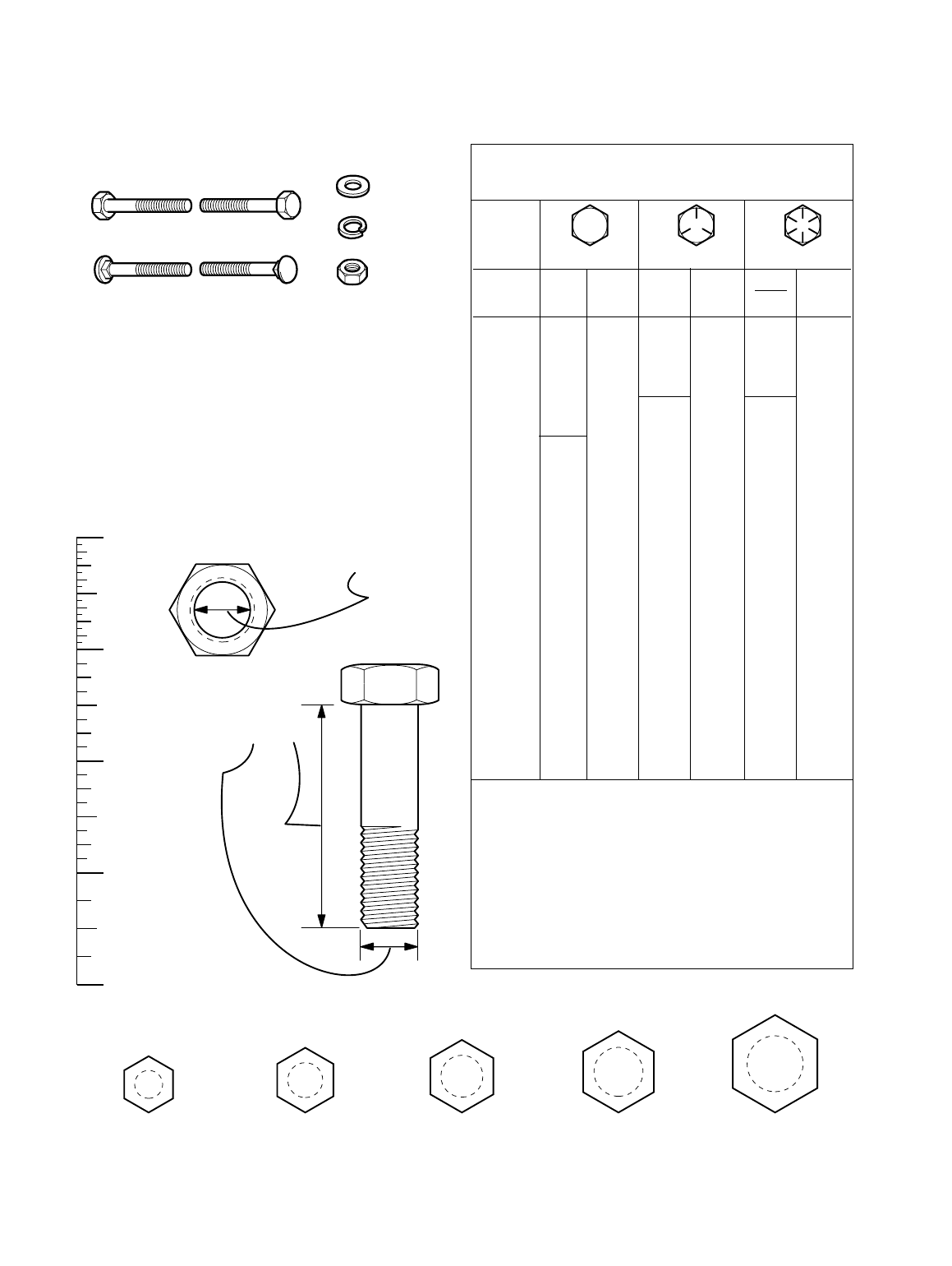
Torque Specification Chart
FOR STANDARD MACHINE HARDWARE (Tolerance ± 20%)
Hardware
Grade
SAE Grade 2 SAE Grade 5 SAE Grade 8
Size Of
in/lbs in/lbs
in/lbs
Hardware ft/lbs Nm. ft/lbs Nm. ft/lbs Nm.
8-32
19
2.1
30
3.4
41
4.6
8-36
20
2.3
31
3.5
43
4.9
10-24
27
3.1
43
4.9
60
6.8
10-32
31
3.5
49
5.5
68
7.7
1/4-20
66
7.6 810.9 12 16.3
1/4-28
76
8.6 10 13.6 14 19.0
5/16-18 11 15.0 17 23.1 25 34.0
5/16-24 12 16.3 19 25.8 27 34.0
3/8-16 20 27.2 30 40.8 45 61.2
3/8-24 23 31.3 35 47.6 50 68.0
7/16-14 30 40.8 50 68.0 70 95.2
7/16-20 35 47.6 55 74.8 80 108.8
1/2-13 50 68.0 75 102.0 110 149.6
1/2-20 55 74.8 90 122.4 120 163.2
9/16-12 65 88.4 110 149.6 150 204.0
9/16-18 75 102.0 120 163.2 170 231.2
5/8-11 90 122.4 150 204.0 220 299.2
5/8-18 100 136 180 244.8 240 326.4
3/4-10 160 217.6 260 353.6 386 525.0
3/4-16 180 244.8 300 408.0 420 571.2
7/8-9 140 190.4 400 544.0 600 816.0
7/8-14 155 210.8 440 598.4 660 897.6
1-8 220 299.2 580 788.8 900 1,244.0
1-12 240 326.4 640 870.4 1,000 1,360.0
Hex Head Capscrew
Hex Nut
Lockwasher
Washer
Carriage Bolt
NOTES
1. These torque values are to be used for all hardware
excluding: locknuts, self-tapping screws, thread forming
screws, sheet metal screws and socket head setscrews.
2. Recommended seating torque values for locknuts:
a. for prevailing torque locknuts - use 65% of grade 5
torques.
b. for flange whizlock nuts and screws - use 135% of
grade 5 torques.
3. Unless otherwise noted on assembly drawings, all torque
values must meet this specification.
Hardware Identification & Torque Specifications
Common Hardware Types
Screw, 1/2 x 2
Body
Diameter
Body
Length
Inside
Diameter
Nut, 1/2”
No
Marks
3/8” Bolt or Nut
Wrench—9/16”
3/8
5/16” Bolt or Nut
Wrench—1/2”
5/16
1/4” Bolt or Nut
Wrench—7/16”
1/4
1/2” Bolt or Nut
Wrench—3/4”
1/2
DIA.
7/16
DIA.
7/16” Bolt or Nut
Wrench (Bolt)—5/8”
Wrench (Nut)—11/16”
Wrench & Fastener Size Guide
Standard Hardware Sizing
When a washer or nut is identified as 1/2”, this is the
Nominal size
, meaning the
inside diameter
is 1/2 inch; if a
second number is present it represent the
threads per inch
When bolt or capscrew is identified as 1/2 - 16 x 2”, this
means the
Nominal size
, or
body diameter
is 1/2 inch; the
second number represents the
threads per inch
(16 in this
example, and the final number is the
body length
of the
bolt or screw (in this example 2 inches long).
The guides and ruler furnished below are designed to
help you select the appropriate hardware and tools.
0
1/4 3/4
1/2
1
1/4 3/4
1/2
2
1/4 3/4
1/2
3
1/4 3/4
1/2
4

500 N. Spring Street / PO Box 997
Port Washington, WI 53074-0997 USA
www.simplicitymfg.com
MANUFACTURING, INC.
© Copyright Simplicity Manufacturing, Inc.
All Rights Reserved. Printed In USA.
2005
