Single Chip Systems S512-C InstaScan Scanner, Model 512-C User Manual 512 C Manual
Single Chip Systems Corporation InstaScan Scanner, Model 512-C 512 C Manual
UserManual.wiki
>
Single Chip Systems
>
S512 C User Manual
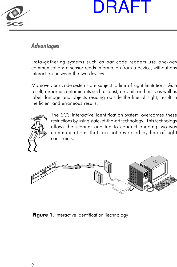
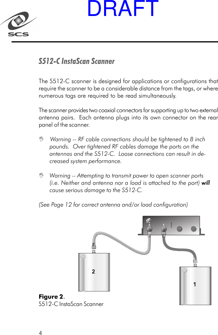
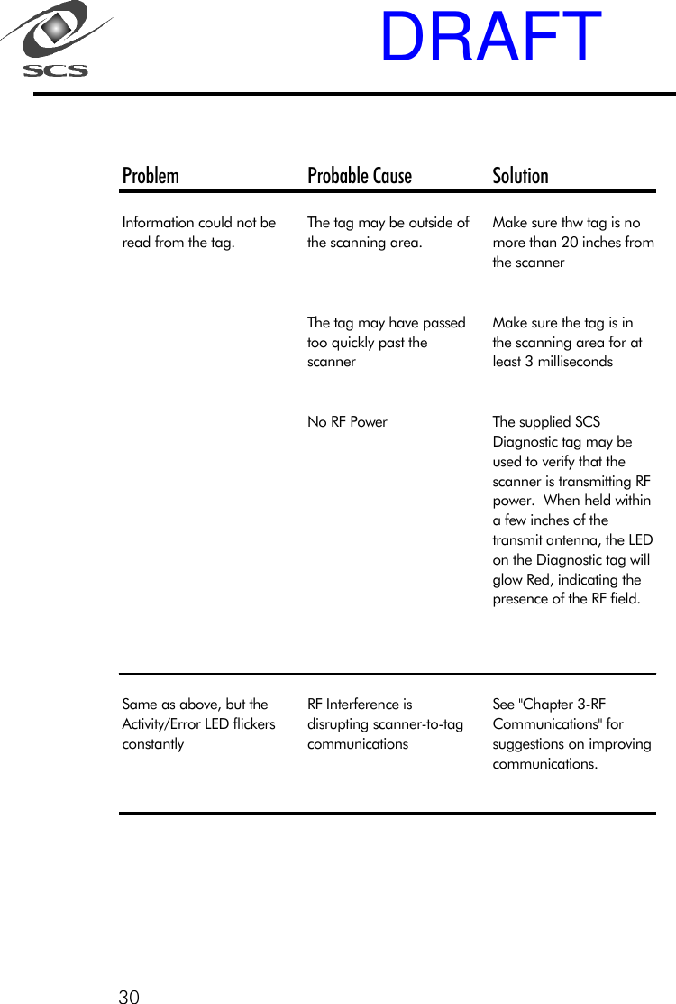
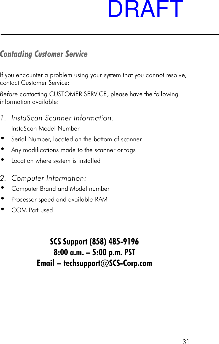
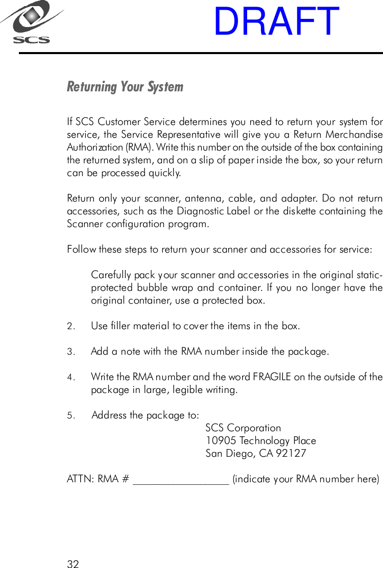
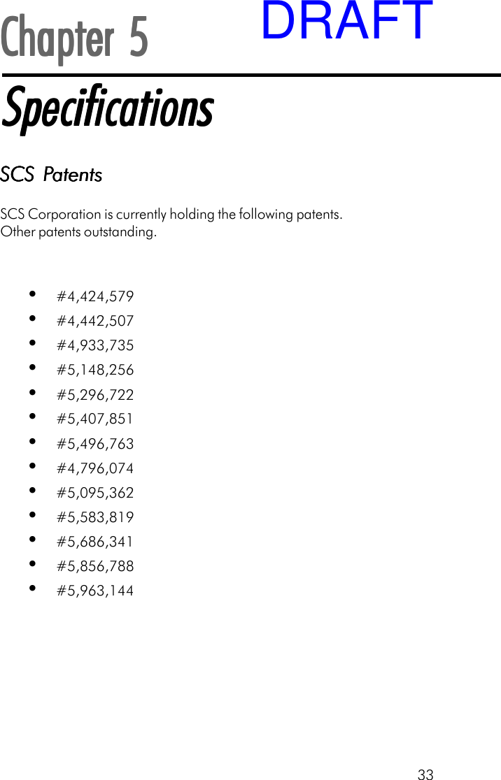
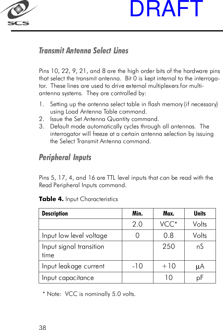
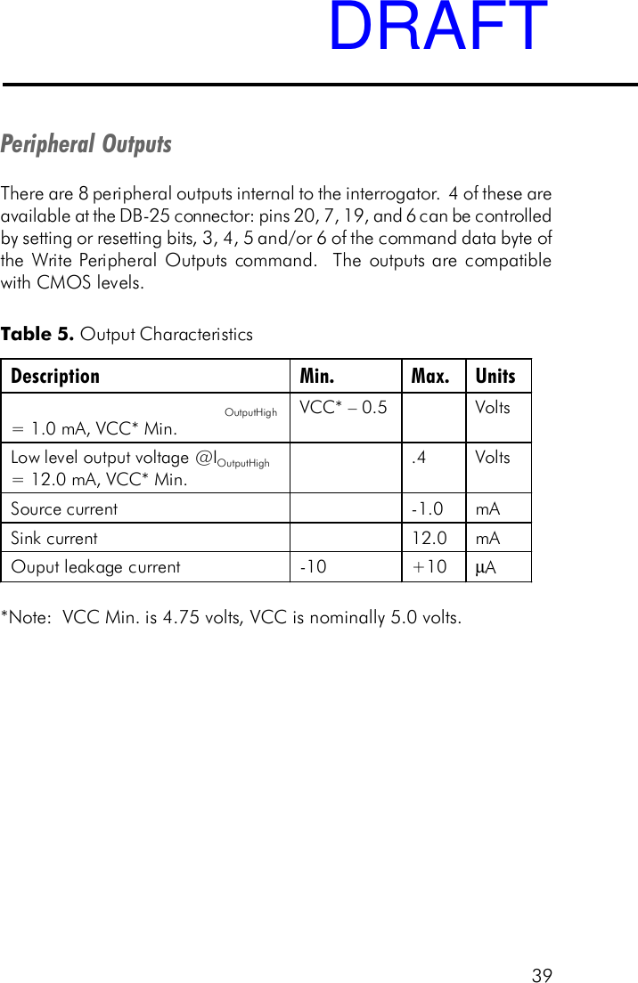
draft users manual
Navigation menu
Upload a User Manual
Namespaces
Wiki Guide
HTML
PDF
Info
Views
User Manual
Discussion / Help
Navigation