Single Chip Systems S512-C InstaScan Scanner, Model 512-C User Manual 512 C Manual
Single Chip Systems Corporation InstaScan Scanner, Model 512-C 512 C Manual
draft users manual

INSTASCAN© SCANNER
MODEL S512-C
Operations Manual
SCS Corporation
10905 Technology Place, San Diego, CA 92127
Phone: 858-485-9196 • Fax: 858-485-0561
www.scs-corp.com • info@scs-corp.com
DRAFT

licensed products of SCS. This Operations Manual contains proprietary
information protected by copyright and this Operations Manual and all
accompanying hardware, software, and documentation are copyrighted.
SCS does not warrant that the hardware will work properly in all environments
and applications, and makes no warranty and representation, either implied
or expressed, with respect to the quality, performance, or fitness for a particular
purpose.
Information in this Operations Manual is subject to change without notice
and does not represent a commitment on the part of SCS. SCS assumes
no responsibility for incidental damage that may result do to any
inaccuracies that may be contained in this Operations Manual.
SCS makes no commitment to update or keep current the information in
this Operations Manual, and reserves the right to make changes to this
Operations Manual and/or product without notice.
No part of this manual may be reproduced or transmitted in any form or
by any means, electronic or mechanical, including photocopying, recording,
or information storage and retrieval systems, for any purpose other than
the purchaser’s personal use, without the express written permission of
SCS.
MS-DOS and Windows are registered trademarks of Microsoft Corporation.
All other trademarks or registered trademarks listed belong to their respective owners.
InstaScan and Dura-label are trademarks of SCS Corporation.
Version 100837-1 Rev. A
©Copyright 2002 SCS 10905 Technology Place San Diego, C A 92127
ii
DRAFT

iii
Contents
Chapter 1— Introduction ....................................................... 1
Advantages ..................................................................... 2
S512-C InstaScan Scanner ................................................ 4
What Else You Need ......................................................... 5
Summary of Chapters ........................................................ 6
Chapter 2 — Installation ....................................................... 7
LEDs and Connectors ...................................................... 7
Front Panel..................................................................... 8
Rear Panel.................................................................... 10
Scanner Installation Steps .............................................. 11
Connecting External Antennas........................................ 12
Placing the Antennas..................................................... 13
Connecting to a PC Serial Port or RS-232 ....................... 14
Connecting to an AC Outlet............................................ 15
Testing the Scanner Setup ................................................ 16
Aligning the Antenna ...................................................... 19
Installing Dura-labels ...................................................... 20
Reading Information from your Dura-labels ....................... 21
Writing information to your Dura-label.............................. 22
Loading Your Application ................................................ 23
Chapter 3 — RF Communications ........................................ 24
Signal Interference ........................................................ 25
Signal Attenuation/Reflections........................................ 26
Optimizing Performance ................................................ 27
DRAFT

iv
Chapter 4 — Troubleshooting .............................................. 28
Solving Problems........................................................... 28
Contacting Customer Service ......................................... 31
Returning Your System .................................................... 31
Chapter 5 — Specifications ................................................. 33
SCS Patents ................................................................... 33
S512-C Scanner Specifications......................................... 34
Chapter 6 — DB-25 Connector Function............................... 36
Pin Assignments ............................................................ 37
Receive Antenna Select Lines.......................................... 37
Transmit Antenna Select Lines......................................... 38
Peripheral Inputs ........................................................... 38
Peripheral Outputs ........................................................ 39
Limited Warranty ........................................................... 41
FCC Part 15 Compliance ................................................ 41
Radio Frequency exposure limits ....................................... 42
Disclaimer..................................................................... 42
DRAFT

1
Chapter 1Chapter 1
Chapter 1Chapter 1
Chapter 1
IntroductionIntroduction
IntroductionIntroduction
Introduction
The S512-C InstaScan scanner and the Dura-label radio frequency
(RF) tags developed by SCS are state-of-the-art data gathering
and inspection systems that combine sophisticated Interactive
Identification technology in a compact form factor. This unique synergy
allows our system to integrate seamlessly into — and significantly increase
productivity for — a wide range of applications and environments.
This system consists of the following components:
A scanner that writes information to and reads information from RF tags
using a read/write head (antenna). The scanner conforms to FCC Part
15 specifications and can operate with one or two externally connected
antennas.
Dura-label RF tags that contain information programmed by the
scanner. These tags are designed to store information under
extremely harsh environments without requiring a battery, and
the read/write tags can store a permanent record of multiple
events and transactions.
Communications between the scanner and the tags are conducted using
a revolutionary two-way technology that provides superior advantages
over conventional communication methods. The specific data being
communicated, and the amount of interaction you have with the scanner
and the tag are determined by your application.
DRAFT
2
Advantages
Data-gathering systems such as bar code readers use one-way
communication: a sensor reads information from a device, without any
interaction between the two devices.
Moreover, bar code systems are subject to line-of-sight limitations. As a
result, airborne contaminants such as dust, dirt, oil, and mist, as well as
label damage and objects residing outside the line of sight, result in
inefficient and erroneous results.
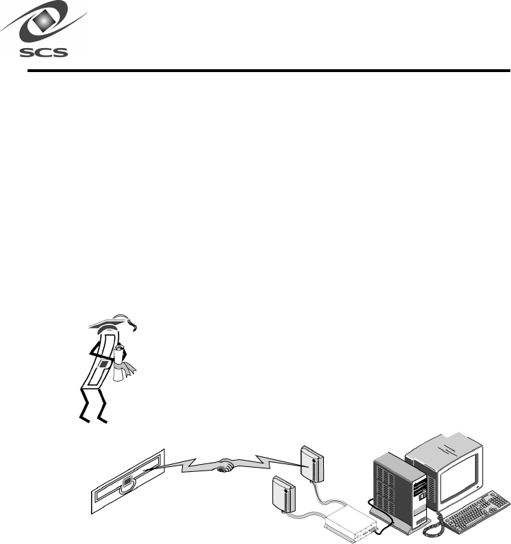
The SCS Interactive Identification System overcomes these
restrictions by using state-of-the-art technology. This technology
allows the scanner and tag to conduct ongoing two-way
communications that are not restricted by line-of-sight
constraints.
Figure 1. Interactive Identification Technology
DRAFT

3
This unique capability allows:
• Collective or selective data to be read from a single tag.
• Collective or selective data to be read from multiple tags without
requiring sorting or unpacking.
• Classes of tags to be filtered according to user-defined criteria.
This technology employs a superior interrogation feature that enables
applications to uniquely identify all tags in the scan field, without
misidentification or identifying the same tag multiple times.
Its technology also uses a robust protocol that maintains a uniform per
tag scan time, regardless of the number of tags in the scan field. The
protocol provides a flexible software application interface that can be
customized to the specific needs of particular industries and markets.
These unparalleled capabilities make our system an ideal solution for
logistics and warehousing, automatic sortation, pallet tracking, and anti-
diversion/anti-counterfeiting applications.
DRAFT
4
S512-C InstaScan Scanner
The S512-C scanner is designed for applications or configurations that
require the scanner to be a considerable distance from the tags, or where
numerous tags are required to be read simultaneously.
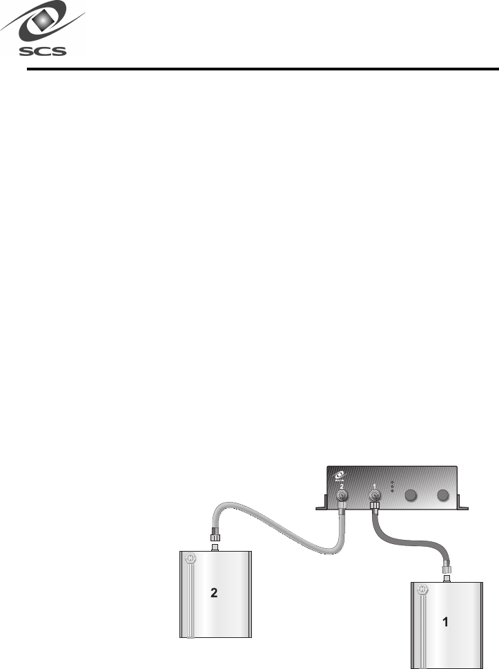
The scanner provides two coaxial connectors for supporting up to two external
antenna pairs. Each antenna plugs into its own connector on the rear
panel of the scanner.
Warning -- RF cable connections should be tightened to 8 inch
pounds. Over tightened RF cables damage the ports on the
antennas and the S512-C. Loose connections can result in de-
creased system performance.
Warning -- Attempting to transmit power to open scanner ports
(i.e. Neither and antenna nor a load is attached to the port) willwill
willwill
will
cause serious damage to the S512-C.
(See Page 12 for correct antenna and/or load configuration)
Figure 2.
S512-C InstaScan Scanner
DRAFT

5
What Else You Need
To complete your system, you need an IBM or compatible personal
computer with the following minimum system requirements:
• 486 processor or better
• Compatible screen and keyboard
• 9-pin RS-232 port
• Windows 95 or 98
• 16 MB of RAM (32+ MB recommended)
The applications you use to interface with this system may have additional
hardware and software requirements. For more information, consult the
manual that came with your applications.
DRAFT

6
Summary of Chapters
Besides Chapter 1, this Operations Manual contains the following
additional chapters:
• Chapter 2, Installation – describes how to install the scanner
and tag(s)
• Chapter 3, RF Communication - provides information on radio
frequency (RF) communications
• Chapter 4, Troubleshooting – describes how to identify, resolve,
and avoid problems when using the scanner and tag. This
chapter also contains Customer Service information and
merchandise return instructions
• Chapter 5, Specifications – lists scanner specifications
• Chapter 6, DB-25 Connector Function — describes the 25-pin
connector of the S512-C scanner.
DRAFT
7
Chapter 2Chapter 2
Chapter 2Chapter 2
Chapter 2
InstallationInstallation
InstallationInstallation
Installation
This chapter provides instructions for installing the S512-C
scanner and tag(s).
LEDs and Connectors
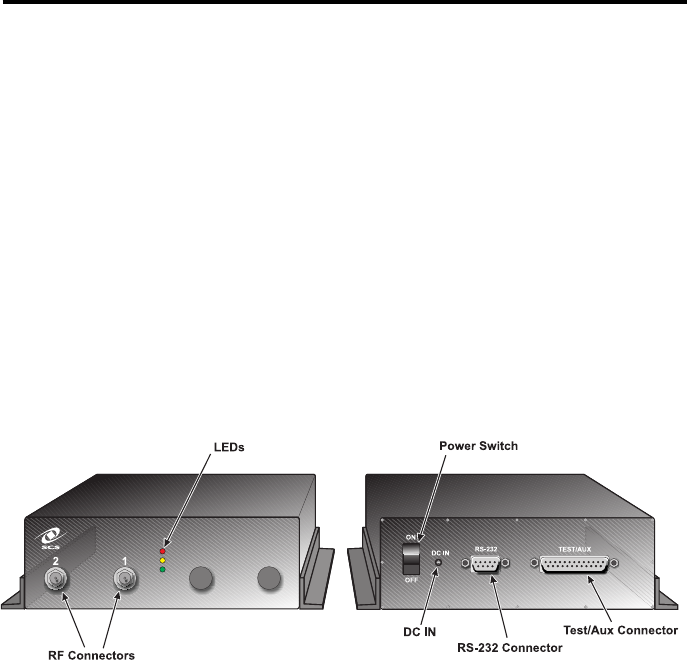
The scanner provides the connectors and LEDs described in the following
sections and shown in Figure 3.
Figure 3. LEDs and Connectors
DRAFT
8
Front Panel
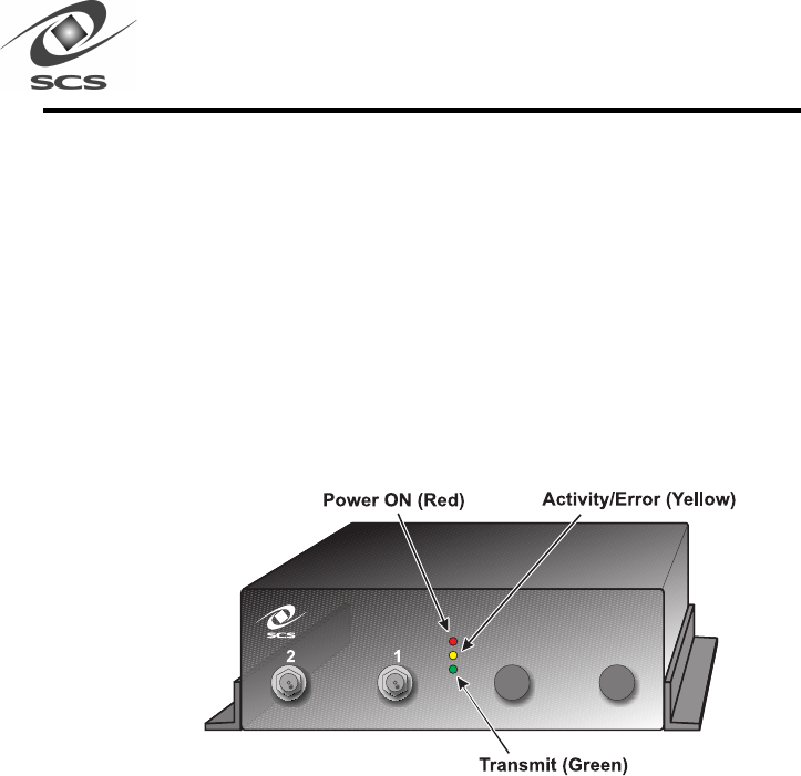
The scanner front panel has three LEDs (as shown in Figure 4) indicating
power, activity, and transmitter On/Off status (see Table 1 which describes
the meanings of the LEDs). The front panel has two coaxial connectors for
connecting external antennas. Either one or two antennas can be connected
to the scanner. For instructions on connecting antennas to the scanner,
refer to page 12.
Figure 4. S512-C InstaScan Scanner
Warning -- Attempting to transmit power to open scanner ports
(i.e. Neither and antenna nor a load is attached to the port) willwill
willwill
will
cause serious damage to the S512-C.
DRAFT

9
Table 1. .
. .
. S512-C Scanner LED Meanings
LED Color Status
Power ON Red ON = scanner is turned on
and receiving power from
external power supply
Activity/Error Yellow Flicker = scanner detects tag
information
Constant flickering with no tag
in the scanning field =
(a) Noisy environment or
possible interference, resulting in
diminished tag reading.
(b) Loose cable or bad connector
Transit On Green On = Scanner is transmitting
RF signals
DRAFT

10
Rear Panel
The scanner rear panel has an On/Off switch.
In the ON (up) position, the scanner is turned on. The red Power
ON LED should go ON, indicating that the scanner is receiving
power.
In the OFF (down) position, the scanner is turned off and not
receiving power, even if connected to a power outlet.
The rear panel also contains three connectors. The small round connector
is a standard DC power receptacle. The power supply provided with the
scanner should be plugged into this connector and into the wall outlet.
For more information, refer to “Connecting to an AC Outlet”
on page 15.
The small multi-pin connector is the 9-pin RS-232 port. The RS-232 serial
port connector allows the scanner to communicate with a personal computer
through the PC’s serial port. For more information on making this
connection, refer to page 14.
The large multi-pin connector is the 25 pin test connector. This connector
should only be used by a qualified system integrator.
DRAFT

11
Scanner Installation Steps
The scanner installation consists of the following steps:
1. Position the scanner — locate near desired antenna locations.
2. Connect external antennas — see page 12.
3. Place the antenna for optimum read/write operation —
see page 13.
4. Connect the scanner to PC serial port or RS-232— see page 14.
5. Connecting to an AC outlet — see page 15.
6. Testing the Scanner Setup — see page 16.
7. Aligning the antenna — see page 19.
DRAFT
12
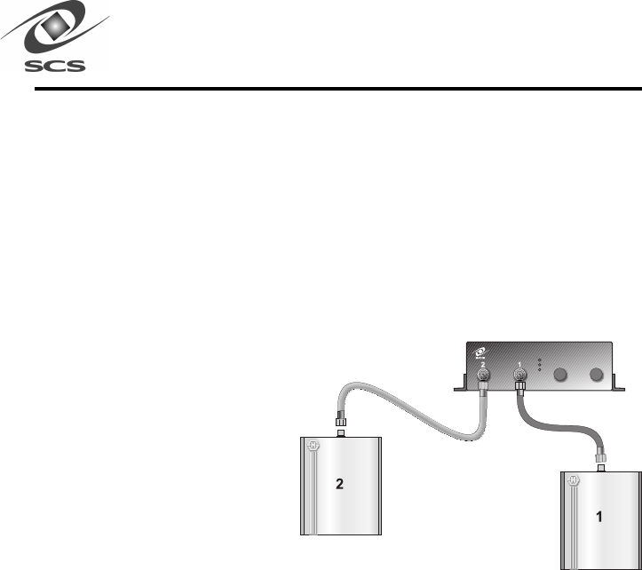
Connecting External Antennas
The front panel has two coaxial antenna connectors. Each connector
accommodates a single external antenna. Figure 5 shows the external
antenna connections to the scanner. The S512-C scanner uses one or two
antennas. When looking at the front panel, from left to right, the antenna
ports are numbered “2” and “1” (see Figure 5). If using one antenna, it
should be connected to antenna port “1”, and antenna port “2” should be
terminated with a 50 ohm load.
Figure 5. Connecting
External Antennas
Warning -- RF
cable connections
should be
tightened to 8
inch pounds.
Over tightened RF cables damage the ports on the antennas and
the S512-C. Loose connections can result in decreased system
performance.
Warning -- Attempting to transmit power to open scanner ports
(i.e. Neither and antenna nor a load is attached to the port) willwill
willwill
will
cause serious damage to the S512-C.
DRAFT

13
Placing the Antenna
Antenna placement is critical to ensuring that information is written to
and read from tags accurately. Observe the following guidelines when
placing the antenna:
Locate the antennas away from metal objects, microwave ovens, and
other devices that may induce radio frequency interference. In addi-
tion, make sure there are no metallic surfaces between, or in relative
proximity to, the scanner and tag. For additional placement consider-
ations, refer to “RF Communications” on page 24.
When reading, the scanner’s antenna(s) should be placed no more
than 20 inches from the objects bearing tags. When writing, the
scanner’s antenna should be no more than 4 inches from objects
bearing tags.
Tags must reside within the scan field for at least 3 milliseconds for
information to be retrieved from them.
DRAFT

14
Connecting to a PC Serial Port or RS-232
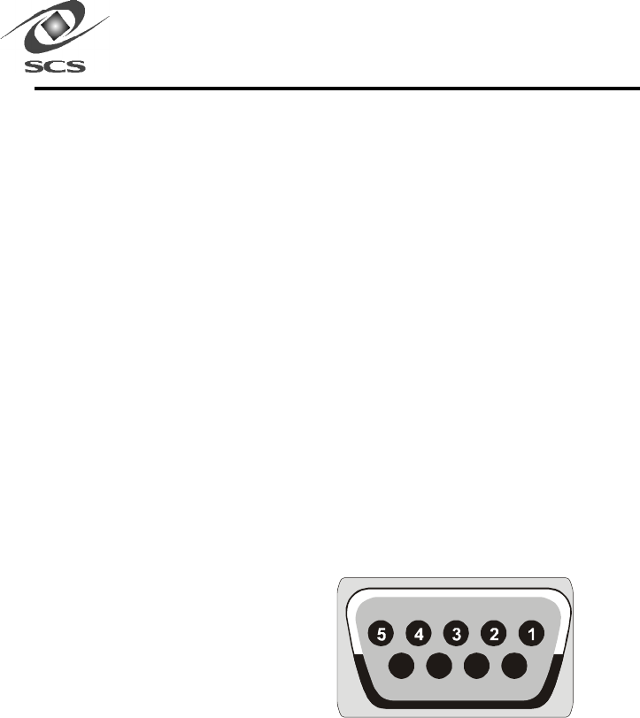
The scanner has a 9-pin female RS-232 connector that connects to a
serial port or RS-232 connector on an IBM or compatible personal
computer. The serial port can operate up to 57,600 bps.
To make this connection, you need:
An appropriately configured serial cable.
One of the following adapters, if your computer’s serial port does
not have a 9-pin connector:
- A 15-pin to 9-pin adapter, if your computer has a 15-pin serial
port connector.
- A 25-pin to 9-pin adapter, if your computer has a 25-pin serial
port connector.
These adapters are available from most computer and electronics
stores.
Use the following procedure to connect the scanner to your computer’s
serial port.
1. Attach the male connector on the serial cable to the 9-pin serial
connector on the scanner’s front panel.
2. Connect the other end of the cable to your computer’s serial port.
Use an adapter, if appropriate, to make this connection.
DRAFT

15
Connecting to an AC Outlet
The following procedure describes how to connect the scanner to an AC
Outlet.
1. Verify that the On/Off switch on the scanner front panel is in the
OFF (down) position.
2. Connect the power cord of the power supply to the AC receptacle in the
scanner front panel.
3. Connect the other end of the power supply to the wall outlet.
4. Set the On/Off switch to the ON (up) position. The Power ON LED
light will illuminate.
DRAFT

16
Testing the Scanner Setup
The following procedure will verify that the RS-232 link between the
scanner and the computer is functioning correctly, and test the fill
functionality (read, write, multiread) of the scanner in the surrounding
environment.
1. Insert the supplied Series 5 Development and Demo Tools, Disk 1,
into an available floppy disk drive.
2. Open the “My Computer” icon on the desktop.
3. Open the floppy disk drive (typically A:).
4. Run the application “Series 5 Tools Install.exe”
5. Installshield will launch and guide you through the installation of the
Series 5 Tools onto your computer.
6. Turn on the scanner and ensure that the antennas are properly
connected to the scanner.
7. Select the “Series 5 Test Tool” icon in the Series 5 tools folder from
the start menu.
8. If the scanner is attached to COM1 or COM2, it will be recognized
by the application automatically. In the application dialog, you will
see the text “found scanner (rev XX.XX) on COMX”.
9. If the scanner is attached to COM3 or COM4, the application will
not recognize the scanner automatically. In the application dialog,
you will see the text “Can’t find Scanner, use Manual Connect.”
Select the appropriate COM PORT by pressing the down arrow in
the “Scanner <-> Host” frame. Hit the connect button. You should
see the text message “Connect: found scanner (revision XX.XX) on
COMX”.
If you receive the error message “Can’t find scanner on COMX” refer
to page 29 for troubleshooting procedures.
DRAFT

17
10. Look for the text “Scanner type = XXXX” in the application dialog. If
“XXXX” is not “S512-C”, select “S512-C” from the Scanner menu of the
Series 5 Test Tool application.
11. Look for the text “Mode = ...” in the application dialog. If the mode is
not “Basic Function Test”, select “Basic Function Test” from the Mode
menu of the Series 5 Test Tool application.
12. There are three tests you must run in order to confirm that the scanner
is working correctly. These are “Read Test”, “List Test”, and “Write
Test”.
13. Select “Antenna 1” button at the top of the Series 5 Scanner Test
window. Hold a tag in front of the antennas while ensuring that your
hand is not between the antenna and tag, or covering the tag antenna.
The S512-C can be configured to use one or two antennas. If using
only one antenna, it must be connected to antenna port “1” and,
antenna port “2” should be terminated with a 50 ohm load.
Warning -- Attempting to transmit power to open scanner ports
(i.e. Neither and antenna nor a load is attached to the port) willwill
willwill
will
cause serious damage to the S512-C.
14. Position the tag within 18 inches of the antennas.
15. Click the “Read Test” button. You should see the text “- Check Read:
PASS –“ appear in the Test Results box. If the test fails, follow the
instructions given by the application.
16. Remove all tags from around the antenna and click the “List Test”
button. Wait two seconds. If the test is successful, you should see
the following text appear in the Test Results box.
DRAFT

18
“- Check List –“
“List Start: OK”
“List Stop: OK”
“List Report: OK”
“Found 0 tags:”
“Place 1 tag in the field and run test again.”
17. Each List Test is composed of three commands given to the scanner. If
the test is successful, all these tests should say “OK” after the test name.
The application will ask you to repeat the List Test with 1) A single tag,
and 2) two tags in front of the antenna. The test is complete when the
application successfully detects two tags.
18. The Write Test requires a write - capable tag. Place the tag within 5
inches of the transmit antenna.
19. Click on the Write Test button and observe the results in the Test Results
box. If the test passes, you will see:
“- Check Write –“
“Write: OK”
20. If the test fails, follow the instructions given by the application. If you
repeatedly get the “Move tag closer to antenna” instruction, ensure
the tag is directly over the transmit antenna and there are no objects
between the antenna and tag.
21. If a second antenna pair is connected to the scanner, repeat steps
13-20 for that antenna.
22. This completes the scanner test.
DRAFT

19
Aligning the Antenna
After verifying that the scanner is operating properly, use the following
procedure to align the antenna pairs. Aligning the antennas ensures
optimal performance.
1. Connect the scanner to COM1 or COM2 and turn the power on.
2. Run the application “Series 5 Test Tool” in the “Series 5 Tools”
folder in the start menu.
3. From the “mode” menu, select antenna alignment. From the
scanners menu, select S512-C if this choice has not been selected
previously.
4. Select the button for “Antenna 1” and then press the “Go” button.
5. Move a tag into the “scanning area”, the point where you intend to
scan.
6. Adjust the antenna until the application indicates it detects a tag.
You can find the complete scanning field by moving the tag around.
When the application detects a tag, the window will flash red and the
computer will beep.
7. Use the buttons just below the menu to select either “Antenna 1” or
“Antenna 2”.
This completes the S512-C Scanner installation procedure.
DRAFT

20
Installing Dura-labels
Dura-label RF tags have a diminutive form factor that allows them to be
installed in areas that cannot accommodate conventional RF tags.
In addition, Dura-labels can communicate with the scanner without having
to be in the line-of-sight. This unique combination provides tremendous
flexibility when determining a location for placing tags.
In textile applications, for example, tags can be inserted into the front tail
of a shirt or the waistline of pants using a heat seal patch and a heat
press. Because this system does not require line-of-sight scanning, the
tag does not have to be visible to the scanner.
When considering locations for installing tags, make sure they are within
20 inches of the scanner antenna for at least 3 milliseconds so data (16-
bit word) can be read from the tag. Avoid locations where metal or
water is present because radio-frequency communication does not
penetrate metal and is absorbed by water.
DRAFT

21
Reading Information from your Dura-labels
Once you have installed your tags, and have setup your scanner system,
you are ready to begin.
1. Run the “Series 5 Demo” application in the “Series 5 Tools” folder in
the start menu.
2. The connect dialog box will appear, set COM Port to the port where
the scanner is connected, Baud Rate to the highest value supported
by your computer and cable length. Set “# of Antenna” to the
appropriate value then click the “Connect” button.
3. After a few seconds, the main SCS Demo dialog will come up. The
scanner is in List-ID mode. As you move a tag into the field in front
of the antenna, you will see the ID of that label displayed under
Label ID.
4. Try moving additional tags in front of an antenna. You can also
reset the display with the Clear button.
5. Double click on the ID of a tag to bring up detailed information
about that tag. This will bring up a tag dialog where you can see the
data in each of the memory locations of the label. Additional usage
of this dialog is described in the following section.
DRAFT

22
Writing Information to Your Dura-label
Read/write tags can be written to using the scanner. Each bit of memory
is write once, read many (WORM). Meaning after you have written to a
specific bit, it is permanent and cannot be overwritten or erased. To add
more data to the tag you must write to a different bit. Another feature
included with each user-writable word of memory is a Write-Protect bit.
This bit allows you to protect an entire word (16 bits) after any or all of
the bits have been written.
1. Start the Series 5 Demo application as described in the previous
section.
2. Move a tag into the field and double click on its ID to bring up the
tag dialog.
3. In the Write Protect frame, hit “Query All”. Any writable memory location
will become editable (white), while write protected memory locations
will stay gray.
4. Move the mouse cursor over a memory location and click within that
location to edit it. Enter a new value and then hit “refresh” or move
the cursor to a different memory location and click. The application
will attempt to write the value you specified to the tag.
5. The status of the tag will be displayed in the status box at the lower
part of the screen. If the write was unsuccessful, the value in the
memory location will change back to reflect the value actually stored
there.
6. To write protect a memory location, move the cursor to a memory
location and click the “Set” button in the Write Protect section. The
memory location will change from a white background to a gray
background to show that it is now write protected.
DRAFT

23
Loading Your Application
After you install the scanner and tags according to the instructions in this
chapter, you can load your application and begin writing information to
read/write tags or reading information from all tags. Your application
will determine the amount of interaction you have with the scanner and
tags.
IIf you will be developing applications designed to interface to your
system, refer to Software Development Diskette for programming
information.
7. To write to a block of memory locations, use the commands in the block
section of the window. Enter the starting memory location in the “From”
window. Enter number of memory locations in the “Length” window.
The ending memory location will be automatically calculated in the
“To:” window. Click the box to the left of the “Write” text and enter the
data in the window below the “Write” command.
8. To write protect the entire block, click the box to the left of the “Write
Protect” text.
9. To complete the block write command, select the “Perform” button.
10.To return to the List ID mode, click the “OK” button.
DRAFT

24
In general, devices that communicate using radio frequency, such
as your system, can be sensitive to signal interference and signal
attenuation. This chapter provides tips for optimizing radio-
frequency (RF) communications with your InstaScan and Dura-label.
Topics in this chapter include:
• Signal interference — see page 25.
• Signal attenuation — see page 26.
• Optimizing performance — see page 27.
Chapter 3Chapter 3
Chapter 3Chapter 3
Chapter 3
RF CommunicationsRF Communications
RF CommunicationsRF Communications
RF Communications
DRAFT

25
Signal Interference
Signal interference is RF signals that interfere with the information being
exchanged between the tag and the scanner. Signal interference can
severely diminish the scanner’s ability to read information from the tags.
The Activity LED on the scanner flickers constantly if it detects signal
interference.
The source of the interfering signals may be:
•An RF system, such as an RF local-area network (LAN) or another
Interactive Identification system, located close to your system.
•Security gates, garage doors, or similar devices that emit RF signals.
•Appliances such as microwave ovens.
The effects of these noise sources are localized and can be eliminated by
relocating the scanner and its antenna.
Your system’s communication capabilities are significantly reduced when
the noise level perceived by the system exceeds the strength of signals
received.
DRAFT

26
Signal Attenuation/Reflections
Signal attenuation is the loss of signal strength that occurs naturally
over distances, but which can also be caused by RF barriers in the
signal path.
Examples of such barriers include:
•Enclosed locations that have concrete walls, floors, and ceilings.
•Metal surfaces surrounding the antenna or tag.
•Water or other fluids surrounding the antenna or tag.
Almost every object (furniture and partitions) in the path of a signal causes
some degree of attenuation. The effects can be minimized by careful
antenna placement.
The reflection from metal or metallic surfaces behind the tag can also
affect signal attenuation. In some cases, this may increase the read
distance slightly, while inducing intermittent “dead” spots within the read
field that permit little or no communication between the scanner and
tag.
DRAFT

27
Optimizing Performance
While it is not possible to predict how your system will perform in any
given environment, observing the following guidelines will help optimize
performance in your environments and applications:
Carefully plan the placement of the scanner antennas. The antennas
can be extended approximately ten feet from the scanner, depending
on cable length purchased for the application. If your application
requires longer distances, move the scanner to an appropriate
location.
IThe scanner antennas should never be disassembled, altered, or
modified except by an authorized technician. Any unauthorized
antenna modifications can void your warranty.
Consider the environment’s RF characteristics, including construction
materials, office plan (closed or open), and the presence of windows
and ducting. The RF field pattern, and the reading distance, may be
influenced by nearby metal objects, such as appliances, equipment,
metal wall framing, and wire coat hangers.
Ensure that objects containing tags are no more than 20 inches
from the antenna and remain in the scan field for at least 3
milliseconds.
To avoid mutual interference when installing more than one tag in
the same object, allow a sufficient distance between the tags. The
maximum interference occurs when tags within the same object are
within two inches of each other and nearly equidistant from a scanner
antenna.
Never apply chemicals to the tags. Certain chemicals, such as
alcohol, may have little or no effect at room temperature, but may
become corrosive at higher temperatures.
DRAFT

28
This chapter provides troubleshooting information you can use in
the unlikely event you have a problem with your system. Customer
Service information and merchandise return instructions are included
in this chapter.
Solving Problems
The following table identifies scanner and tag problems and provides
suggestions for resolving the problem.
Chapter 4Chapter 4
Chapter 4Chapter 4
Chapter 4
TT
TT
Troubleshootingroubleshooting
roubleshootingroubleshooting
roubleshooting
Problem
ProblemProblem
Problem Probable Cause
Probable CauseProbable Cause
Probable Cause Solution
SolutionSolution
Solution
The Power ON LED does
not light when you turn
on the scanner
The AC outlet may
not be working.
Plug another electrical
appliance, such as a
lamp, into the outlet and
turn it on. If the
appliance does not work,
plug the scanner into a
different outlet.
The AC outlet may be
controlled by a wall
switch.
Set the wall switch to
provide AC power to the
outlet, or use an outlet to
be controlled by a switch.
Table 2. .
. .
. Problem Solving
DRAFT

29
Problem Probable Cause Solution
The Activity/Error LED
does not light hen you
configure the scanner.
You may have a faulty
tag.
Try another tag.
The scanner may be
faulty.
Use the Series 5 Test
utilities to verify scanner
operation (see "Test the
Scanner Setup" on page
16)
The antenna cable may
be faulty.
Contact SCS Customer
Service (see page 31).
You receive an error
message when
configuring the scanner.
The scanner may not be
turned on.
Verify that the Power ON
LED is lit.
The scanner’s serial port
connection to your
computer may not be
secure.
Verify the scanner-to-
serial port connection. If
you are using a serial
port adapter, make sure
the adapter connections
are secure.
The Series 5 Test
programs are accesing a
different a different Com
Port than the one
connected.
Switch the serial cable to
Com Port 1 or set the
Com Port being used.
DRAFT

30
Problem Probable Cause Solution
Information could not be
read from the tag.
The tag may be outside of
the scanning area.
Make sure thw tag is no
more than 20 inches from
the scanner
The tag may have passed
too quickly past the
scanner
Make sure the tag is in
the scanning area for at
least 3 milliseconds
No RF Power The supplied SCS
Diagnostic tag may be
used to verify that the
scanner is transmitting RF
power. When held within
a few inches of the
transmit antenna, the LED
on the Diagnostic tag will
glow Red, indicating the
presence of the RF field.
Same as above, but the
Activity/Error LED flickers
constantly
RF Interference is
disrupting scanner-to-tag
communications
See "Chapter 3-RF
Communications" for
suggestions on improving
communications.
DRAFT

31
Contacting Customer Service
If you encounter a problem using your system that you cannot resolve,
contact Customer Service:
Before contacting CUSTOMER SERVICE, please have the following
information available:
1. InstaScan Scanner Information:
InstaScan Model Number
•Serial Number, located on the bottom of scanner
•Any modifications made to the scanner or tags
•Location where system is installed
2. Computer Information:
•Computer Brand and Model number
•Processor speed and available RAM
•COM Port used
SCS Support (858) 485-9196
8:00 a.m. – 5:00 p.m. PST
Email – techsupport@SCS-Corp.com
DRAFT

32
Returning Your System
If SCS Customer Service determines you need to return your system for
service, the Service Representative will give you a Return Merchandise
Authorization (RMA). Write this number on the outside of the box containing
the returned system, and on a slip of paper inside the box, so your return
can be processed quickly.
Return only your scanner, antenna, cable, and adapter. Do not return
accessories, such as the Diagnostic Label or the diskette containing the
Scanner configuration program.
Follow these steps to return your scanner and accessories for service:
Carefully pack your scanner and accessories in the original static-
protected bubble wrap and container. If you no longer have the
original container, use a protected box.
2. Use filler material to cover the items in the box.
3. Add a note with the RMA number inside the package.
4. Write the RMA number and the word FRAGILE on the outside of the
package in large, legible writing.
5. Address the package to:
SCS Corporation
10905 Technology Place
San Diego, CA 92127
ATTN: RMA # __________________ (indicate your RMA number here)
DRAFT

33
SCS PSCS P
SCS PSCS P
SCS Patentsatents
atentsatents
atents
SCS Corporation is currently holding the following patents.
Other patents outstanding.
•#4,424,579
•#4,442,507
•#4,933,735
•#5,148,256
•#5,296,722
•#5,407,851
•#5,496,763
•#4,796,074
•#5,095,362
•#5,583,819
•#5,686,341
•#5,856,788
•#5,963,144
Chapter 5Chapter 5
Chapter 5Chapter 5
Chapter 5
SpecificationsSpecifications
SpecificationsSpecifications
Specifications
DRAFT
LEDs: One Power ON LED, one Transmit ON
LED, and one Activity/Error LED
Communication Method:RS-232
Serial transmission rate:Up to 57,600 bps
Connector: Female DB-9F for RS-232
communications
Pin assignments: (DB9F) Pin 1 – Not used
Pin 2 - Transmit Data (Input)
Pin 3 - Receive Data (Output)
Pin 4 - Internally connected to Pin 6
Pin 5 - Protective Ground
Pin 6 - Internally connected to Pin 4
Pin 7 - Internally connected to Pin 8
Pin 8 - Internally connected to Pin 7
Pin 9 - Protective Ground
Power jack: Internal Power Module, External
Power cable
RF Output Power: 1 Watts
Power Consumption: 15 watts (nominal)
9876
DRAFT

35
Ambient operating
temperature: 0° to 50° C (32° to 122° F)
Approved Standards: FCC Part 15
Maximum serial
cable length: 10 meters (30 Feet)
Dimensions: 5.1 cm x 17.8 cm x 20.3 cm
(2 in x 7 in x 8 in)
Weight: 1.2 Kg (2.6 lbs.)
DRAFT
36
Pin
Pin Pin
Pin #
##
#
N
NN
Name
ameame
ame
Function
FunctionFunction
Function
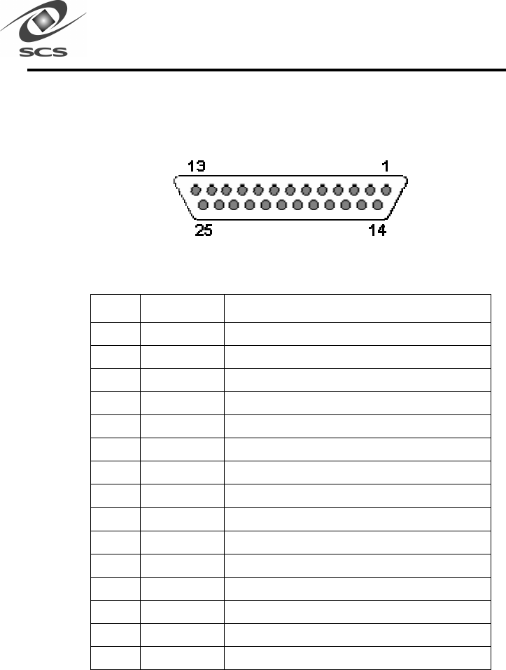
1 GND Ground
2 BUFCOMP Digital test signal: output of receiver comparator
3 GND Ground
4 PER_IN2 Peripheral input bit 2
5 PER_IN0 Peripheral input bit 0
6 PER_OUT6 Peripheral output bit 6
7 PER_OUT4 Peripheral output bit 4
8 TX_ASEL5 Transmit antenna select bit 5
9 TX_ASEL3 Transmit antenna select bit 3
10 TX_ASEL1 Transmit antenna select bit 1
11 RX-ASEL5 Receive antenna select bit 5
12 RX-ASEL3 Receive antenna select bit 3
13 RX_ASEL1 Receive antenna select bit 1
14 VCC +5 volts
15 BUFCOMPIN Analog test signal: input to receiver comparator
Chapter 6Chapter 6
Chapter 6Chapter 6
Chapter 6
DB-25 Connector FunctionDB-25 Connector Function
DB-25 Connector FunctionDB-25 Connector Function
DB-25 Connector Function
Table 3. .
. .
. Pin assignments: (DB-25)
DRAFT

37
Pin #
Name Function
16 PER_IN3 Peripheral input bit 3
17 PER_IN1 Peripheral input bit 1
18 BLANK Digital test signal: blanking signal
19 PER_OUT5 Peripheral output bit 5
20 PER_OUT3 Peripheral output bit 3
21 TX_ASEL4 Transmit antenna select bit 4
22 TX_ASEL2 Transmit antenna select bit 2
23 GND Ground
24 RX_ASEL4 Receive antenna select bit 4
25 RX-ASEL2 Receive antenna select bit 2
Receive Antenna Select Lines
Pins 13, 25, 12, 24, and 11 are the high order bits of the hardware
pins that select the receive antenna. Bit 0 is kept internal to the
interrogator. These lines are used to drive external multiplexers for
multi-antenna systems. They are controlled by:
1. Setting up the antenna select table in flash memory (if necessary)
using Load Antenna Table command.
2. Issue the Set Antenna Quantity command.
3. Default mode automatically cycles through all antennas. The
interrogator will freeze at a certain antenna selection by issuing
the Select Receive Antenna command.
DRAFT

38
Transmit Antenna Select Lines
Pins 10, 22, 9, 21, and 8 are the high order bits of the hardware pins
that select the transmit antenna. Bit 0 is kept internal to the interroga-
tor. These lines are used to drive external multiplexers for multi-
antenna systems. They are controlled by:
1. Setting up the antenna select table in flash memory (if necessary)
using Load Antenna Table command.
2. Issue the Set Antenna Quantity command.
3. Default mode automatically cycles through all antennas. The
interrogator will freeze at a certain antenna selection by issuing
the Select Transmit Antenna command.
Peripheral Inputs
Pins 5, 17, 4, and 16 are TTL level inputs that can be read with the
Read Peripheral Inputs command.
* Note: VCC is nominally 5.0 volts.
Table 4. Input Characteristics
Description Min. Max. Units
2.0 VCC* Volts
Input low level voltage 0 0.8 Volts
Input signal transition
time
250 nS
Input leakage current - 10 +10 µA
Input capacitance 10 pF
DRAFT

39
Peripheral Outputs
There are 8 peripheral outputs internal to the interrogator. 4 of these are
available at the DB-25 connector: pins 20, 7, 19, and 6 can be controlled
by setting or resetting bits, 3, 4, 5 and/or 6 of the command data byte of
the Write Peripheral Outputs command. The outputs are compatible
with CMOS levels.
Table 5. Output Characteristics
*Note: VCC Min. is 4.75 volts, VCC is nominally 5.0 volts.
Description Min. Max. Units
OutputHigh
= 1.0 mA, VCC* Min.
VCC* – 0.5 Volts
Low level output voltage @I
OutputHigh
= 12.0 mA, VCC* Min.
.4 Volts
Source current - 1.0 mA
Sink current 12.0 mA
Ouput leakage current - 10 +10 µA
DRAFT

40
This is the analog output of the RF receiver. The pin must remain
unconnected, or deterioration of read capability will occur.
Buffered Comparator (BUFCOMP)
This is the digitized output of the RF receiver.
Receiver blanking signal (BLANK)
When low, the microcontroller is ignoring the output from the RF
receiver.
VCC
This is the 5.0 V regulated power for the interrogator. It should only be
used as a reference. Current drawn in excess of 50 mA may cause the
system to shut down.
DRAFT

41
Limited Warranty
SCS warrants its Dura-label to be free from defects in workmanship and materials, under
normal use and service, for a period of ninety (90) days from receipt of products.
SCS warrants its Scanner to be free from defects in workmanship and materials, under
normal use and service, for a period of 1 year from date of receipt.
If a product does not operate as warranted during its applicable warranty period, SCS
shall, at its option, repair the defective product or deliver to Customer an equivalent
product to replace the defective item. All products that are replaced shall become the
property of SCS. Replacement products may be new or reconditioned. The warranty for
replacement or reconditioned product is the same as the equivalent newly purchased
product.
SCS reserves the right to refuse to warranty repair any product that has been subjected to
any abnormal electrical, mechanical, or environmental abuse.
FCC Part 15 Compliance
The FCC has established rules that permit the scanner and tag system to be used within
acceptable bounds of radio frequency emissions. Your scanner and tag system complies
with Part 15 of the FCC Rules.
Operation of the Scanner and Label system is subject to the following conditions: This
device may not cause harmful interference; This device may accept any interference
received, including interference that may cause undesired operation.
This device complies with the limits for a Class B digital device, pursuant to Part 15. The
Class B limits help ensure that this device provides reasonable protection against
harmful interference in residential installation. This equipment generates, uses, and can
radiate radio frequency energy and, if not installed and used in accordance with the
instructions in this manual, may cause harmful interference to radio communications.
DRAFT

42
Radio Frequency (RF) exposure limits
for operators of this device
Operators of this device must have knowledge of their RF exposure conditions in order
for the device to comply with FCC-adopted RF exposure limits for persons in the
“controlled exposure environment”. (At 3”, the average RF exposure for operators is
5.0 mW/cm .) Operators should maintain an estimated separation distance of 8 cm
or 3” from the transmitter, while in operation. They should not remain closer than the
suggested distance for any continuous 6 minute interval. Holding “Tags” in front of
the transmitter for brief moments, at closer than 3” is allowed provided the average
exposure in any 6 minute interval is less than 5.0 mW/cm 2. For example, if an
operator spends 50% of the time with his/her hands or body closer than 3” to the
transmitter while spending the other 50% of the time at more than 5” away, the
allowed RF exposure limits will be satisfied. Operators should use their own judgment
to limit their exposure to the allowed RF exposure limits with control of exposure
conditions, separation distance from the transmitter, and duration of exposure. While
this device is in operation, nearby persons who have no knowledge of being in the RF
fields of this device should be at least 7” away from the transmitter in order for this
devise to be compliant with the FCC-adopted RF exposure limits.
Disclaimer
Operation of any radio transmitting equipment, including the Scanner, may interfere
with the functionality of inadequately protected medical devices. Consult a physician
or the manufacturer of the medical device if you have any questions. Other electronic
equipment may also be subject to interference.
SCS Support (858) 485-9196
8:00 a.m. – 5:00 p.m. PST
Email – techsupport@SCS-Corp.com
DRAFT

43
DRAFT