Sirius XM Radio XMCK20 XM Satellite RX and FM TX User Manual RoadyXT manual layout
Sirius XM Radio Inc. XM Satellite RX and FM TX RoadyXT manual layout
Contents
- 1. Sure Connect Installation Guide
- 2. Quick Guide
- 3. Users Guide
Sure Connect Installation Guide
Important: Be sure to read the information on pages 4 and 5 carefully to determine if the XM SureConnect
vehicle installation method is appropriate for your vehicle. Please reference the user and installation
guides for your XM Satellite Radio receiver for additional information about optional installation methods
like using the cassette adapter or Professional Wired FM.
XM SureConnect V1.5
Vehicle Installation Guide

2
FCC Information
Please note that the power cable that has been supplied with your device is supplied with
permanently attached ferrite beads. It is the responsibility of the user to use the power
cable with the ferrite beads.
The user is cautioned that changes or modifications not expressly approved by XM Satellite
Radio Inc. can void the user’s authority to operate this device.
This device complies with Part 15 of the FCC Rules. Operation is subject to the following
two conditions:
(1) This device may not cause harmful interference.
(2) this device must accept any interference received, including interference that may
cause undesired operation.
This equipment has been tested and found to comply with the limits for a Class B digital
device, pursuant to Part 15 of the FCC Rules.These limits are designed to provide reason
able protection against harmful interference in a residential installation.
This equipment generates, uses, and can radiate radio frequency energy and, if not installed
and used in accordance with the installation instructions, may cause harmful interference to
radio communications. However, there is no guarantee that interference will not occur in a
particular installation. If this equipment does cause harmful interference to radio or televi
sion reception, which can be determined by turning the equipment off and on, the user is
encouraged to try to correct the interference by one or more of the following measures:
Reorient or relocate the receiving antenna of the affected receiver.
Increase the separation between the XM equipment and the affected receiver.
Connect the XM equipment into an outlet on a circuit different from that to which the
affected receiver is connected.
Consult the dealer or an experienced radio/TV technician for help.
Warning: The FCC and FAA have not certified the receiver for use in any aircraft (nei
ther portable nor permanent installation).Therefore, XM Satellite Radio cannot support this
type of application or installation.

FCCInformation ..............................................2
Choosing the Proper XM SureConnect Installation . . . . . . . . . . . . . . . . .4
Installation Locations . . . . . . . . . . . . . . . . . . . . . . . . . . . . . . . . . . . . . . . . .5
Installation Setup Overview for Option 1 and Option 2 . . . . . . . . . . . . . 6
Option 1
External FM Antenna Coupling Clip Installation . . . . . . . . . . . . . . . . . .8
External FM Antenna Cable Routing . . . . . . . . . . . . . . . . . . . . . . . . . . . .9
Option 2
Internal OnGlass FM Antenna Installation . . . . . . . . . . . . . . . . . . . . . . 10
Internal OnGlass Antenna Bracket Installation . . . . . . . . . . . . . . . . . . . 12
Internal OnGlass Antenna Cable Routing . . . . . . . . . . . . . . . . . . . . . . .14
AdditionalInformation ........................................15
Table of Contents
3
Caution: Use your XM SureConnect accessory with only the enclosed compo-
nents and approved connectors. Do not modify wires or other connectors in
any way; you could cause a malfunction, which could damage your receiver
and will void your warranty.
Warning: This guide contains important installation information. Please read,
understand, and follow the instructions in this guide. Failure to do so could
result in personal injury, death, and/or damage to your XM Satellite Radio
receiver, accessories, and/or to your vehicle or property.
Choosing the Proper XM SureConnect Installation
4
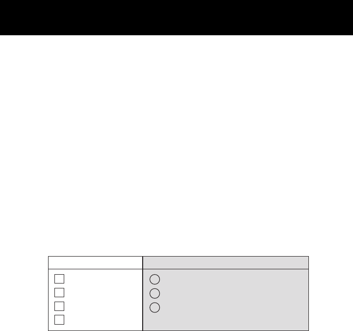
To choose the proper XM SureConnect installation method, first you need to
determine the location of your vehicle’s FM antenna, and plan how to properly
route the XM SureConnect cables to your FM antenna location.
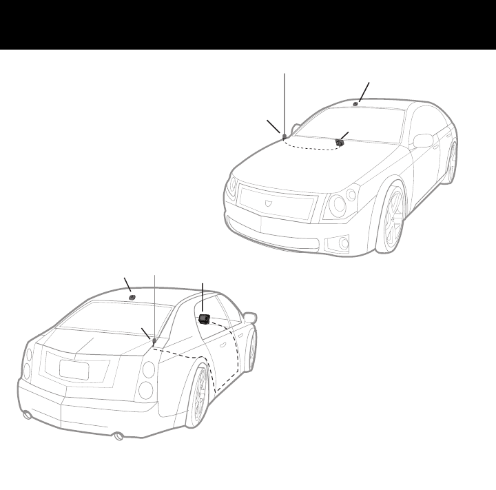
The FM antenna type and location will determine which option you will need.The
chart below and illustrations on page 5 will assist you in locating your vehicle’s
FM antenna from one of seven most common locations.
Note: XM SureConnect was not designed for use on retractable (automatic up
and down) FM antennas and some FM antennas that are custom shapes that
were designed to match the styling of the vehicle. If your vehicle has either of
these types of FM antennas, you will not be able to use the XM SureConnect
accessory. You will need to use the professional wired FM method of installation.
For best audio performance, you will either install the XM SureConnect by clip-
ping directly to an external FM antenna (locations 1 through 4) or directly on an
internal on-glass FM antenna (locations 5 through 7) using the window On-Glass
Antenna Bracket included.
1
2
3
4
Frontfender
Rear fender
Roof top front
Roof top back
Located at top of windshield
Located at top of rear window
Located on rear side glass (in some SUVs)
5
6
7
Option 1Option 2
or
ExternalFMAntenna Internal On-Glass FM Antenna
You will either use...
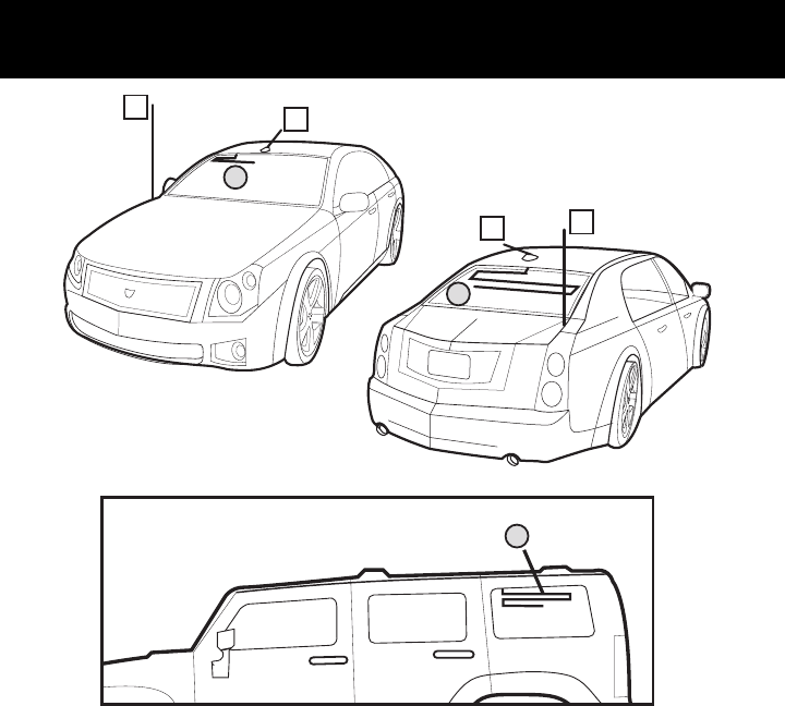
Installation Locations
5
13
42
5
6
7

TThhee ffoolllloowwiinngg sstteeppss wwiillll gguuiiddee yyoouu tthhrroouugghh tthhee iinnssttaallllaattiioonn ooff yyoouurr XXMM
SSuurreeCCoonnnneecctt uussiinngg eeiitthheerr ooppttiioonn 11 oorr ooppttiioonn 22..
1. Install your XM Radio in your vehicle as described in your XM Radio
user and installation guides.
2. Now that you have located your vehicle’s FM antenna, determine the best
routing method to get the XM SureConnect output cable to the FM antenna.
For eexxtteerrnnaall aanntteennnnaass(Figure 1b), the Coupling Clip needs to be routed
outside the vehicle. For iinntteerrnnaall oonn--ggllaassss aanntteennnnaass(Figure 1c), all routing is
inside the passenger compartment and the On-Glass Antenna Bracket is
used.
3. To route the output cable with Coupling Clip to your vehicle FM antenna,
follow the instructions on the next pages. There are separate instructions
for external antenna vs the internal on-glass antenna. Follow the instruc-
tions that apply to your vehicle’s antenna type.
NNoottee::This guide assumes you have already installed your XM antenna per
the instructions in your XM radio user guide. The positions of the XM
antenna in the illustrations on page 9 are for example only. There is no
need to change your XM antenna installation.
4. Connect the XM SureConnect input cable to the vehicle cradle’s XM line out.
Installation Setup Overview for both Options 1 and 2
6
Installation Setup Overview for both Options 1 and 2 Installation Setup
7
no boot necessary
glass
inside your
vehicle
outside
coupling
clip
External Antenna Internal on-glass antenna
boot
power
XM antenna
or
Figure 1a Figure 1b Figure 1c
Option 1 Option 2
Common connections
for both options 1 and 2
on-glass
contact bracket
Connecting the Components
XM SureConnect
Option 1: External FM Antenna Coupling Clip Installation
8
NNoottee:: IIff yyoouu ddeetteerrmmiinneedd yyoouu nneeeedd ttoo uussee OOppttiioonn 22,, ttuurrnn ttoo ppaaggee 1100 aanndd bbeeggiinn..
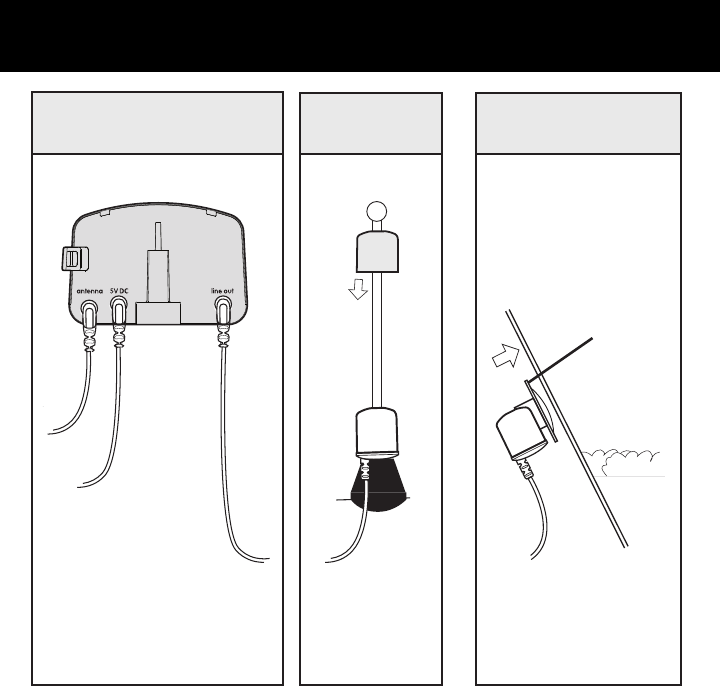
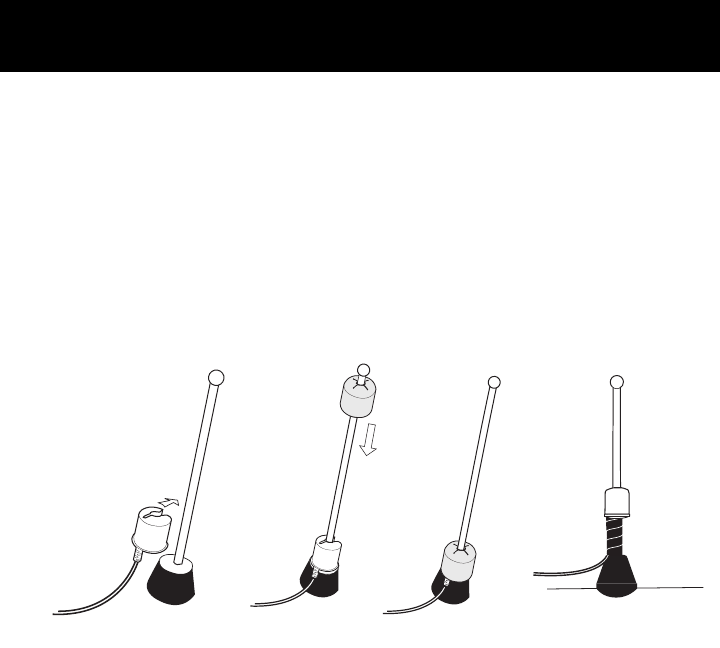
SStteepp 11::
If you have an external or roof mount FM antenna, attach the Coupling Clip
directly to the base of the antenna as illustrated in Figure 2. Cover the clip
with the rubber boot provided to protect and secure the clip. Secure the cable
inside the trunk or hood to avoid interference or accidental damage. Installing
the Coupling Clip first will avoid having excess cable outside the vehicle.
a. Snap the Antenna Coupling Clip into place.
b. Slide the boot over the top of your antenna.
c. Slide the boot down the antenna so it covers the clip.
car
antenna
rubber
boot
coupling
clip
(a) (b) (c)
NNoottee:: You may want to
use the optional cable
wrap for a more secure
solution.
Figure 2
External FM Antenna Cable Routing
9
In the front, route the cable across
the weather seal near the bottom
of the door to reduce water leaks.
Once inside the car, tuck the XM
SureConnect output cable into the
door jam up to the dash or under
the carpet as shown in Figure 3.
XM car
antenna XM
receiver
coupler
clip
In the rear, always cross the weath-
er seal at the lowest part of the
trunk to reduce water leaks. Route
the cable from the trunk into the
vehicle through available wire
channels. Next, route through the
rear passenger compartment. Tuck
the cable under the door jam trim
or under the carpet to the XM
Receiver as shown in Figure 4.
XM car
antenna
XM
receiver
coupler
clip
Figure 3
Figure 4
NNoottee::XM antenna cables are not illustrated.
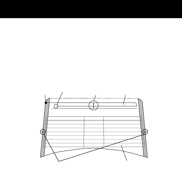
single
contact
dual contact
open ends vertical
element non-uniform
spacing
uniform spacing
FM Antenna
Rear Window
(may be hidden)
(may be hidden)
DO NOT PLACE ON DEFOGGER
Identifying the OnGlass FM Antenna in Your Vehicle
UUsseeffuull IInnffoorrmmaattiioonn ffoorr SStteepp 11::
CCAAUUTTIIOONN:: Do not attach the On-Glass Antenna Bracket to the rear defog-
ger elements. In some vehicles they look similar to the FM Antenna.
You can distinguish the FM Antenna Elements from the Defogger Elements
by several key features. See Figure 5.
Option 2: Internal OnGlass FM Antenna Installation
10
Option 2 (continued)
Figure 5

1. The FM antenna is typically found on the top 6 to 8 inches of the rear
window while the Defogger is located below.
2. The FM antenna has open ends (connected to nothing) and the
Defogger does not.
3. The FM antenna will have a single contact point and the Defogger will
have two, which are typically on opposite sides of the window. The
contact points may be hidden behind interior liners or exterior glass
tinting but the key is to locate where the elements extend beyond the
window edge. The FM antenna will have only one location while the
defogger can have two or more.
Option 2: Internal OnGlass FM Antenna Installation Option 2 (continued)
11

Internal OnGlass FM Antenna OnGlass Antenna Bracket
Installation
12
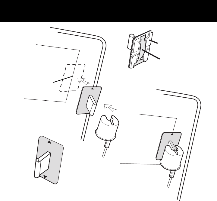
Step 1:
Install the On-Glass Antenna Bracket on the interior window surface over the antenna
element using the adhesive pad provided and the following steps. It may be mount-
ed either vertical or horizontal depending on the portion of the antenna element most
easily accessed. Select a bracket position that allows room to attach the Coupling
Clip and cleanly run cables without blocking the driver’s view. Install the on-glass
antenna Coupling Clip before routing the cable to avoid excess cable. See Figure 6.
a. Clean the mounting location on the glass for the On-Glass Antenna Bracket with
any household window cleaner that will remove grime. Be sure the surface is
completely dry before proceeding. You may need to use your vehicle’s air
conditioning and/or defogger to keep the cleaned surface dry during the
installation for the adhesive to set properly.
b. Remove the yellow liners from each of the four adhesive pads and press the
On-Glass Antenna Bracket firmly to the identified mounting location on the glass.
You can also view the alignment through the glass from outside the vehicle. You
will have only a limited amount of time to reposition the On-Glass Antenna
Bracket before the adhesive cures.
c. The On-Glass Antenna Bracket has alignment arrows on the side opposite the
adhesive pads. These arrows indicate the contact strip location on the base of the
bracket. Align the arrows with the on-glass antenna element to ensure direct
contact between the strip and the element. Press and hold the On-Glass Antenna
Bracket in place for 10 to 15 seconds.
d. Once the Bracket is in place, attach the Coupling Clip to the On-Glass Antenna
Bracket as shown in figure 6. Route any excess cable behind liners for a
professional look.
NNoottee::Be sure to leave enough slack on the cable so that the contact
strip does not pull away from the on-glass antenna.
Internal OnGlass FM Antenna OnGlass Antenna Bracket
Installation
OnGlass Antenna Bracket and Coupling Clip Installation (cont.)
13
contact strip
adhesive pads
antenna element in
glass
no boot
required
(a)
(b)
(c)
(d)
On-Glass Contact Bracket
with arrows for alignment
Figure 6
Clean this area.
Must be dry.
Internal OnGlass FM Antenna Cable Routing
coupler clip
with contact
bracket
internal on
glass
antenna
XM car
antenna XM
receiver
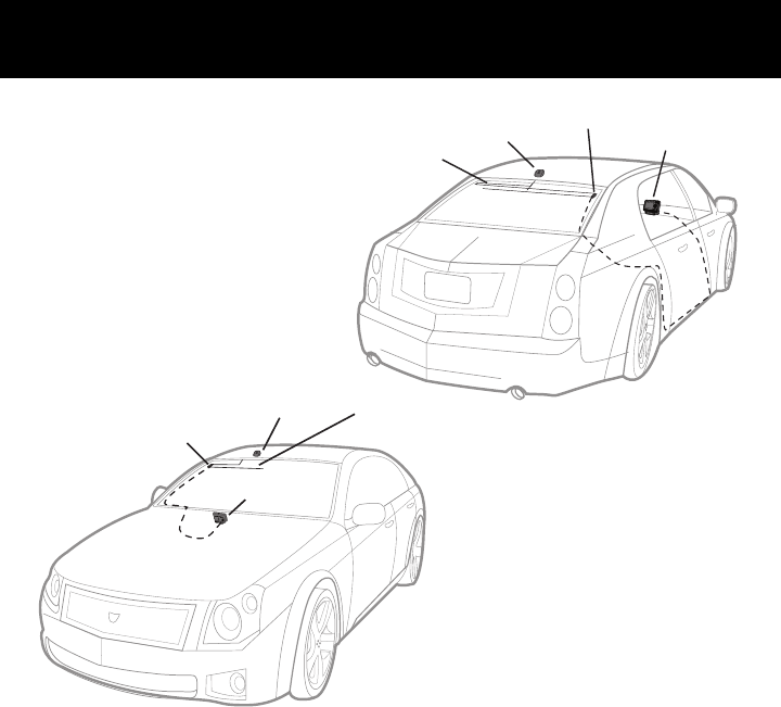
Step 2:
In the rear, route the XM
SureConnect output cable from
the antenna element, along the
window edge, down to the win-
dow liner. From the rear passen-
ger compartment tuck the cable
under the carpet or door jam
trim until you reach the front
dash area, ending at the XM
Receiver. (See Figure 7.)
XM car
antenna
XM
receiver
coupler clip
with contact
bracket
internal on glass
antenna
In the front, route the XM
SureConnect output cable from
the antenna element, along the
windshield edge, down to the
window liner along the floor and
up to the dash as shown in
Figure 8.
Figure 7
Figure 8
14 NNoottee::XM antenna cables are not illustrated.

NNoottee:: When routing the XM SureConnect cable use pre-existing wire channels
whenever possible to avoid loose wires on the interior of the vehicle which are
susceptible to damage and to maintain a professional looking installation.
Route cable carefully by taking notice of how doors open and close, as well as
how seats move when they are adjusted so you can be certain there is ample
clearance provided for the cable.
Avoid inadvertent damage that may be caused by kinking, crimping, twisting or
chafing the cables. Secure and tie wrap the excess cable under your dash
board, between the seat and the console, or on the floor under a seat or floor
mat. Securing the excess cable will help to prevent it from interfering with the
everyday use of your vehicle, improve the appearance of the installation, and
avoid any undesirable accidental damage to the cables that might result in loss
of satellite signal or XM SureConnect performance.
Important Information:
- When attempting to remove the XM SureConnect from either method of
installation, be sure to remove the “boot” first if applicable and pull the
Coupling Clip away by lifting from the end where the cable enters the clip.
Squeezing the Coupling Clip in the middle may pinch the contacts inside
and make removing the clip more difficult.
- Once installed, if you experience interference problems with your AM
reception, your vehicle’s electrical system may require you to unplug the
power adapter when your XM Satellite Radio is not in use.
- If you installed the XM SureConnect using Option 1, it is recommended
that you use brushless or touchfree car washes or hand wash your vehicle
to avoid damaging the XM SureConnect or your vehicle. Follow the infor-
mation provided by the vehicle manufacturer for instructions on removing
the FM antenna.
Additional Information
15

© 2007 XM Satellite Radio Inc.
The XM name and related logos are trademarks of XM Satellite Radio Inc.