Skidata ASX70ICV2 Inductive Tag Reader for Turnstile User Manual
Skidata AG Inductive Tag Reader for Turnstile Users Manual
UserManual.wiki
>
Skidata
>
ASX70ICV2 User Manual
Users Manual
Navigation menu
Upload a User Manual
Namespaces
Wiki Guide
HTML
PDF
Info
Views
User Manual
Discussion / Help
Navigation
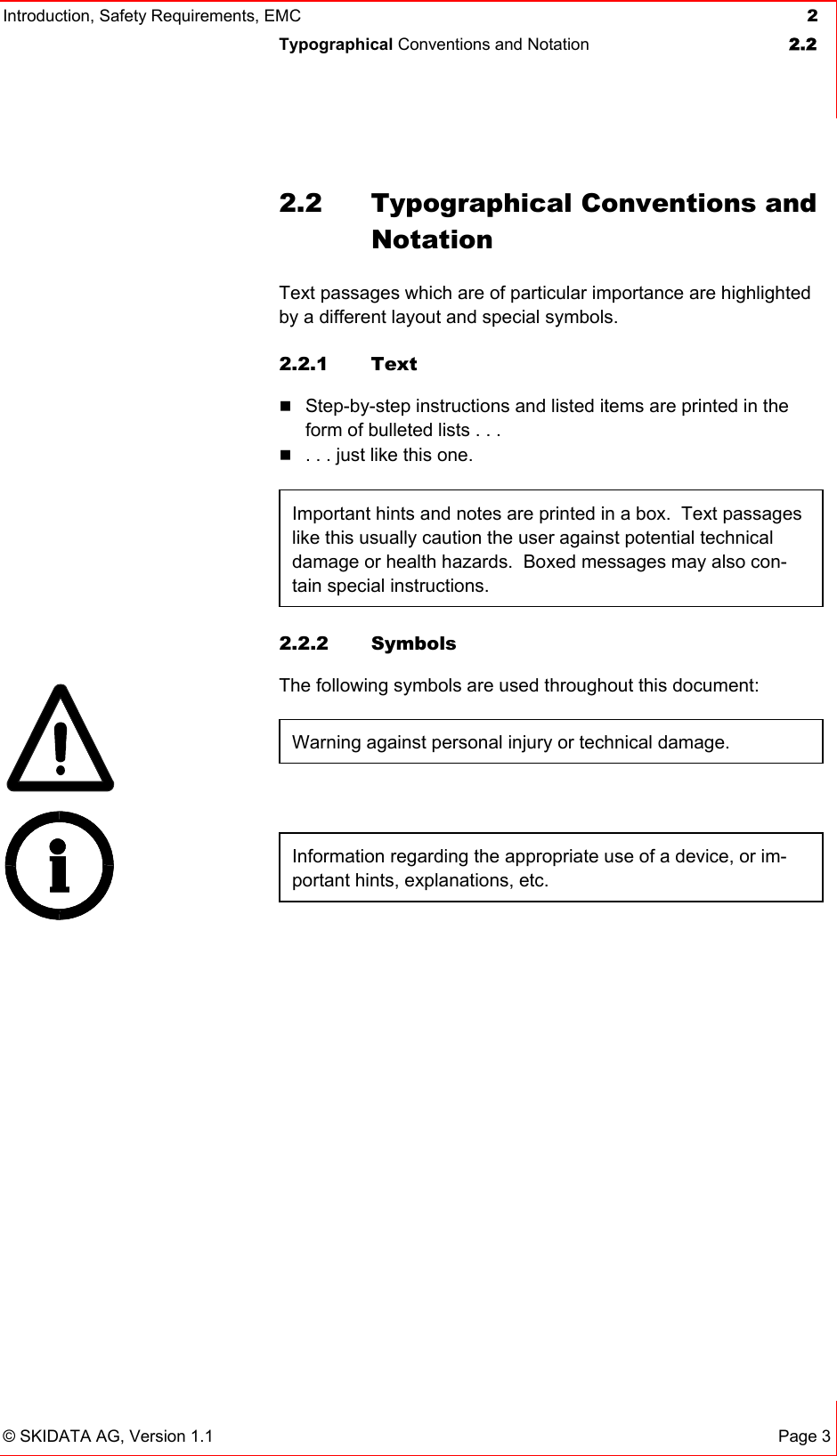
![Introduction, Safety Requirements, EMC 2 Safety Instructions 2.3 © SKIDATA AG, Version 1.1 Page 5 the general recommendations for the use of electromagnetic de-vices in addition to the following guidelines: Persons affected by these guidelines (e.g., pacemaker wear-ers) are not allowed to place keycards or other contactless (electronic) access control data carriers next to the implant when passing an access device. When passing through an access gate, a minimum distance of between 20 and 30 cm should be kept between the an-tenna and the implant (to ensure this minimum distance, the use of a Swatch Access watch or Gore [s-key] gloves is rec-ommended). Wearers of medical implants such as pacemakers should avoid leaning against an antenna unit. For wearers of medical implants such as pacemakers, the time of exposure to the RF scanning signal should be as short as possible when passing through the gate at normal pace; when queue-ing, they should stand at an appropriate distance from RF-based devices. Persons experiencing problems such as dizziness or nausea when passing an antenna should leave the scanning range of the device immediately. Antennas must bear a warning label (shown in Fig. 1 below), which must be readily visible to wearers of medical devices. In addition, a warning sign with the above-mentioned safety guide-lines should be placed at every point of initial access (e.g., cash desks). Also, lift staff should receive appropriate instructions to be able to provide information and assistance if and when required. 2.3.1.2 Danger of injury by rotating parts Operators should be aware of the danger of bruising by the rotat-ing worm drive inside Turnstile DKZ x70 i and the ticket transport rollers inside Coding unit. Fig. 1: Warning label](https://usermanual.wiki/Skidata/ASX70ICV2/User-Guide-622735-Page-11.png)