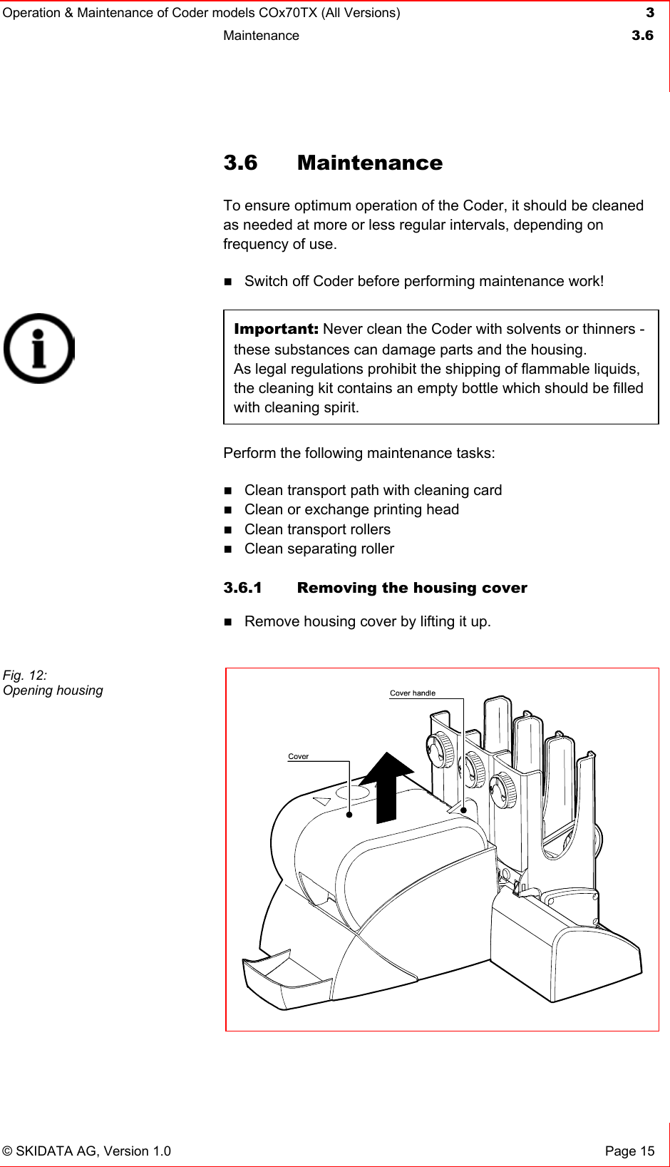
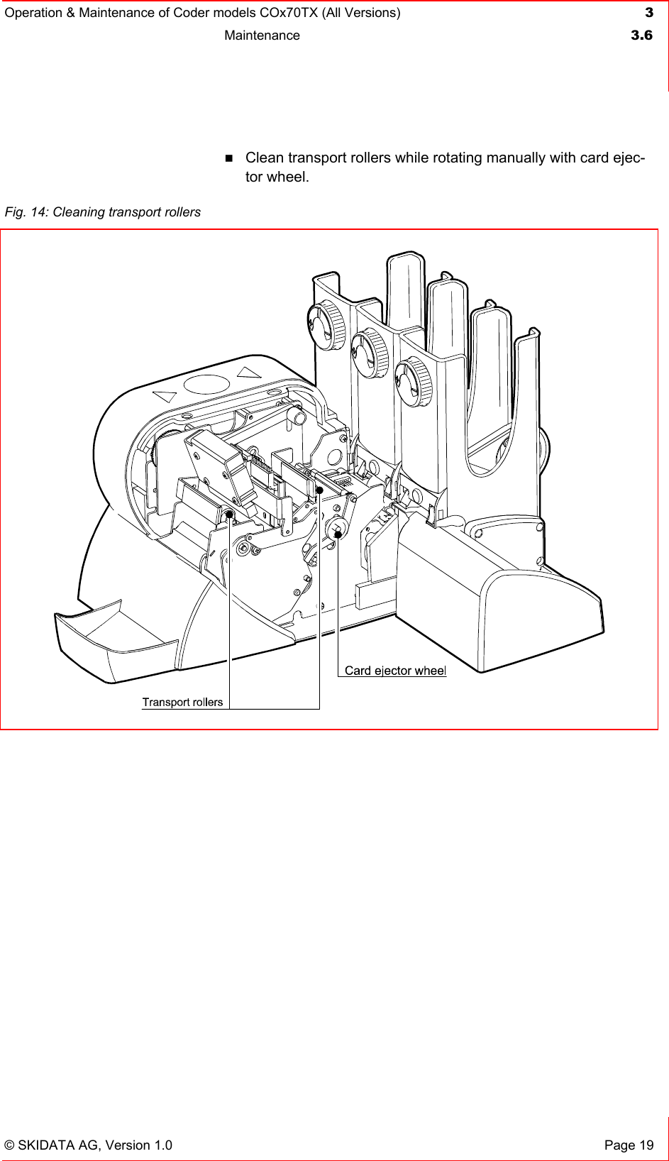
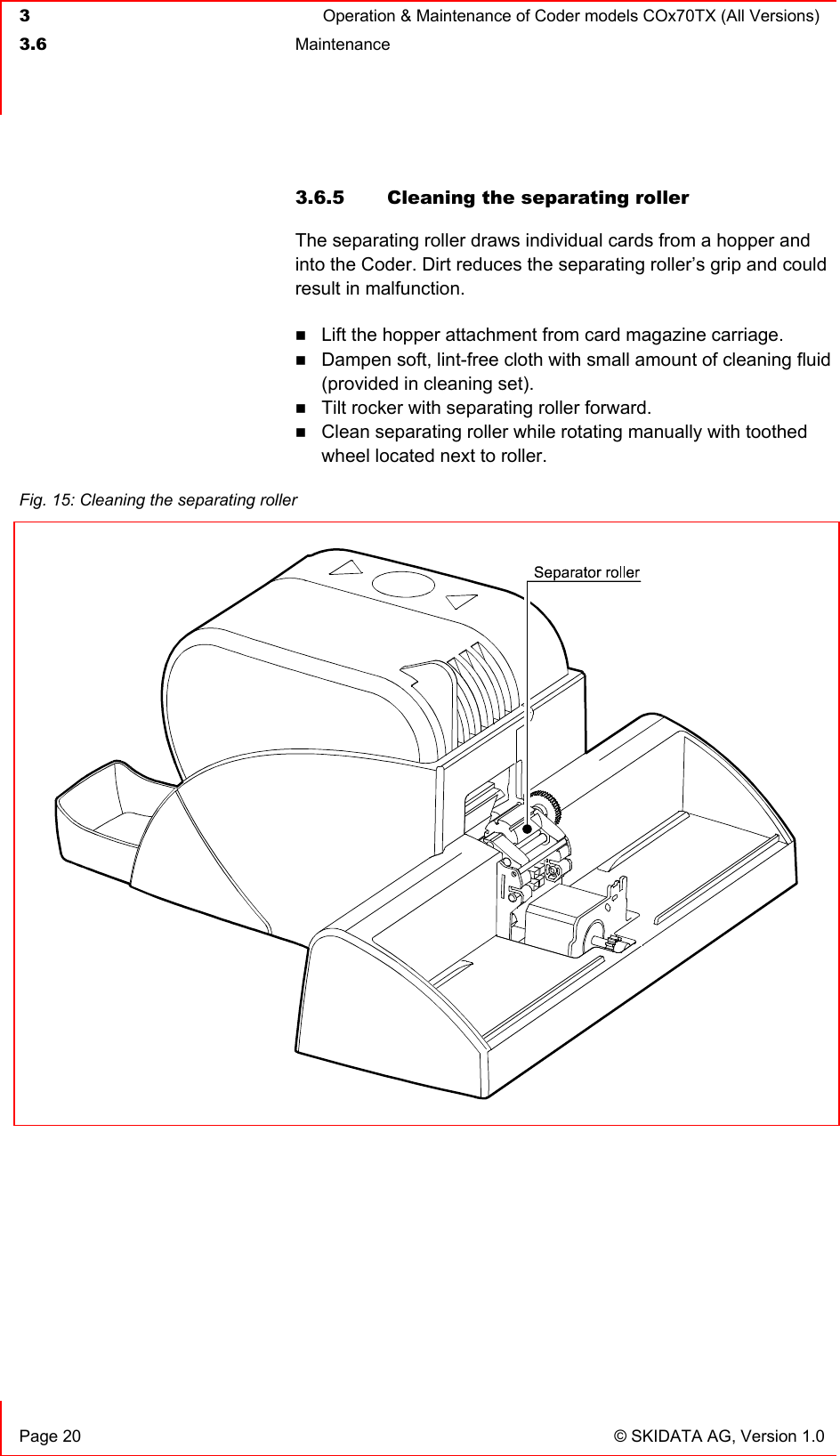
Skidata COX70ITXBC Coder working with 123 kHz and 13.56 MHz keycards User Manual COx70TX
Skidata AG Coder working with 123 kHz and 13.56 MHz keycards COx70TX
UserManual.wiki
>
Skidata
>
COX70ITXBC User Manual
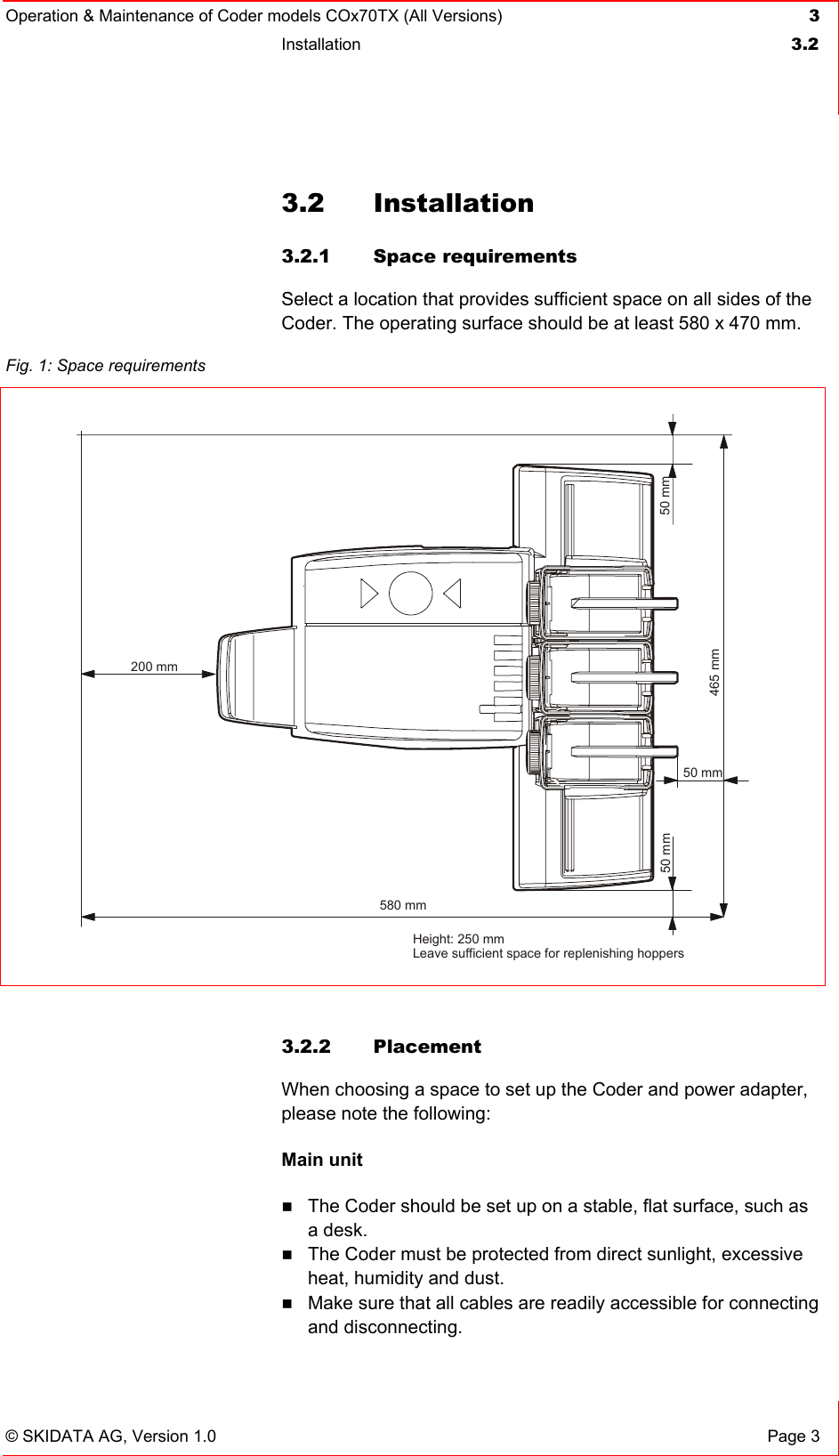
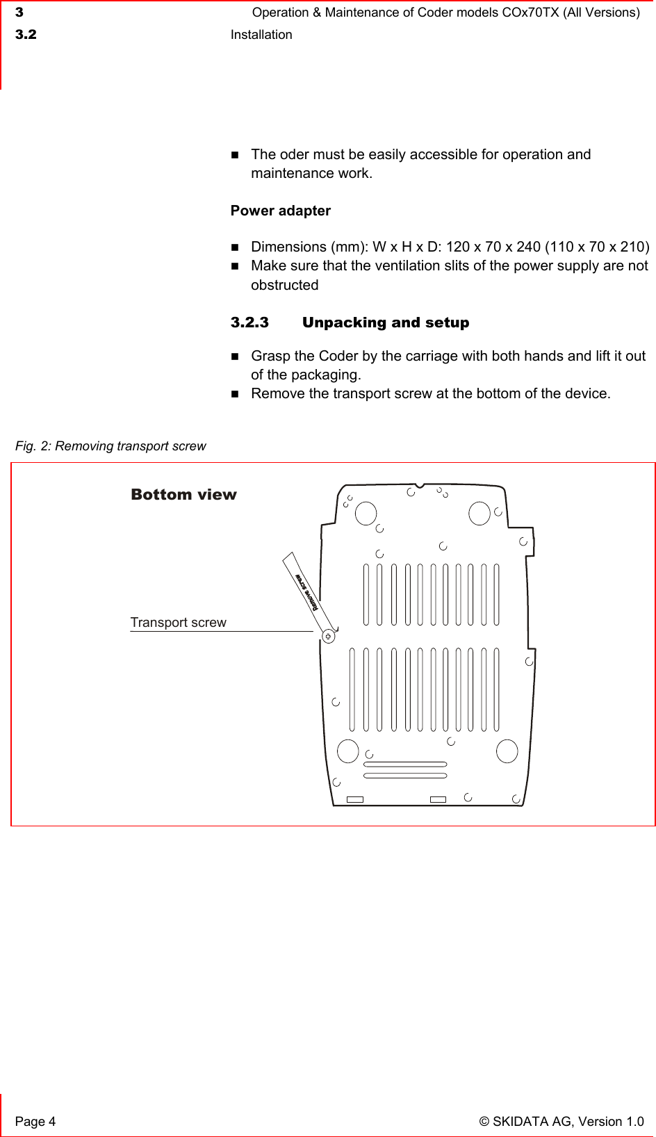
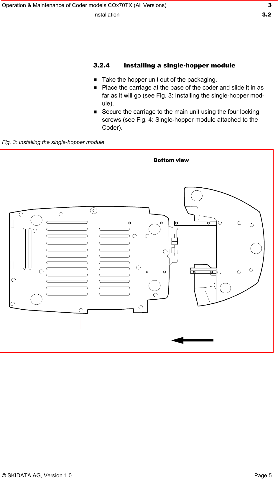
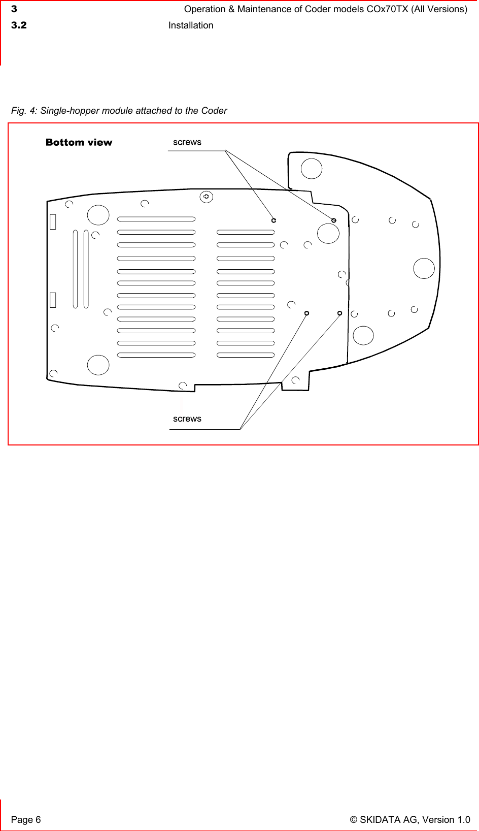
Installation Manual
Navigation menu
Upload a User Manual
Namespaces
Wiki Guide
HTML
PDF
Info
Views
User Manual
Discussion / Help
Navigation