Skidata KC370IAUT2 Keycard return machine including RFID User Manual Cover keycardReturnMachine 1
Skidata AG Keycard return machine including RFID Cover keycardReturnMachine 1
Skidata >
User Manual

Manual and operational description
keycard Return Machine
KC 370i AUT2

Manual and operational description keycard Return Machine
Page 2 © SKIDATA AG, December 2004
SKIDATA AG
Technical Documentation
Untersbergstrasse 40
A-5083 Gartenau
Telephone +43 6246 888 - 0
Telefax +43 6246 888 - 7
Internet http://www.skidata.com
e-mail docu@skidata.com
Copyright
© 2004 by SKIDATA AG. All rights reserved. All information in the
following document is protected by copyright law. No part of this
document may be reproduced without the written consent of SKI-
DATA AG. SKIDATA AG reserves the right to make any changes
of specification and other information in this document without
further notice.
Please note
During the compilation of this Technical Documentation, great
care has been taken to ensure the accuracy of the information
contained in it. However, despite our constant effort to ensure the
highest degree of accuracy and comprehensiveness possible,
the information provided cannot be guaranteed to be absolutely
error-free.
Trademarks
This documentation may contain representations of registered
product or service trademarks owned by SKIDATA AG or third
parties, as well as references to proprietary know-how protected
by copyright laws or other legal provisions. In any case the intel-
lectual property rights remain exclusively with their respective
owners.
Declaration of Conformity
The keycard-Return Machine KC 370i AUT2 has been devel-
oped, designed and manufactured in accordance with the follow-
ing EU directive:
R&TTE (1999/5/EC)
0408
Version December 2004

Keycard Return Machine Manual and operational description
© SKIDATA AG, December 2004 Page 3
FCC 15.19:
This device complies with Part 15 of the FCC Rules. Operation is
subject to the following two conditions: (1) this device may not
cause harmful interference, and (2) this device must accept any
interference received, including interference that may cause un-
desired operation.
FCC 15.21:
IMPORTANT: Any changes to or modifications of keycard Return
Machine unless expressly approved by SKIDATA™, may void the
user's authority to operate this device.

Manual and operational description keycard Return Machine
Page 4 © SKIDATA AG, December 2004
Keycard Return Machine 1
Document Management – Version Table
Tab. 1: Document Version Table for Installation & Maintenance Instructions
Section Document Pages Version Date
1 Keycard Return Machine 4 1.0 2004-12-07

Keycard – Return Machine 7
1
keycard Return
Machine
48 Pages
Copyright 2004 by SKIDATA AG

7 keycard Return Machine
1.1 Contents
Page 2 © SKIDATA AG, Version 1.0
1.1 Contents
1.1 Contents 2
1.2 Description 4
1.3 Operation 5
1.3.1 Returning keycards 5
1.3.2 Returning keycards with remaining
credits 6
1.4 Service functions 7
1.4.1 Login 7
1.4.2 Service menu 8
1.4.2.1 Reset 9
1.4.2.2 Download Firmware 9
1.5 Info Terminal 10
1.5.1 Searching the event log 11
1.5.2 Key Number 13
1.6 Dimensions 15
1.7 Front View & Description of Components 16
1.7.1 Keycard Return Machine – dimensions 17
1.7.2 Mounting 18
1.7.2.1 Mounting on wall mounting brackets 18
1.7.3 Mounting on rack stand 22
1.8 Power Connections 24
1.8.1 Connecting control board sd412 25
1.8.2 Strain relief 26
1.8.3 Heater 28
1.9 PC connections 30
1.9.1 Connectors 30
1.9.2 IPC connections (rear) 31
1.10 Replacing the keycard Container 32
1.10.1 Removing the keycard container 32
1.10.2 Inserting the keycard container 34
1.10.3 Inserting the coin cashbox 36
1.10.4 Removing the coin cashbox 37
1.11 Dispenser 38
1.12 Preparing IPC Settings 43
1.12.1 Keyboard rest 43
1.12.2 Swivelling the monitor 44

keycard Return Machine 7
Contents 1.1
© SKIDATA AG, Version 1.0 Page 3
1.13 Replacing the Mechanism 46
1.14 Closing the Bolted-open Door 47

7 keycard Return Machine
1.2 Description
Page 4 © SKIDATA AG, Version 1.0
1.2 Description
The keycard Return Machine verifies the keycard inserted by the
guest and pays out the pre-defined deposit in coins or banknotes,
depending on the machine version. Cash can be refilled by
means of easy-to-change cashboxes.
The device is controlled through an integrated PC that stores all
transactions and device status details. Peripherals such as a
mouse, keyboard and swivel-out monitor are provided for easy
servicing.
The software offers a multi-lingual graphical user interface for
easy, efficient control.
Networking the keycard Return Machines via Ethernet or modem
lines allows for remote maintenance and polling of counters and
logs (transaction tracing). If a container needs replacing, the
machine can automatically send a message to pre-defined
devices (e.g., POS stations). The End-of-Day records are relayed
to the DataCentral for inclusion in the overall statistical
evaluation.

keycard Return Machine 7
Operation 1.3
© SKIDATA AG, Version 1.0 Page 5
1.3 Operation
1.3.1 Returning keycards
The following screen message indicates that the keycard Return
Machine is fully operational and ready:
A keycard may now be inserted into the ticket slot. Once the card
has been verified and accepted, the deposit is paid out into the
change dish.
Fig. 1: Return procedure

7 keycard Return Machine
1.3 Operation
Page 6 © SKIDATA AG, Version 1.0
1.3.2 Returning keycards with remaining credits
When inserted into the front slot of the machine, the keycard is
read and verified. Any remaining credits (points, hours, etc.) will
be indicated on the screen:
The card holder may then decide whether or not to return the
card anyway. Pressing the ‘Yes’ button will initiate the return
procedure; pressing the ‘No’ button will abort the procedure and
return the card to the holder.
Fig. 2: Remaining credits
keycard Return Machine 7
Service functions 1.4
© SKIDATA AG, Version 1.0 Page 7
1.4 Service functions
There are two basic ways of accessing the Service menu:
1.4.1 Login
Logging on without keyboard
When performing simple maintenance tasks such as refilling
dispensers or hoppers, it is possible to access the unit using a
service card instead of entering a password with the keyboard.
Insert the service card into the card slot to bring up the Service
menu.
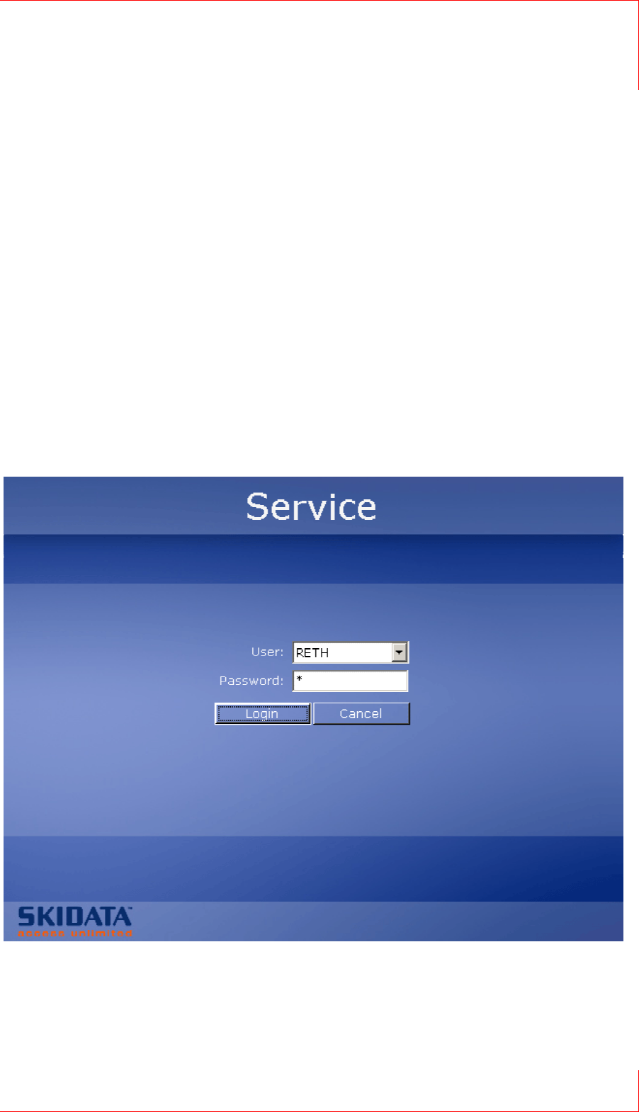
Logging on using the keyboard and mouse
Press the ‘F10’ function key on the keyboard. This will bring up
the following Login dialogue on the screen:
Enter a user name and password, then press the Tab key to shift
the focus to the ‘Login’ button and press enter (alternatively, just
click on the ‘Login’ button after entering the password).
Fig. 3: Service Logon
7 keycard Return Machine
1.4 Service functions
Page 8 © SKIDATA AG, Version 1.0
1.4.2 Service menu
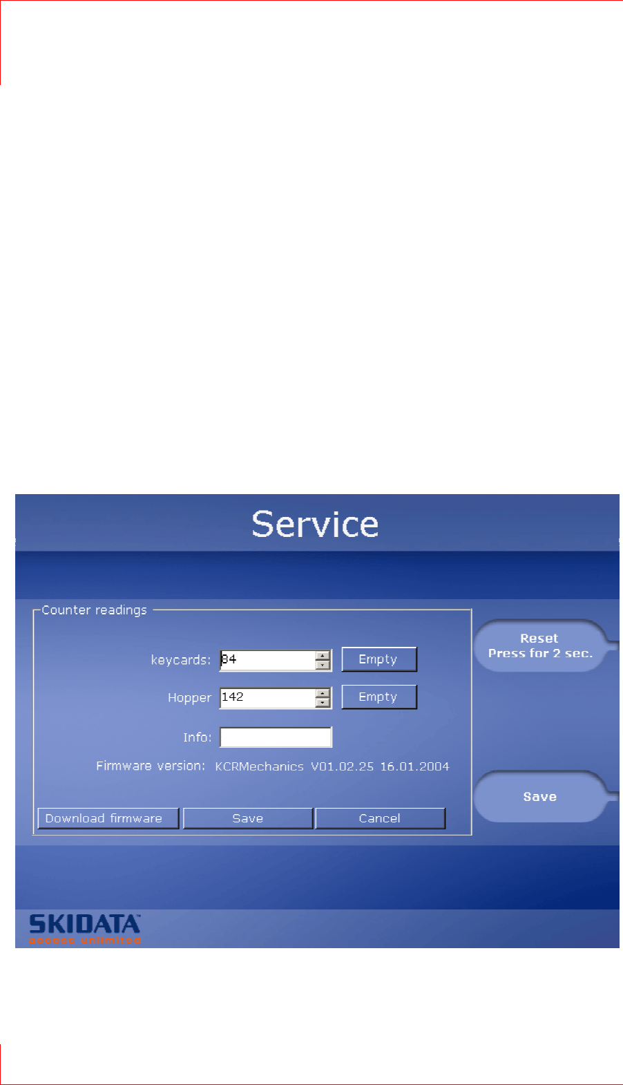
The Service menu shows the current status for the following
items:
keycard: Indicates the number of keycards in the return
container Hitting the ‘Empty’ button will set the current
keycard filling level back to zero.
Dispenser or Hopper: Indicates the number of banknotes or
coins, respectively. You may empty the hopper by clicking the
‘Empty’ button. This will cause all coins to be paid out and the
coin filling level to be reset.
The ‘Empty’ button is not available if a dispenser is used.
Info: You may enter a brief descriptive remark here (e.g.,
name of the current user). When you click the ‘Reset’ button,
the message “RESET BY EXTERNAL” will be shown in the
Info box.
Counts may also be entered via keyboard or mouse.
Fig. 4: Service menu

keycard Return Machine 7
Service functions 1.4
© SKIDATA AG, Version 1.0 Page 9
1.4.2.1 Reset
Click the ‘Reset...’ button and hold it for two seconds.
This will cause the keycard counter to be reset (i.e., cleared).
The dispenser filling level is set to a value pre-defined in the
personality firmware. ‘Old’ banknotes must then be taken out
and replaced with a new stack.
Also, the hopper level is increased by a value pre-defined in
the personality firmware (e.g., by the number of coins in a
standard roll). Refill the hopper with the pre-defined number of
coins.
Click the ‘Save’ button (or the control button next to the ‘Save’
icon) to apply the new settings. This will also close the Service
menu, and the device will return to its normal operating mode.
Hitting the ‘Cancel’ button (this requires use of the keyboard or
mouse) you can abort the procedure without applying changed
settings.
1.4.2.2 Download Firmware
This function, which is only accessible via the keyboard or
mouse, lets you download a firmware update for the Return
Machine. The current firmware version is indicated in the service
window.
Selecting the ‘Download Firmware’ button will open a file
selection dialogue. Select the file you wish to install. This will
cause the file to be downloaded and installed. An indicator bar
will show the dowload progress. When the download is finished,
the machine will return to its ready state.
7 keycard Return Machine
1.5 Info Terminal
Page 10 © SKIDATA AG, Version 1.0
1.5 Info Terminal
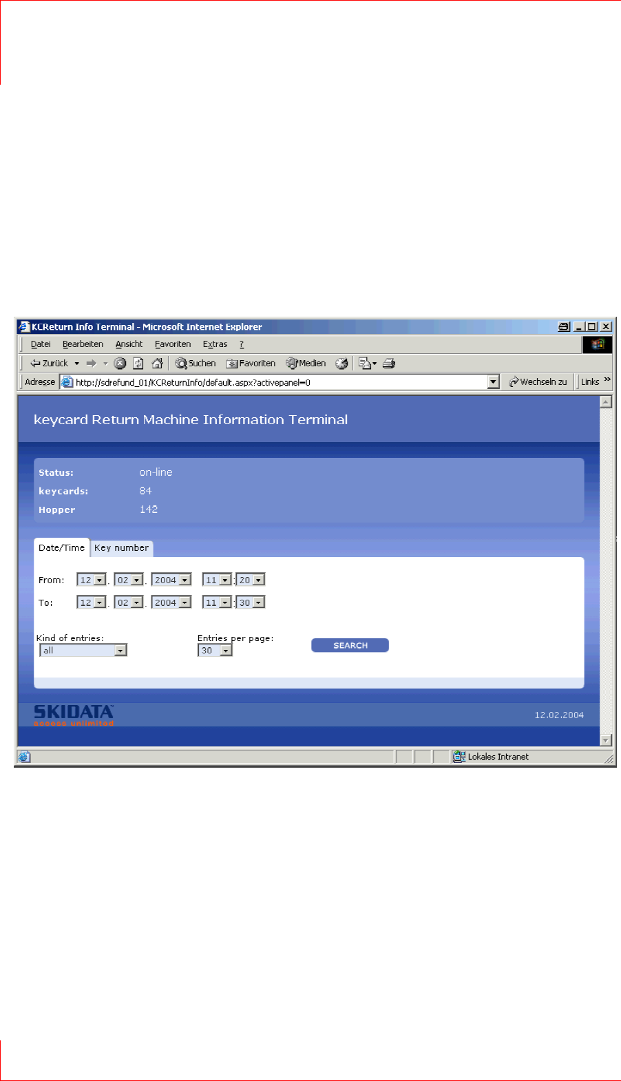
This lets you monitor the current status and operating mode of
the keycard Return Machine. This software can be run from any
PC with a network connection at the resort.
When run, the program first opens a start window showing
current system stats:
Status: In Service / Out of Service
keycards: Current keycard filling level
Dispenser or hopper: Current banknote or coin filling level
Fig. 5: Information Terminal

keycard Return Machine 7
Info Terminal 1.5
© SKIDATA AG, Version 1.0 Page 11
1.5.1 Searching the event log
It is possible to restrict the list of log entries to a specific period
by specifying dates and times.
From – Until
Enter a start and end time and date to narrow down the list of log
entries.
Kind of entries:
All: all journal entries
Errors Only: Errors that occurred when returning cards (e.g.,
incorrect residual value, wrong keycard, etc.)
Exception Errors: all servicve functions, error messages, Out
of Service notifications, etc.
Entries per page:
Specifies the number of list entries to be displayed per screen
page
Search
Hit the ‘Search’ button to apply the search filter; the list of
matching log entries will be displayed on the screen.

7 keycard Return Machine
1.5 Info Terminal
Page 12 © SKIDATA AG, Version 1.0
Fig. 6: Log entries for a specified period

keycard Return Machine 7
Info Terminal 1.5
© SKIDATA AG, Version 1.0 Page 13
Column 1:
The first column contains the line number. The background
colour indicates the type of entry.
Green: normal operation; entry shows details of read and
accepted keycards
Orange: error messages
Red: exception error messages
Columns 2 and 3
Show the date and time of events.
Column 4
Contains logged details of relevant system events. Every time a
keycard is read or accepted, its serial number is logged.
1.5.2 Key Number
On the ‘Key Number’ tab, you can enter a key no. to search the
log for matching entries.
Enter the number in the ‘Key No.’ input box and hit the ‘Search’
button.
Each matching entry will be displayed on a separate page. The
number of search results therefore corresponds to the displayed
number of pages. You can browse through the results; the list on
each page includes the 15 entries preceding the matching entry,
and the 15 entries following it. The matching entry is shown in
bold lettering.

7 keycard Return Machine
1.5 Info Terminal
Page 14 © SKIDATA AG, Version 1.0
Fig. 7: Information Terminal

keycard Return Machine 7
Dimensions 1.6
© SKIDATA AG, Version 1.0 Page 15
1.6 Dimensions
Fig. 1: keycard Return Machine – dimensions

7 keycard Return Machine
1.7 Front View & Description of Components
Page 16 © SKIDATA AG, Version 1.0
1.7 Front View & Description of
Components
10,4" LCD monitor
Softkeys
Ticket slot (illuminated)
Enclosure lock
Change tray (illuminated)
Fig. 2: Frint view

keycard Return Machine 7
Front View & Description of Components 1.7
© SKIDATA AG, Version 1.0 Page 17
1.7.1 Keycard Return Machine – dimensions
Fig. 3: keycard Return Machine – dimensions

7 keycard Return Machine
1.7 Front View & Description of Components
Page 18 © SKIDATA AG, Version 1.0
1.7.2 Mounting
Important note: The PCBs are equipped with integrated
circuits that are sensitive to electrostatic discharges. When
performing service or maintenance work on the device, be
careful not to touch any of these ICs.
Avoid any unnecessary touching of the PCBs. Before proceed-
ing with the installation, check the machine for possible trans-
port damage.
Always disconnect the device from the mains supply before
working on any of its electrical or mechanical parts.
Please note:
When mounting the device in a recessed area, ensure a
minimum wall clearance of 50 mm on both sides.
The device must be protected against rain and snow (e.g., by
means of protective roofing).
The device must not be exposed to direct sunlight.
Note the swivel radius of the door and make the necessary
allowances when mounting the unit.
Opening the device during rain or snowfalls may cause
damage to the electronic components inside.
1.7.2.1 Mounting on wall mounting brackets
General notice for wall mounting:
The wall mounting brackets may only be mounted on concrete
walls.

keycard Return Machine 7
Front View & Description of Components 1.7
© SKIDATA AG, Version 1.0 Page 19
The distance between the two consoles (hole centres) is 560
mm.
Insert 2 anchor dowels (recommended type: HILTI HST
M12/50) into the concrete wall, in accordance with
manufacturer’s instructions.
Fig. 4: Console
Fig. 5: Console

7 keycard Return Machine
1.7 Front View & Description of Components
Page 20 © SKIDATA AG, Version 1.0
Attach the consoles to the anchor dowels and fasten them
tightly with hexagon nuts and washers.
Make sure that the consoled are mounted exactly horizontally.
Using a fork lift or with the help of a sufficient number of
people, lift the machine onto the consoles. (note that the
device weighs approximately 100 kg!)
Align the machine so that the mounting holes in its enclosure
are concentric with the threaded holes in the consoles. When
doing so, make sure that the device is properly secured to
avoid personal injury or damage to the device.
Screw the supplied four M 16 threaded pins into the consoles,
with hexagon sockets facing up and hexagon nuts and
washers attached on the other end, as illustrated above.
Turn the lower hexagon nuts to adjust the enclosure until it
aligns with the surrounding wall and floor surfaces.
Place the four upper hexagon nuts and washers on the pins
and fasten them.
Check again for correct alignment of the enclosure.
Important:
Avoid drilling dust from getting inside the unit, as electrically
conductive particles may cause damage to the components.
Fig. 6: Aligning the unit
keycard Return Machine 7
Front View & Description of Components 1.7
© SKIDATA AG, Version 1.0 Page 21
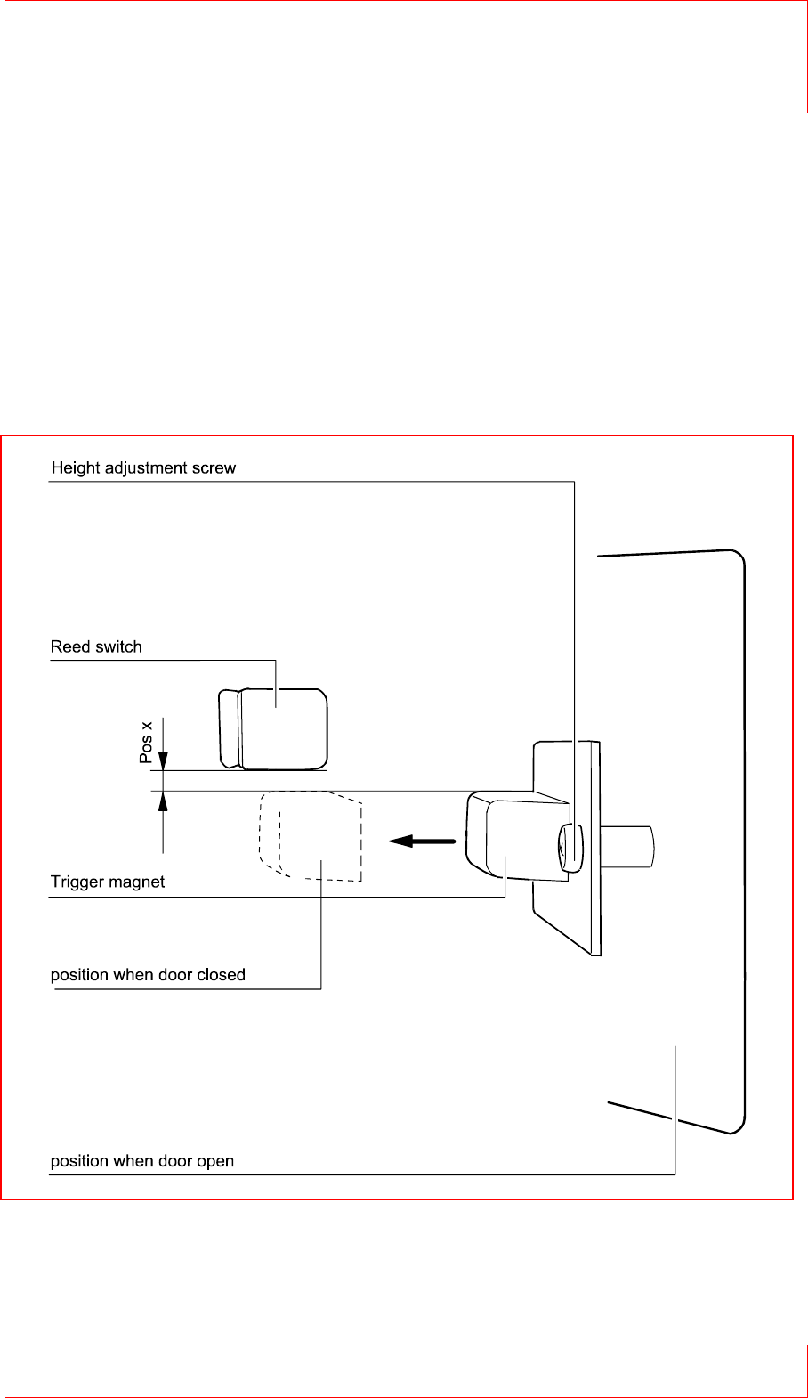
Steps to be taken after mounting: Checking the Reed swich
(Reed magnet)
Once you have installed the machine, verify that the Reed is
func-tioning correctly when closing the door. In case the switch
does not work properly, reset it to its correct position (‘X’) by
shifting the trigger magnet.
Fig. 7: Reed swich
7 keycard Return Machine
1.7 Front View & Description of Components
Page 22 © SKIDATA AG, Version 1.0
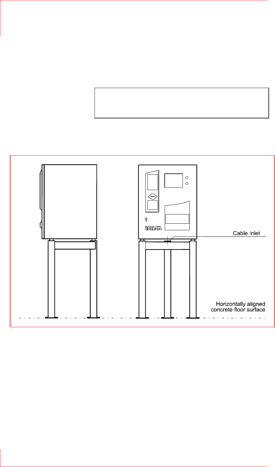
1.7.3 Mounting on rack stand
Warning notice:
The rack stand may only be installed on an appropriate hori-
zontal concrete ground surface.
Secure the rack stand to the concrete floor using anchor
dowels. In case the flooring is made from other material, make
sure that it is suitable for the weight and expected mechanical
force exerted by the device.
In case the ground surface is uneven, the rack stand should
be mounted onto glue anchors inserted into the ground. Use
washers to compensate for slants caused by the unevenness.
Using a fork lift or with the help of a sufficient number of
people, lift the machine onto the consoles (note that the
device weighs around 100 kg!)
Align the machine so that the mounting holes in its enclosure
are concentric with the threaded holes in the consoles. When
Fig. 8: Mounting on rack stand

keycard Return Machine 7
Front View & Description of Components 1.7
© SKIDATA AG, Version 1.0 Page 23
doing so, make sure that the device is properly secured to
avoid personal injury or damage to the device.
Screw the supplied 4 threaded M 16 pins with hexagon
sockets facing up and hexagon nuts and washers attached on
the other end into the consoles (see Fig. 6: Aligning the unit).
Turn the lower hexagon nuts to adjust the enclosure until it
aligns with the surrounding wall and floor surfaces.
Place the four upper hexagon nuts and washers on the pins
and fasten them.
Check again for correct alignment of the enclosure.
7 keycard Return Machine
1.8 Power Connections
Page 24 © SKIDATA AG, Version 1.0
1.8 Power Connections
Power supply:
90 V – 264 V; 47 Hz – 63 Hz
Selector switch on power adaptor (version with banknote
dispensing function only)
Wide-range voltage input (version with coin dispensing function
only)
Power: 775 W max.
Important:
Electrical installation and maintenance work may only be
carried out by qualified, licensed electricians. Power
connections must be hard-wired. Ensure full compliance with
all applicable national and international rules and directives
regarding electric connections, and all applicable safety
regulations.
Ensure the following before installing electrical connections:
Check for correct supply voltage (120 or 230 VAC)
Mains connections must comply with national standards and
directives.
When using flexible stranded wires, all filaments must be
placed inside the terminal clamps; (use wire-end sleeves as
necessary)
The mains supply line must be fused in accordance with
applicable standards.
Check the insulation resistance of the cables to make sure it
exceeds 0.5 MΩ
Cables must be fastened to the mounting the plate by way of
strain relief clamps and cable ties.
Check the network cables to ensure the proper loop
impedance.
Measure the resistance of the earth conductor to make sure it
is sufficiently low-ohmic.
Check the earth wiring of the entire electrical assembly.
Important:
Always make sure that the unit is disconnected from the mains
when working on electrical components.
keycard Return Machine 7
Power Connections 1.8
© SKIDATA AG, Version 1.0 Page 25
Note:
The type and dimension of cables must comply with applicable
national regulations in terms of the following:
– Mechanical strength
– Withstand strength
– Cross-section with regard to voltage drop
– Current load and short-circuit protection
– Heating
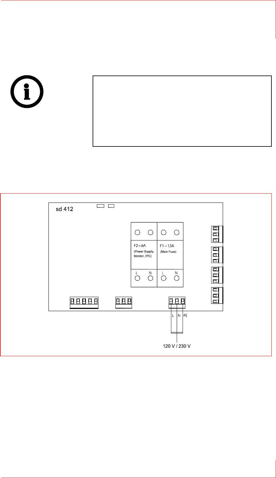
To connect the cables, you must remove the cover of sd412.
1.8.1 Connecting control board sd412
Fig. 9: Connecting sd412
7 keycard Return Machine
1.8 Power Connections
Page 26 © SKIDATA AG, Version 1.0
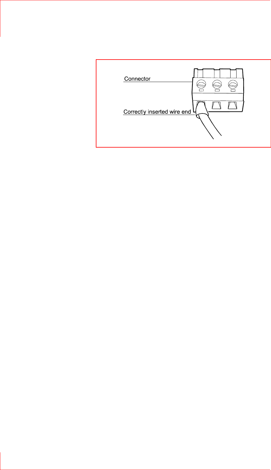
1.8.2 Strain relief
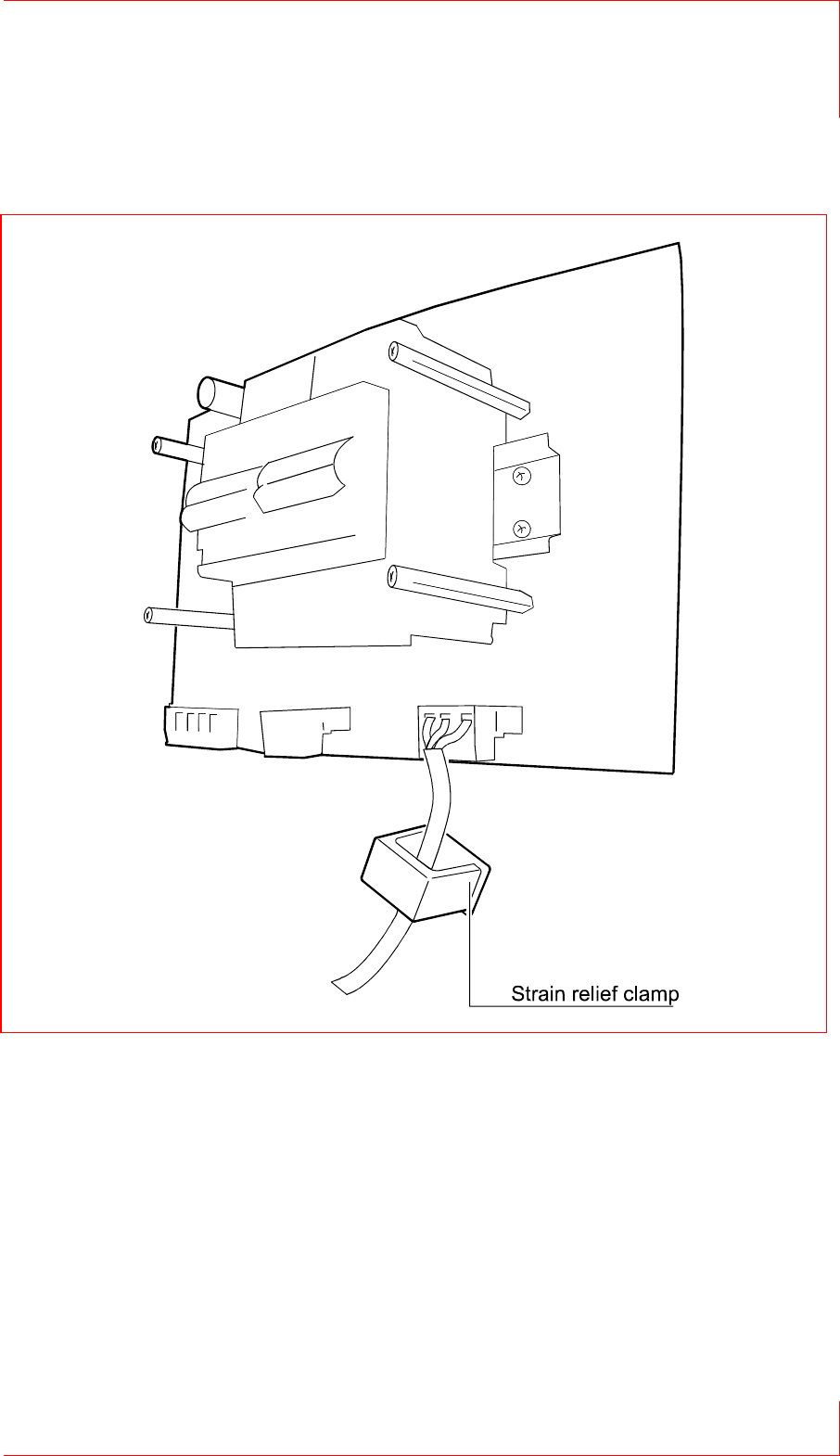
Fig. 10: Correctly inserted wire
keycard Return Machine 7
Power Connections 1.8
© SKIDATA AG, Version 1.0 Page 27
Stripping connecting wires
To prevent short circuits between conductors or between
conductors and chassis parts, wires should not be stripped by
more than 6 mm (recommended amount).
When attaching connecting wires, ensure that the insulation
covers the wire up to the metal clamp-in terminals.
Fig. 11: Strain relief

7 keycard Return Machine
1.8 Power Connections
Page 28 © SKIDATA AG, Version 1.0
Important:
After connecting the wires, check to make sure they are all
correctly attached.
Note that the torque applied to the terminals must not exceed
0.5 – 0.6 Nm
Max. cross-sectional area of conductors: 2.5 mm² / AWG 12
(rigid or flexible)
1.8.3 Heater
Important:
At ambient temperatures of 5 °C or less the front door must not
remain open for longer than 5 minutes (at most).
Setting the thermostat
The factory setting of the thermostat allows for trouble-free
operation under normal operating conditions, without any danger
of overheating.
However, if it is necessary to adjust the thermostat (e.g., in case
of extreme ambient conditions), it should be set so that the
machine cannot overheat.

keycard Return Machine 7
Power Connections 1.8
© SKIDATA AG, Version 1.0 Page 29
Fig. 12: Heater (outdoor
installation)
Fig. 13:
Heater (indoor installation)

7 keycard Return Machine
1.9 PC connections
Page 30 © SKIDATA AG, Version 1.0
1.9 PC connections
1.9.1 Connectors
Fig. 14:
Connectors: mechanism; softkey
buttons, power supply
Fig. 15:
Monitor plug-in connector

keycard Return Machine 7
PC connections 1.9
© SKIDATA AG, Version 1.0 Page 31
1.9.2 IPC connections (rear)
Fig. 16: IPC connections
7 keycard Return Machine
1.10 Replacing the keycard Container
Page 32 © SKIDATA AG, Version 1.0
1.10 Replacing the keycard
Container
1.10.1 Removing the keycard container
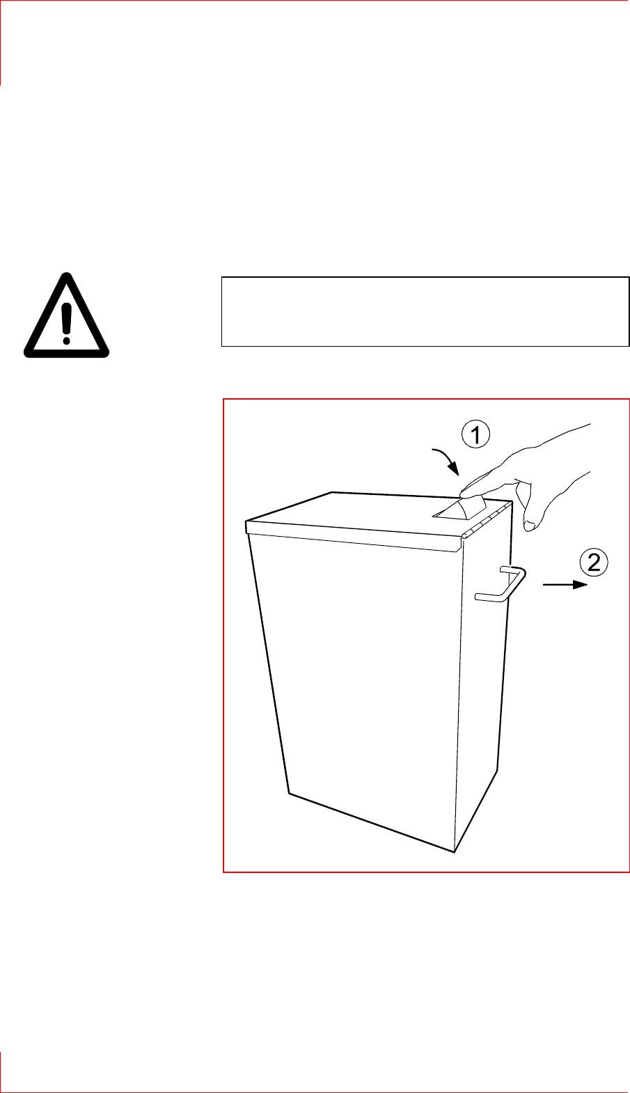
Important:
The container can only be removed if the card insert channel is
closed.
Push the card insert channel down (see illustration).
Pull out the container.
Fig. 17:
Removing the keycard container

keycard Return Machine 7
Replacing the keycard Container 1.10
© SKIDATA AG, Version 1.0 Page 33
Important:
When pulling out the container, remember that it may be quite
heavy and may cause injury if not handled properly.
7 keycard Return Machine
1.10 Replacing the keycard Container
Page 34 © SKIDATA AG, Version 1.0
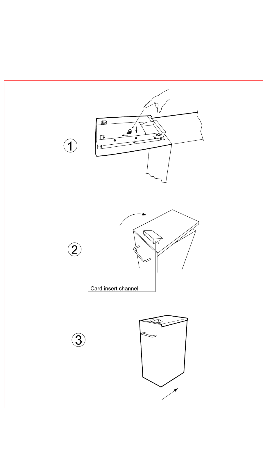
1.10.2 Inserting the keycard container
Fig. 18: Inserting the keycard container

keycard Return Machine 7
Replacing the keycard Container 1.10
© SKIDATA AG, Version 1.0 Page 35
Press the push-button down and forward, as illustrated
(arrows).
Close the cover and lock the container, making sure that the
card insert channel is completely open and unobstructed.
Push the container in as far as it will go.

7 keycard Return Machine
1.10 Replacing the keycard Container
Page 36 © SKIDATA AG, Version 1.0
1.10.3 Inserting the coin cashbox
Important:
When pulling out the coin cashbox, remember that it may be
quite heavy when full and may cause injury if not handled
properly.
Fig. 19:
Coin cashbox

keycard Return Machine 7
Replacing the keycard Container 1.10
© SKIDATA AG, Version 1.0 Page 37
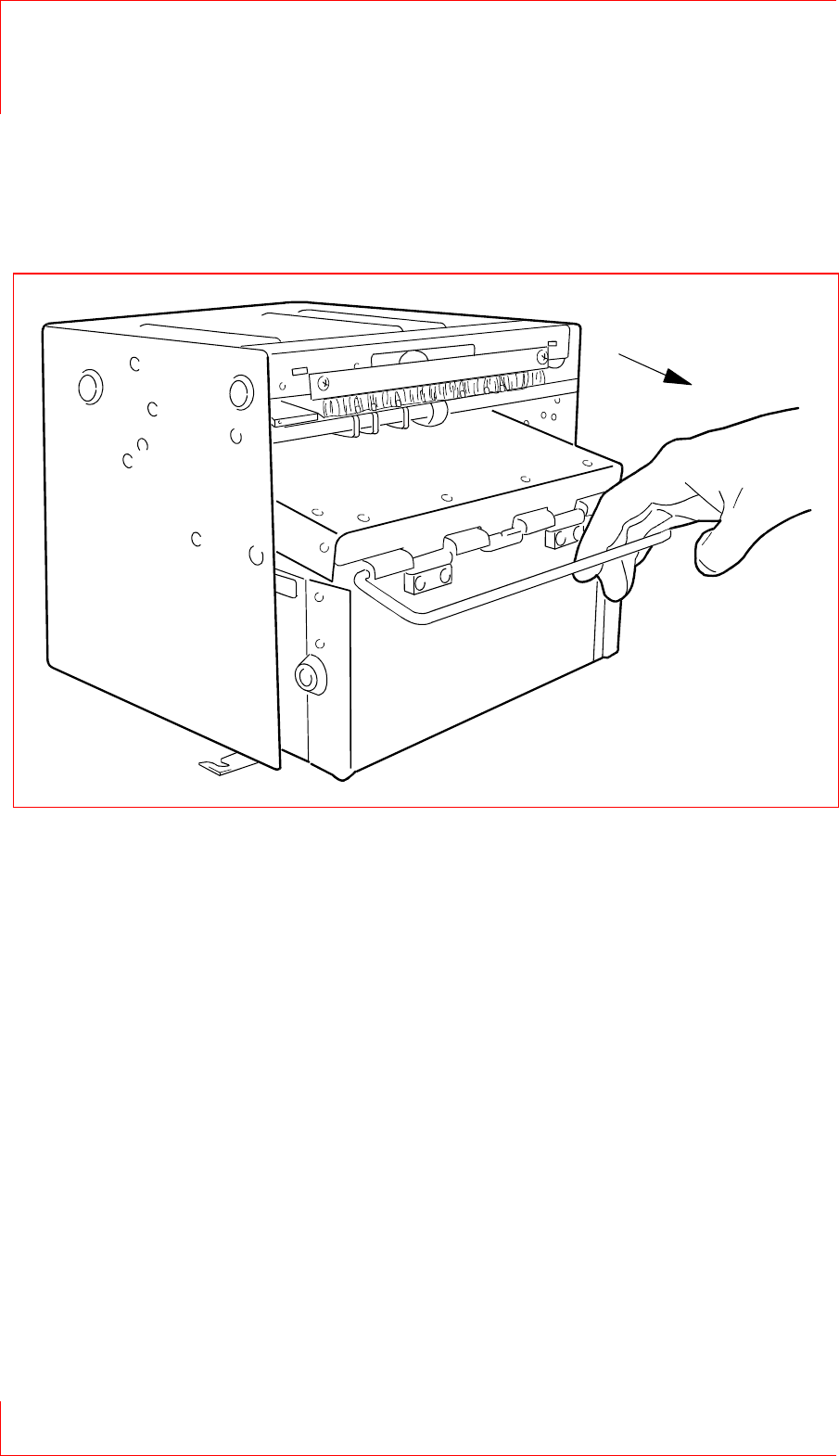
1.10.4 Removing the coin cashbox
Fig. 20:
Removing the coin
cashbox
7 keycard Return Machine
1.11 Dispenser
Page 38 © SKIDATA AG, Version 1.0
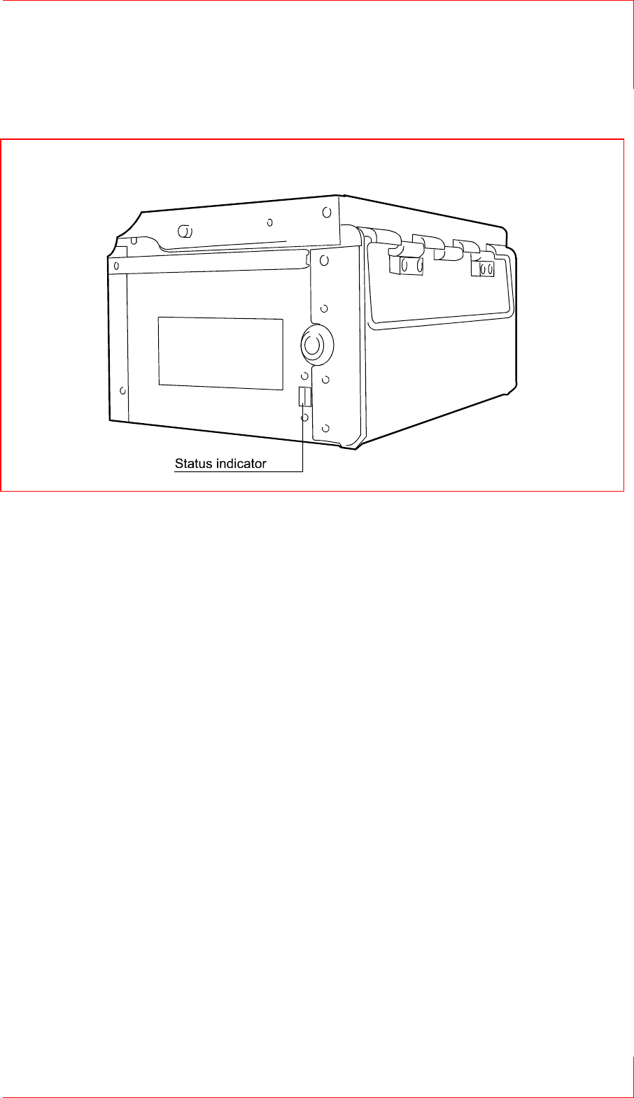
1.11 Dispenser
Fig. 21:Removing the Dispenser
keycard Return Machine 7
Dispenser 1.11
© SKIDATA AG, Version 1.0 Page 39
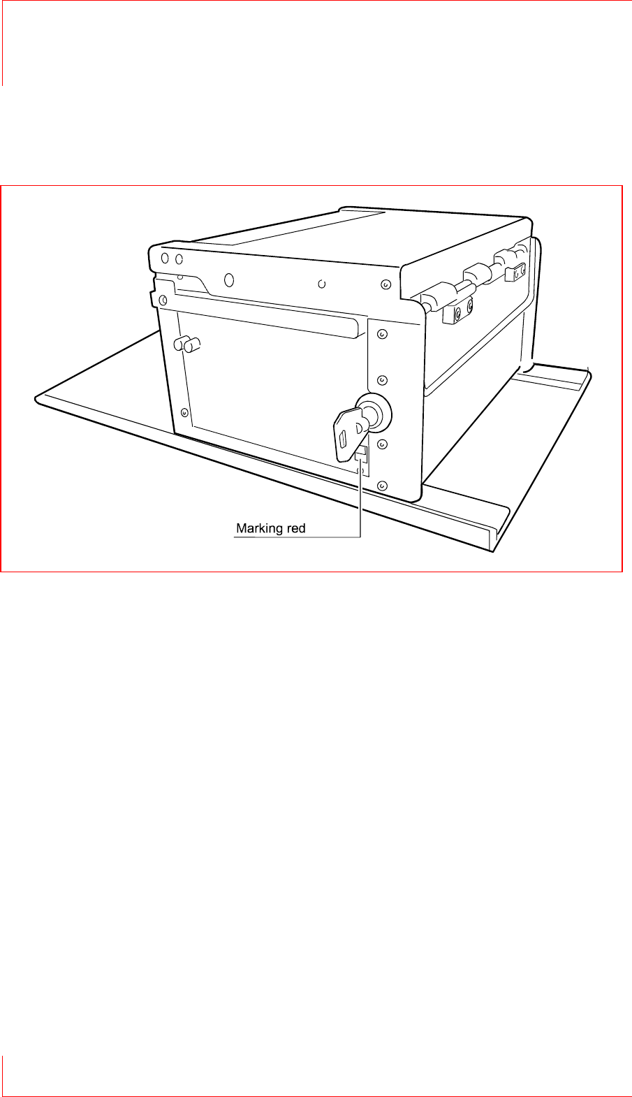
Status indicator
After removal: RED
Before inserting: GREEN
Opening the Dispenser box
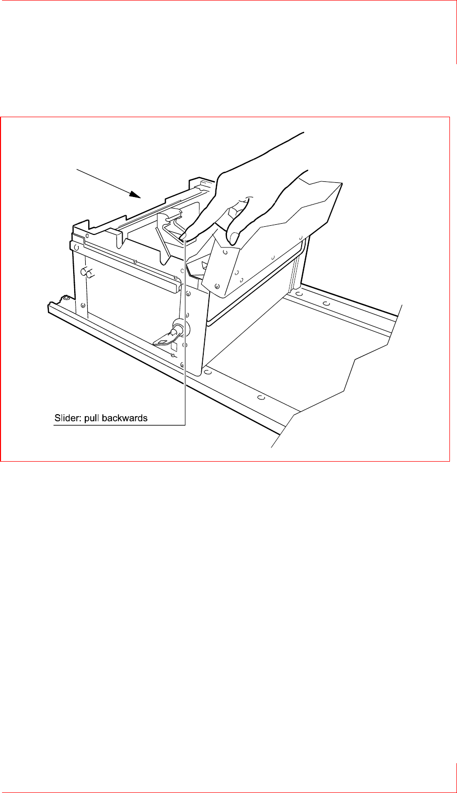
Place the box onto the unlockig rail.
Push in the box as far as it will go.
Open the box by turning the key.
Fig. 22: Dispenser box
7 keycard Return Machine
1.11 Dispenser
Page 40 © SKIDATA AG, Version 1.0
Fig. 23: Placing the Dispenser on the unlocking rail
keycard Return Machine 7
Dispenser 1.11
© SKIDATA AG, Version 1.0 Page 41
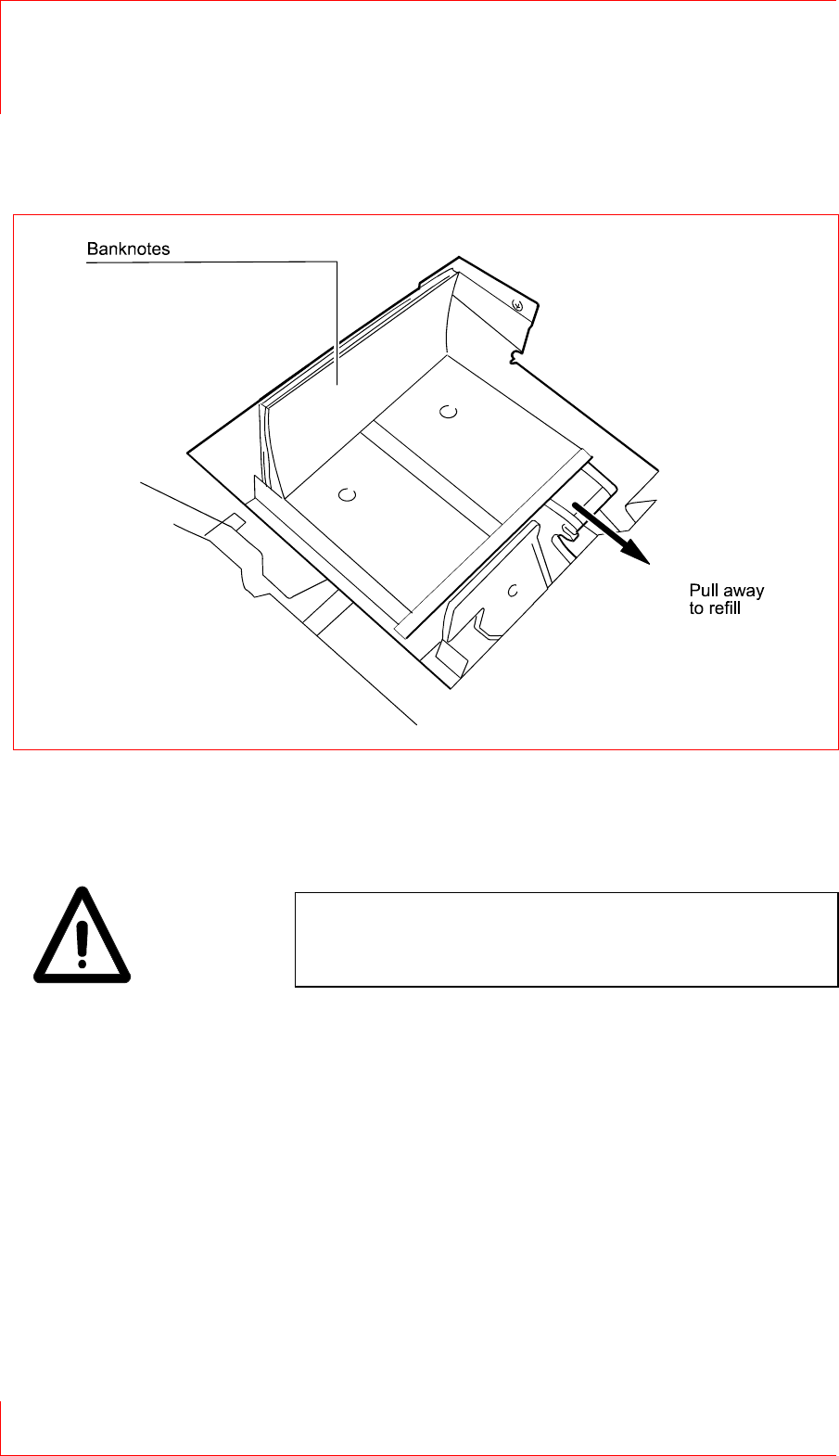
Fig. 24: Filling the Dispenser box with banknotes
7 keycard Return Machine
1.11 Dispenser
Page 42 © SKIDATA AG, Version 1.0
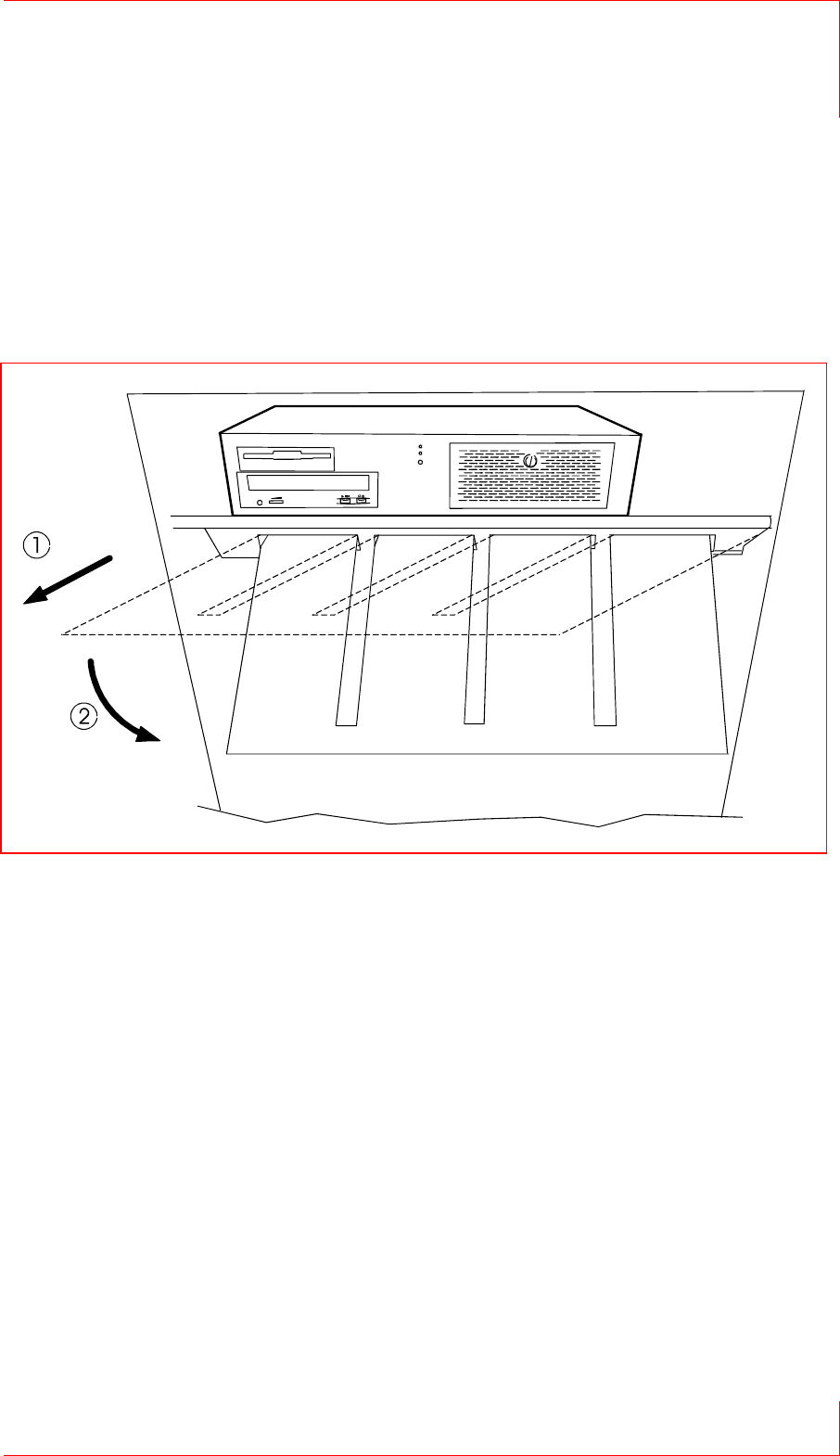
Close the cover.
The status indicator must switch to GREEN.
Important:
The Dispenser box can only be inserted when the status
indicator shows GREEN.
Fig. 25: Filling the Dispenser box with banknotes
keycard Return Machine 7
Preparing IPC Settings 1.12
© SKIDATA AG, Version 1.0 Page 43
1.12 Preparing IPC Settings
1.12.1 Keyboard rest
Pull out the keyboard rest and fold it down.
Place the keyboard on the rest.
Fig. 26: Keyboard rest

7 keycard Return Machine
1.12 Preparing IPC Settings
Page 44 © SKIDATA AG, Version 1.0
1.12.2 Swivelling the monitor
Loosen the screw by turning it counterclockwise (see item 1 in
the illustration).
Swivel out the monitor as indicated (see item 2 in the
illustration).
Important:
Avoid touching the screen surface of the LCD panel, as this
may damage the display unit.
Fig. 27: Swivelling the monitor

keycard Return Machine 7
Preparing IPC Settings 1.12
© SKIDATA AG, Version 1.0 Page 45
Fig. 28: Monitor, swivelled out

7 keycard Return Machine
1.13 Replacing the Mechanism
Page 46 © SKIDATA AG, Version 1.0
1.13 Replacing the Mechanism
Important:
Switch off the device before replacing the mechanism.
Remove the two hexagon nuts on the side panel of the
mechanism.
Fig. 29: Replacing the mechanism
keycard Return Machine 7
Closing the Bolted-open Door 1.14
© SKIDATA AG, Version 1.0 Page 47
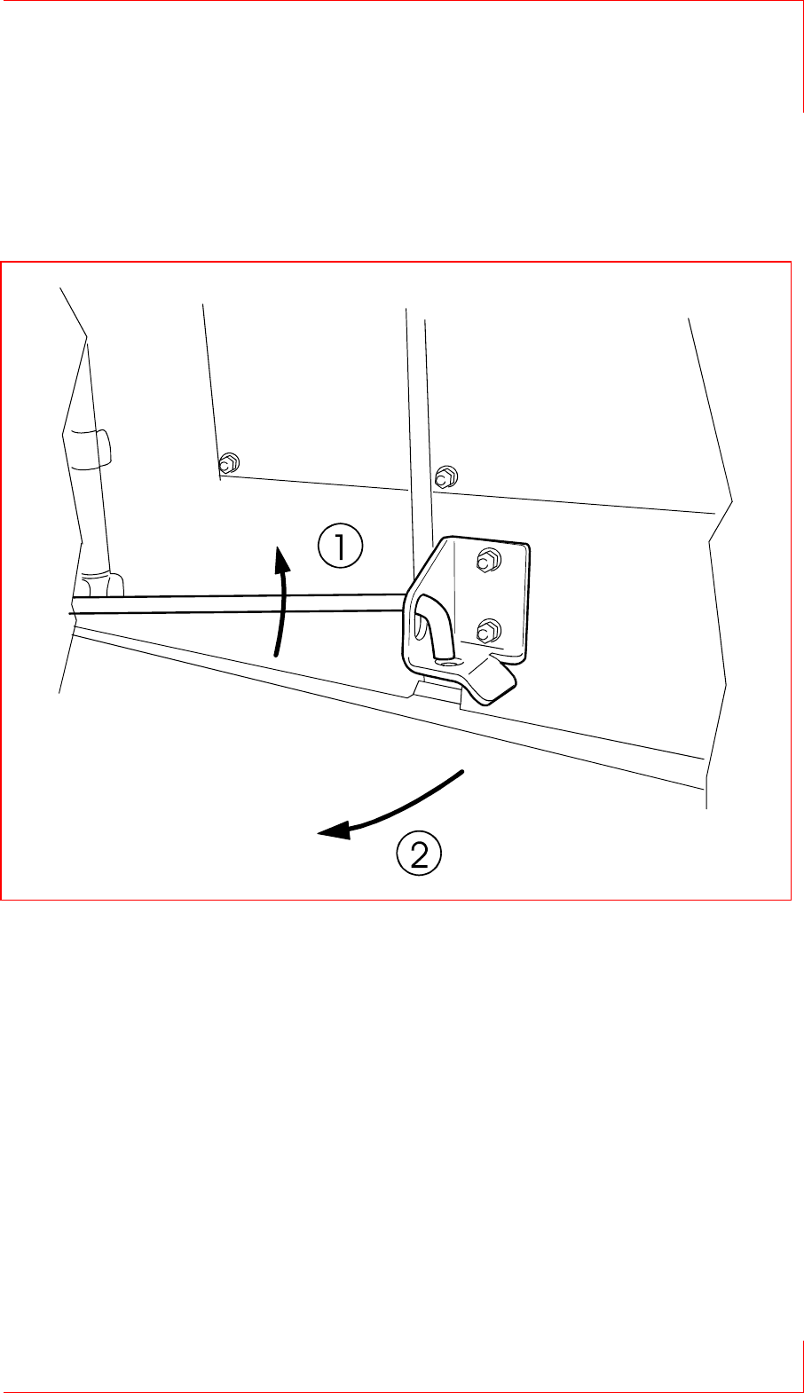
1.14 Closing the Bolted-open Door
To close the bolted-open door, lift the locking pin and close
the door.
Fig. 30: Unbolting the open door

7 keycard Return Machine
1.14 Closing the Bolted-open Door
Page 48 © SKIDATA AG, Version 1.0