Skidata KEYDDUO232 Transponder-card reader for access control User Manual Certification KeyDetector DUO
Skidata AG Transponder-card reader for access control Certification KeyDetector DUO
UserManual.wiki
>
Skidata
>
KEYDDUO232 User Manual
User manual
Navigation menu
Upload a User Manual
Namespaces
Wiki Guide
HTML
PDF
Info
Views
User Manual
Discussion / Help
Navigation

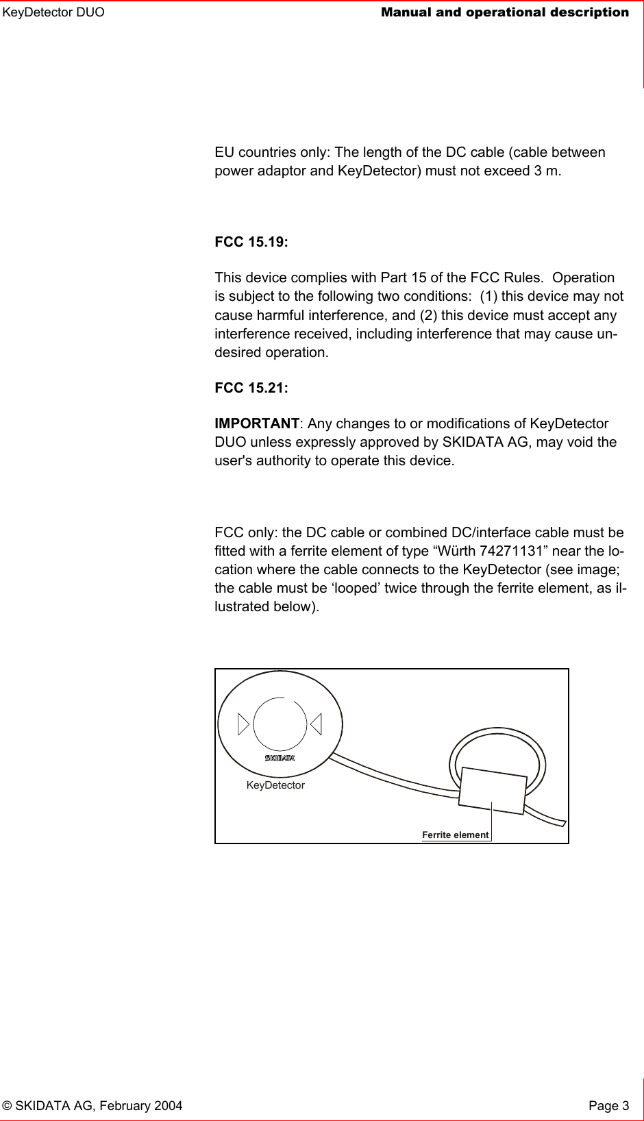
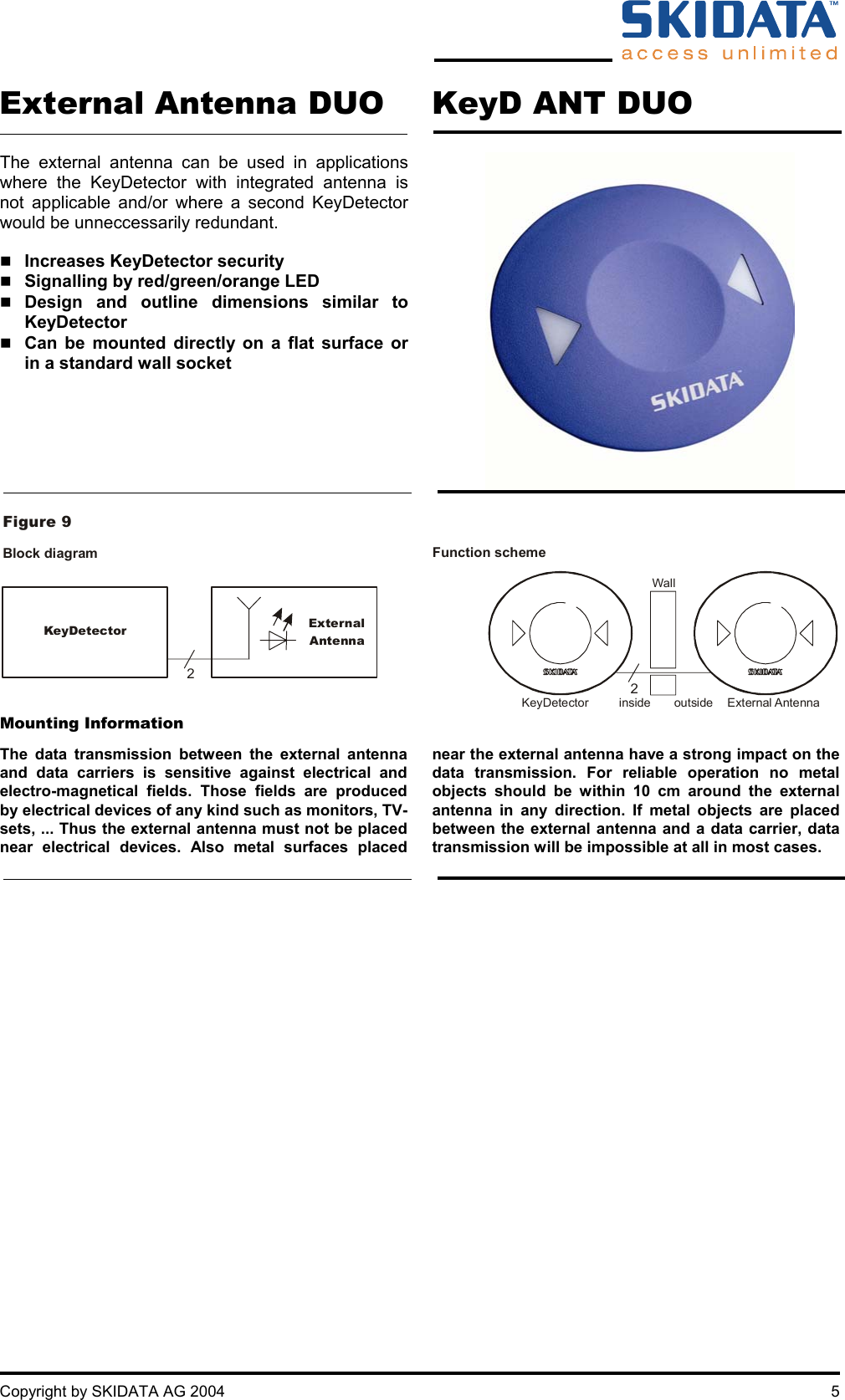
![6 Copyright by SKIDATA AG 2004 Connector for External Antenna (use connector RIACON Type 166) Terminal pin # Signal Wire Colours Function 1 ANT 13 MHz Coaxial cable inside External 13 MHz antenna 2 GND Coaxial cable shield 3 ANT 122 kHz White External 122 kHz antenna 4 GND Brown 5 LED-R Yellow LED, red or green 6 LED-G Green or orange (both) Figure 10 Main boardCable tieMetal tongueCoaxial cable RG 174 (50 for 13 MHz antennaΩ)Cable (LifYCY, 2x2x0.25 mm²)for 122 kHz antenna and LEDsConnectorfor external antenna To connect and fasten the coaxial cable - Insert metal tongue between cable shield and insulation - Fasten cable tie SKIDATA AG • Untersbergstraße 40 • A-5083 Gartenau [p] +43 6246 888-0 • [f] +43 6246 888-7 • [e] info@skidata.com • [w] www.skidata.com Version 1.0 • 2003-01-29 • Copyright © 2004 by SKIDATA AG This documentation may contain representations of registered product or service trademarks owned by SKIDATA AG or third parties, as well as references to proprietary know-how protected by copyright laws or other legal provisions. In any case the intellectual property rights remain exclusively with their respective owners. This document is subject to change without notice. It cannot form part of a binding contract.](https://usermanual.wiki/Skidata/KEYDDUO232/User-Guide-403746-Page-10.png)