SkyBell Technologies SK370-00020 2.4 GHz Wi-Fi Transceiver Module User Manual
HiTEM Engineering, Inc. 2.4 GHz Wi-Fi Transceiver Module Users Manual
Users Manual

2.4 GHz Wi-Fi Module User Manual
General Description
The 2.4 GHz Wi-Fi module is an 802.11b/g/n solution containing RF frontend circuitry, baseband, MAC,
Clock Management and Power Management for direct battery attach. The module is designed to be
Placement of FCC ID on the finished product
Use of this module requires placement of the FCC ID on the exterior of the finished product. The FCC ID
must be visible on the exterior of the product and cannot be placed on a removable part. The FCC ID
should be permanent (e.g. stamped, etched, engraved, printed with permanent ink or on a label with
permanent adhesive, etc). Hand held devices may be permitted to place the FCC ID in the battery
compartment under certain restrictions contained within KDB 784748 section 4:
https://apps.fcc.gov/oetcf/kdb/forms/FTSSearchResultPage.cfm?id=27980&switch=P
The finished product label must include the FCC ID of the incorporated module preceded by the phrase
“This device contains” or any similar such verbiage conveying similar meaning:
This device contains FCC ID: 2ADXI-SK370-00020
Or more simply:
Contains FCC ID: 2ADXI-SK370-00020
Product Label Requirement
The ID Label of the finished product must include the following statement. However, devices which are
smaller than 4x4” are permitted to place this statement in the instruction manual, pamphlet or
packaging in which the device is marketed.
“This device complies with Part 15 of the FCC Rules. Operation is subject to the following two
conditions: (1) this device may not cause harmful interference, and (2) this device must accept any
interference received, including interference that may cause undesired operation..”
Usage Restrictions
“Changes or modifications not expressly approved by the party responsible for compliance could void
the user's authority to operate the equipment.”
Manual for Products
Only one of the below statements is required to be in the finished product’s users manual, depending on
whether the product is either Class A or Class B.
Part 15 Class A Devices
“Note: This equipment has been tested and found to comply with the limits for a Class A digital device, pursuant to part 15 of the FCC Rules. These limits are designed
to provide reasonable protection against harmful interference when the equipment is operated in a commercial environment. This equipment generates, uses, and
can radiate radio frequency energy and, if not installed and used in accordance with the instruction manual, may cause harmful interference to radio communications.
Operation of this equipment in a residential area is likely to cause harmful interference in which case the user will be required to correct the interference at his own
expense.”
soldered to a PCB using with three external interfaces, power, SPI bus and u.fl antenna. The module
is designed for use within the mobile devices category with the antenna placed greater than 20 cm
from the body. The module comes fully tested and calibrated at the factory.
Part 15 Class B Devices
“This equipment has been tested and found to comply with the limits for a Class B digital device, pursuant to Part 15 of the FCC Rules. These limits are designed to
provide reasonable protection against harmful interference in a residential installation. This equipment generates, uses and can radiate radio frequency energy and,
if not installed and used in accordance with the instructions, may cause harmful interference to radio communications. However, there is no guarantee that
interference will not occur in a particular installation. If this equipment does cause harmful interference to radio or television reception, which can be determined by
turning the equipment off and on, the user is encouraged to try to correct the interference by one or more of the following measures:
-- Reorient or relocate the receiving antenna.
-- Increase the separation between the equipment and receiver.
-- Connect the equipment into an outlet on a circuit different from that to which the receiver is connected.
-- Consult the dealer or an experienced radio/TV technician for help”
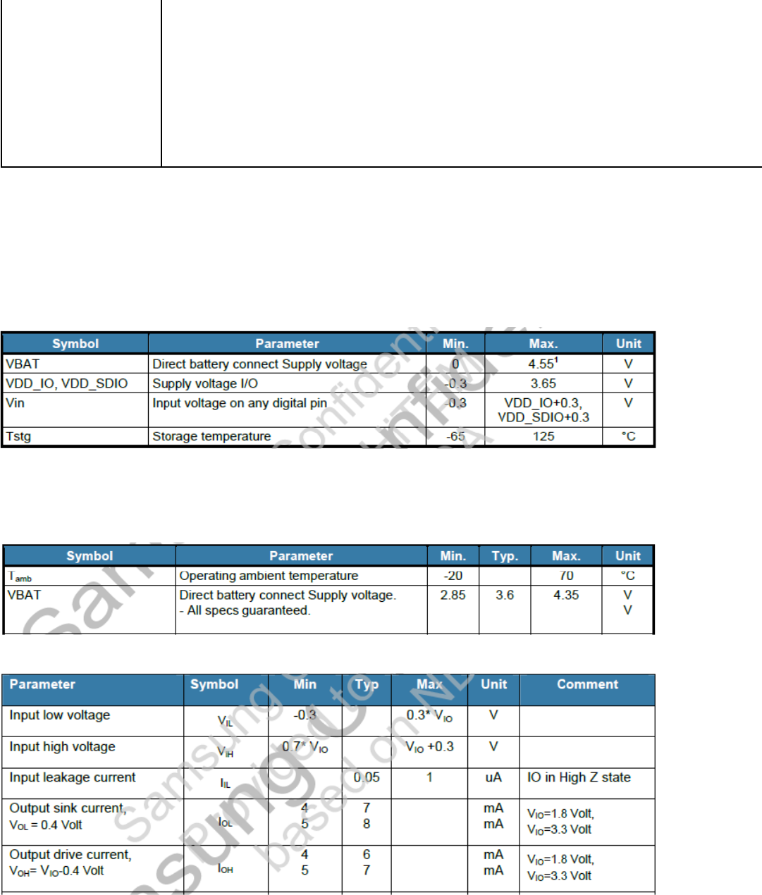
Electrical Data
Absolute Maximum Ratings
The absolute maximum ratings specify the values beyond which the device may be damaged
permanently. Exposure to absolute maximum ratings conditions for extended periods of time may
affect reliability. Each condition is applied with all other values kept within the recommended operating
condition.
Recommended Operating Conditions
The recommended operating conditions specify the values in which region the device is operational
meeting specification.
SPI Interface Electrical Specification
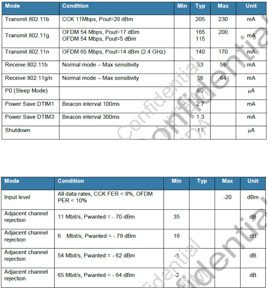
Current Consumption
VBATT = 3.6 volts.
Receiver Performance
VBAT = 3.6 V, Tamb = 25°C.
I/O Characteristics
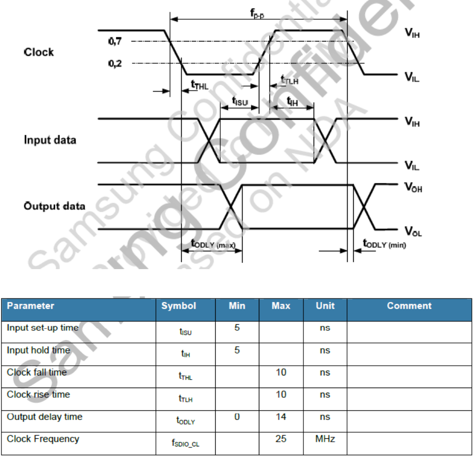
SPI timing characteristics
SPI interface waveforms and timing are below:
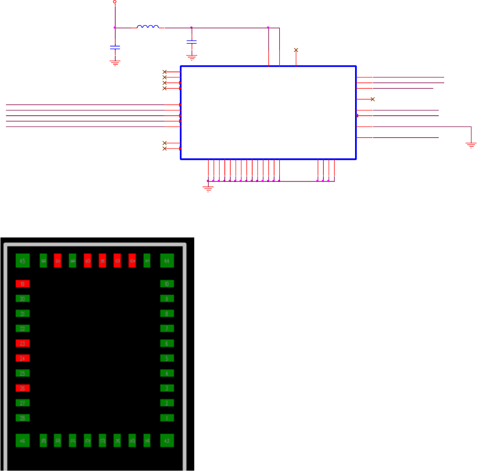
Reference Use Schematic
Module Pinout
Bottom View
ICE_TDI
ICE_TDO
WLAN_SPI_CLK
WLAN_SPI_EN/
WLAN_SPI_DIN
WLAN_SPI_DOUT
WLAN_SPI_IRQ
FB1
BLM15PD121SN1D
U6
GND
1
RESERVED_1 2
NC 3
RESERVED_2 4
WL_EN2
5
WL_RS232_TX 6
WL_EN1
7
WL_RS232_RX 8
GND
9
GND
10
GND
11
GND
16
SPI_IRQ
14
VBAT_IN 19
GND
18
SPI_DIN
15
SPI_CLK
17
SPI_CS
12
SPI_DOUT
13
GND
20
RESERVED_3 24
GND
25
VBAT_SW_EN 26
GND
34
ANT 35
GND
43
GND
44
GND
31
SDA_EEPROM
27
SDA_CC3000
28
SCL_EEPROM
29
SCL_CC3000
30
GND
32
GND
33
GND
36
GND
46 GND
45
VIO_HOST 23
GND
22
EXT_32K 21
C27
6pF
C28
6pF
WLAN_VBAT
WLAN_S_EN
ICE_TMS
ICE_TCK
ON
WLAN Firmware
The firmware is executed from on-chip ROM. Firmware patches are downloaded from host at Power on
Reset, or loaded into RAM from a serial Flash Memory connected to the SPI interface. The firmware
implements the full IEEE 802.11b/g/n wireless LAN MAC protocol, an embedded IP stack together with a
few commonly used applications that can be easily configured and controlled via the chip interface.
The wireless LAN MAC stack supports basic service set (BSS), Mobile AP and WiFi Direct. Low-level
protocol functions such as RTS/CTS, acknowledgement, fragmentation, defragmentation, frame
encapsulation (802.11h/RFC1042) and automatic beacon monitoring / scanning are handled by the
baseband MAC. The IP stack supports TCP, UDP, RTP, and ICMP over IPv4. On top of the IP stack there is
web server with support for Server-Side Includes (SSI) and Common Gateway Interface (CGI) available.
The web pages can be customized via the serial interface.
4.7.1 Features
• 802.11 b/g/n/d/e/i/support
• Infrastructure mode support
• Supports WiFi Direct
• Supports Mobile AP and Mobile router functionality (Soft AP mode) supporting WPS2/WPA2
• IPv4 stack with TCP, UDP and ICMP support
• Web server with Server-Side Includes (SSI) and Common Gateway Interface (CGI)
• Zero config support through support of the mDNS protocol
• Hardware accelerators (software managed hardware) for CCM (CBC-MAC, Counter Mode), TKIP (MIC,
RC4), WAPI (SMS4) and WEP (RC4) along with CRC.
• Supports WPA/WPA2, PSK and Enterprise
• Supports WPS 2.0
• Supports 802.11n up to MCS6 (Tx/Rx). Supporting block ACK, MIMO 1x1 & 2X1, STBC, A-MPDU
aggregation and 0.4us guard interval.
• WMM Power Save U-APSD
• Multiple queue management to fully utilize traffic prioritization defined by the 802.11e standard.
• 802.1h/RFC1042 Frame encapsulation.
• Scattered DMA for optimal CPU off load on Zero Copy data transfers operations.
• Clock/Power gating combined with 802.11-compliant power management dynamically adapted to the
current connection condition providing minimal power consumption.