Skylab M and C Technology
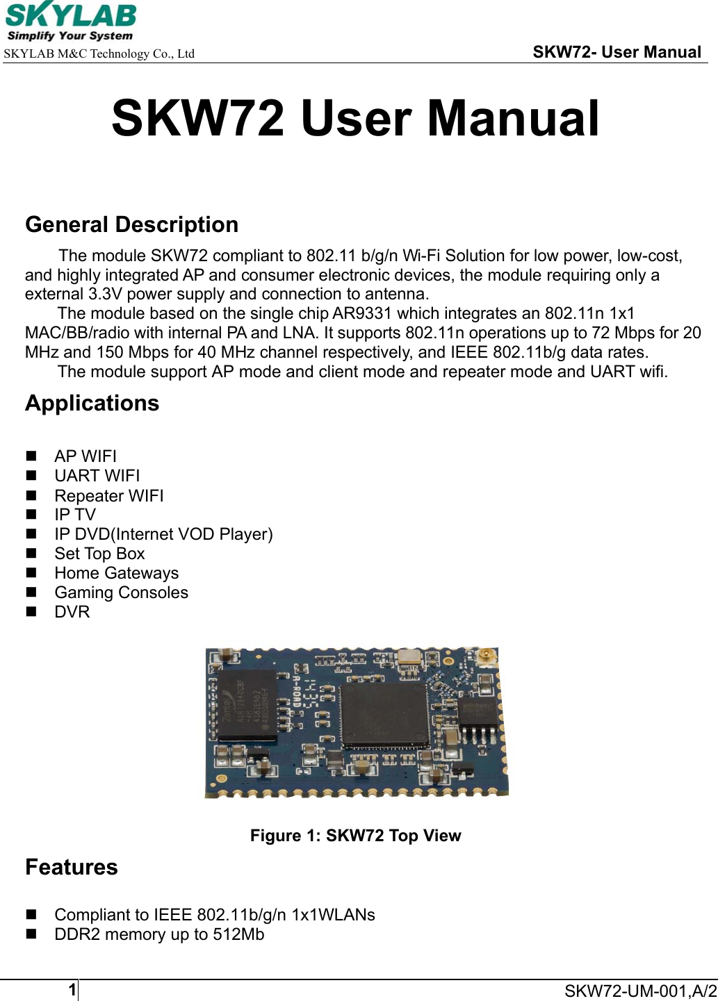
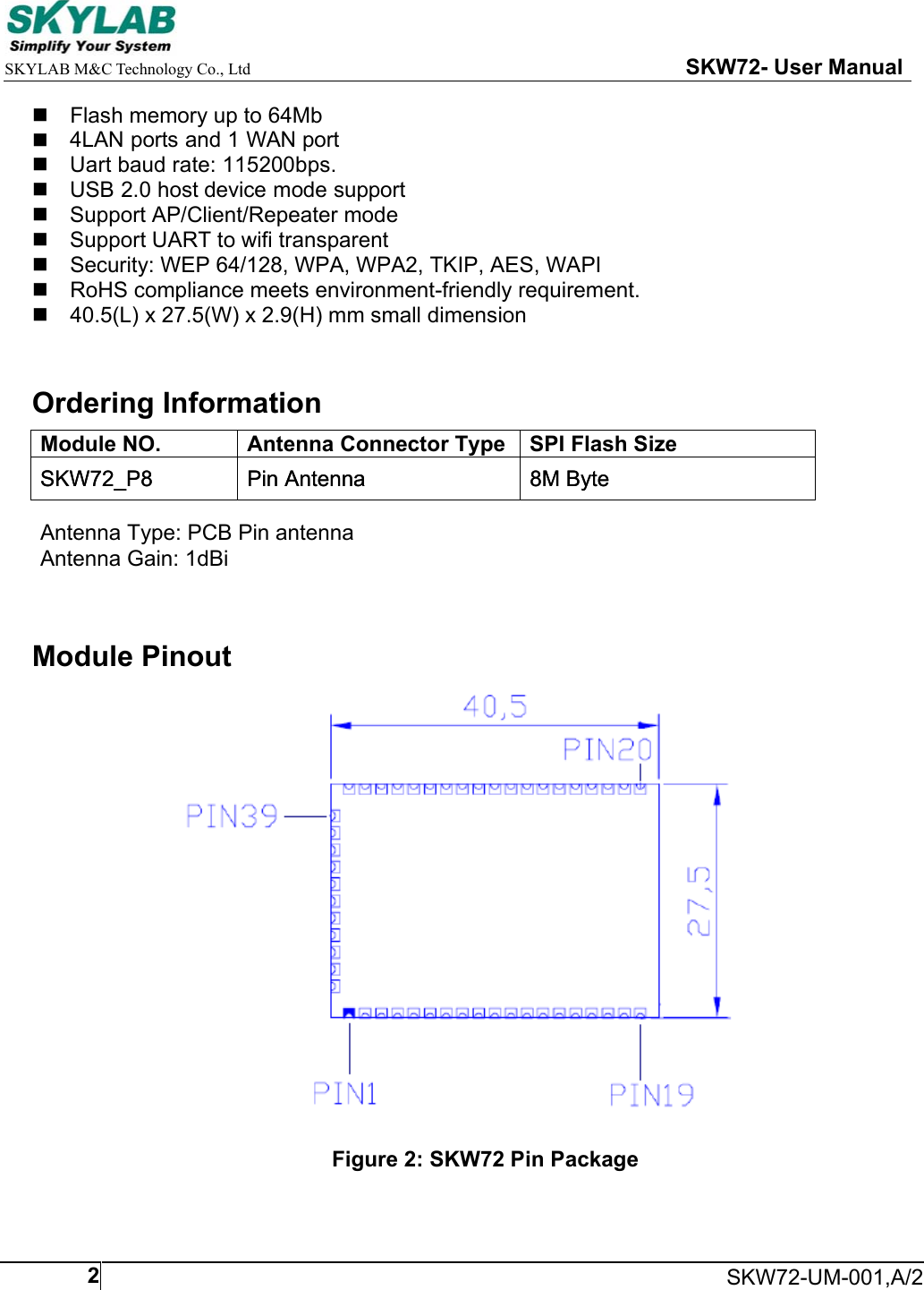
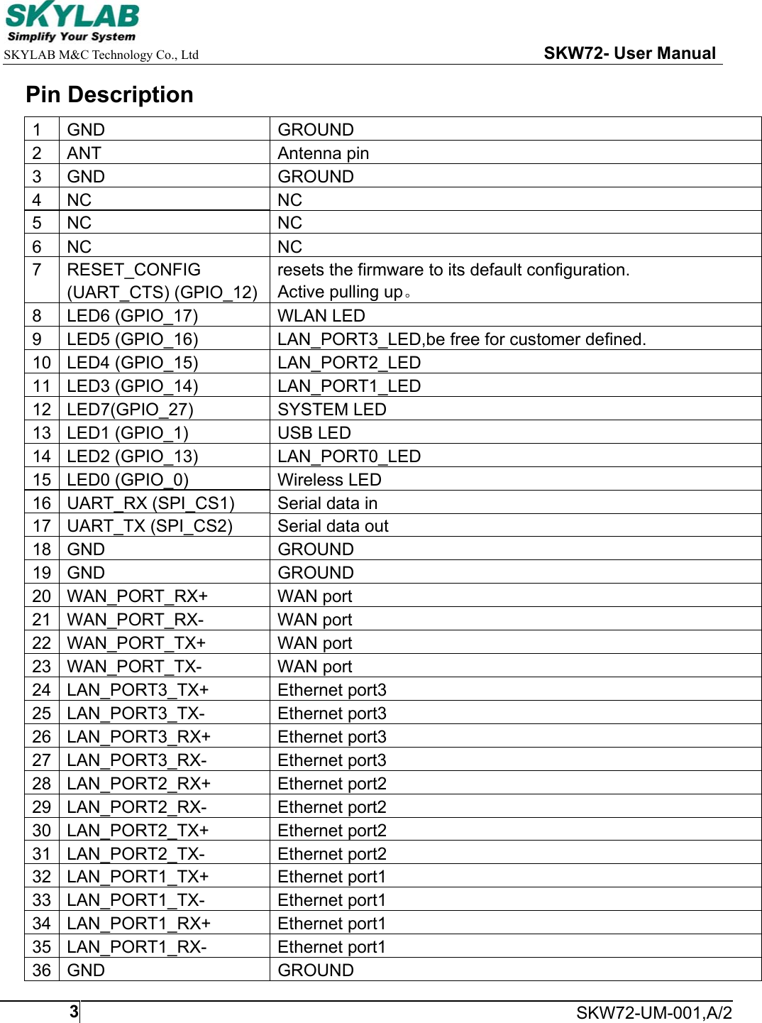
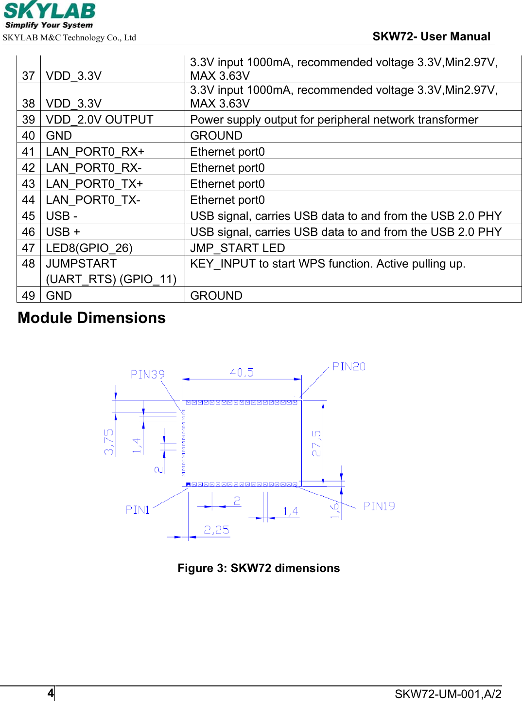
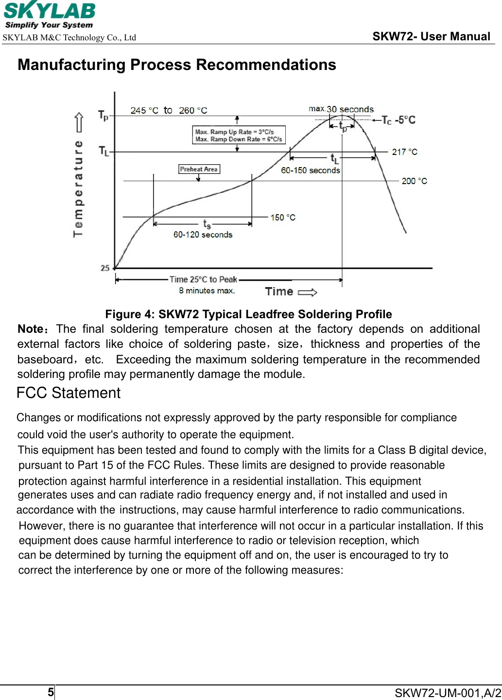
 SKW72 WIFI module User Manual SKW72

Skylab M&C; Technology Co.,Ltd. WIFI module SKW72

User Manual

    SKYLAB M&C Technology Co., Ltd                                                     SKW72- User Manual     SKW72-UM-001,A/21SKW72 User Manual  General Description The module SKW72 compliant to 802.11 b/g/n Wi-Fi Solution for low power, low-cost, and highly integrated AP and consumer electronic devices, the module requiring only a external 3.3V power supply and connection to antenna. The module based on the single chip AR9331 which integrates an 802.11n 1x1 MAC/BB/radio with internal PA and LNA. It supports 802.11n operations up to 72 Mbps for 20 MHz and 150 Mbps for 40 MHz channel respectively, and IEEE 802.11b/g data rates. The module support AP mode and client mode and repeater mode and UART wifi. Applications   AP WIFI  UART WIFI   Repeater WIFI  IP TV   IP DVD(Internet VOD Player)   Set Top Box   Home Gateways   Gaming Consoles  DVR    Figure 1: SKW72 Top View Features   Compliant to IEEE 802.11b/g/n 1x1WLANs   DDR2 memory up to 512Mb
    SKYLAB M&C Technology Co., Ltd                                                     SKW72- User Manual     SKW72-UM-001,A/22  Flash memory up to 64Mb  4LAN ports and 1 WAN port  Uart baud rate: 115200bps.    USB 2.0 host device mode support  Support AP/Client/Repeater mode  Support UART to wifi transparent   Security: WEP 64/128, WPA, WPA2, TKIP, AES, WAPI   RoHS compliance meets environment-friendly requirement.   40.5(L) x 27.5(W) x 2.9(H) mm small dimension  Ordering Information Module NO.  Antenna Connector Type SPI Flash Size SKW72_P8  Pin Antenna  8M Byte Module Pinout             Figure 2: SKW72 Pin PackageSKW72_P8  Pin Antenna  8M Byte Antenna Type: PCB Pin antennaAntenna Gain: 1dBi
    SKYLAB M&C Technology Co., Ltd                                                     SKW72- User Manual     SKW72-UM-001,A/23Pin Description 1  GND  GROUND 2  ANT  Antenna pin 3  GND  GROUND 4  NC  NC 5  NC  NC 6  NC  NC 7  RESET_CONFIG  resets the firmware to its default configuration.    (UART_CTS) (GPIO_12)  Active pulling up。 8  LED6 (GPIO_17)  WLAN LED 9  LED5 (GPIO_16)  LAN_PORT3_LED,be free for customer defined. 10  LED4 (GPIO_15)  LAN_PORT2_LED 11  LED3 (GPIO_14)  LAN_PORT1_LED 12  LED7(GPIO_27)  SYSTEM LED 13  LED1 (GPIO_1)  USB LED 14  LED2 (GPIO_13)  LAN_PORT0_LED 15  LED0 (GPIO_0)  Wireless LED 16  UART_RX (SPI_CS1)  Serial data in 17  UART_TX (SPI_CS2)  Serial data out 18  GND  GROUND 19  GND  GROUND 20  WAN_PORT_RX+  WAN port 21  WAN_PORT_RX-  WAN port 22  WAN_PORT_TX+  WAN port 23  WAN_PORT_TX-  WAN port 24  LAN_PORT3_TX+  Ethernet port3 25  LAN_PORT3_TX-  Ethernet port3 26  LAN_PORT3_RX+  Ethernet port3 27  LAN_PORT3_RX-  Ethernet port3 28  LAN_PORT2_RX+  Ethernet port2 29  LAN_PORT2_RX-  Ethernet port2 30  LAN_PORT2_TX+  Ethernet port2 31  LAN_PORT2_TX-  Ethernet port2 32  LAN_PORT1_TX+  Ethernet port1 33  LAN_PORT1_TX-  Ethernet port1 34  LAN_PORT1_RX+  Ethernet port1 35  LAN_PORT1_RX-  Ethernet port1 36  GND  GROUND
    SKYLAB M&C Technology Co., Ltd                                                     SKW72- User Manual     SKW72-UM-001,A/2437  VDD_3.3V 3.3V input 1000mA, recommended voltage 3.3V,Min2.97V, MAX 3.63V 38  VDD_3.3V 3.3V input 1000mA, recommended voltage 3.3V,Min2.97V, MAX 3.63V 39  VDD_2.0V OUTPUT  Power supply output for peripheral network transformer 40  GND  GROUND 41  LAN_PORT0_RX+  Ethernet port0 42  LAN_PORT0_RX-  Ethernet port0 43  LAN_PORT0_TX+  Ethernet port0 44  LAN_PORT0_TX-  Ethernet port0 45  USB -  USB signal, carries USB data to and from the USB 2.0 PHY 46  USB +  USB signal, carries USB data to and from the USB 2.0 PHY 47  LED8(GPIO_26)  JMP_START LED 48  JUMPSTART  KEY_INPUT to start WPS function. Active pulling up.     (UART_RTS) (GPIO_11) 49  GND  GROUND Module Dimensions  Figure 3: SKW72 dimensions
    SKYLAB M&C Technology Co., Ltd                                                     SKW72- User Manual     SKW72-UM-001,A/25Manufacturing Process Recommendations  Figure 4: SKW72 Typical Leadfree Soldering Profile Note:The  final  soldering  temperature  chosen  at  the  factory  depends  on  additional external  factors  like  choice  of  soldering  paste,size,thickness  and  properties  of  the baseboard,etc.    Exceeding the maximum soldering temperature in the recommended soldering profile may permanently damage the module.    FCC StatementChanges or modifications not expressly approved by the party responsible for compliancecould void the user's authority to operate the equipment.This equipment has been tested and found to comply with the limits for a Class B digital device,pursuant to Part 15 of the FCC Rules. These limits are designed to provide reasonable  protection against harmful interference in a residential installation. This equipment generates uses and can radiate radio frequency energy and, if not installed and used inaccordance with the instructions, may cause harmful interference to radio communications. However, there is no guarantee that interference will not occur in a particular installation. If thisequipment does cause harmful interference to radio or television reception, whichcan be determined by turning the equipment off and on, the user is encouraged to try tocorrect the interference by one or more of the following measures:
Manufacturer:Skylab M&C Technology Co.,Ltd., Hereby ,kylab M&C Technology Co.,Ltd.hereby     SKYLAB M&C Technology Co., Ltd                                                     SKW72- User Manual    SKW72-UM-001,A/26-- Reorient or relocate the receiving antenna.-- Increase the separation between the equipment and receiver.-- Connect the equipment into an outlet on a circuit different from that to which the -- Consult the dealer or an experienced radio/TV technician for helpreceiver is connected.This device complies with part 15 of the FCC rules. Operation is subject to the following two conditions (1)this device may not cause harmful interference, and (2) this device must  accept any interference received, including interference that may cause undesired operationdeclares that this WIFI module, SKW72 is in compliance with the essential requirements and other  relevant provisions of Directive 1999/5/EC.CE StatementThis device complies with part 15 of the FCC rules. Operation is subject to the following twoconditions (1)this device may not cause harmful interference, and (2) this device mustaccept any interference received, including interference that may cause undesired operationFCC Radiation Exposure StatementThe modular can be installed or integrated in mobile or fix devices only.This modular cannot be installed in any portable device, for example,USB dongle like transmitters is forbidden.This modular complies with FCC RF radiation exposure limits set forthfor an uncontrolled environment. This transmitter must not be co?locatedor operating in conjunction with any other antenna or transmitter.This modular must be installed and operated with a minimum distance of 20cm between the radiator and user body.If the FCC identification number is not visible when the moduleis installed inside another device, then the outside of the device into which themodule is installed must also display a label referring to the enclosed module.This exterior label can use wording such as the following:“Contains Transmitter Module FCC ID:2ACOE-SKW72 Or Contains FCC ID:2ACOE-SKW72”when the module is installed inside another device, the user manual of this device must contain below warning statements;1. This device complies with Part 15 of the FCC Rules. Operation is subject tothe following two conditions:(1) This device may not cause harmful interference.(2) This device must accept any interference received, including interferencethat may cause undesired operation.2. Changes or modifications not expressly approved by the party responsiblefor compliance could void the user's authority to operate theequipment.The devices must be installed and used in strict accordance with themanufacturer's instructions as described in the user documentation that comes with the product

Navigation menu