Skylab M and C Technology SKW92 WiFi Module User Manual SKW92
Skylab M&C; Technology Co.,Ltd. WiFi Module SKW92
user manual
Skylab M&C Technology Co., Ltd. SKW92-User Manual
SKW92-UM-001,A/1
1
SKW92 User Manual
General Description
The module SKW92 compliant to 802.11 b/g/n Wi-Fi Solution for low power,
low-cost, and highly integrated AP and consumer electronic devices, the module
requiring only a external 3.3V power supply .
The module based on the single chip MT7628NNwhich integrates an 802.11n
MAC/BB/radio with internal PA and LNA. It supports 802.11n operations up to 144
Mbps for 20 MHz and 300 Mbps for 40 MHz channel respectively, and IEEE
802.11b/g data rates.
The SKW92 module includes an 802.11n MAC and baseband, a 2.4GH z radio and FEM, a
580MHz MIPS CPU, a 5-port 10/100 fast Ethernet switch. Solution for low power, low-cost, and
consumer electronic devices, the module requires only an external 3.3V power supply. It supports
802.11n operating up to 144 Mbps for 20 MHz and 300 Mbps for 40 MHz channel respectively, and
IEEE 802.11b/g data rates.
The module supports bridge mode and AP Client mode and Gateway mode. The high performance
Module can process advanced applications effortlessly, such as security and VoIP. It also includes a
selection of interface to support a variety of applications, such as a USB port for accessing external
storage and 3G/TLE modem. Especially in the IOT, a wide range of applications.
Applications
IP TV
IP DVD(Internet VOD Player)
Set Top Box
Home Gateways
Gaming Consoles
DVR
SKW92-UM-001,A/1
2
Skylab M&C Technology Co., Ltd. SKW92-User Manual
Features
Compliant to IEEE 802.11b/g/n WLANs
2T2R Mode with support for a 300Mbps TX/RX PHY rate.
DDR2 memory up to 512Mb
Flash memory up to 64Mb
4LAN ports and 1WAN port
Support USB 2.0 host device
Support USB disk.
Security: WEP 64/128, WPA, WPA2, TKIP, AES, WAPI
RoHS compliance meets environment-friendly requirement.
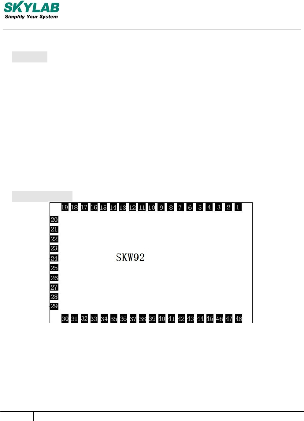
Module Pinout
Figure 1: SKW92 Pin Name
SKW92-UM-001,A/1
3
Skylab M&C Technology Co., Ltd. SKW92-User Manual
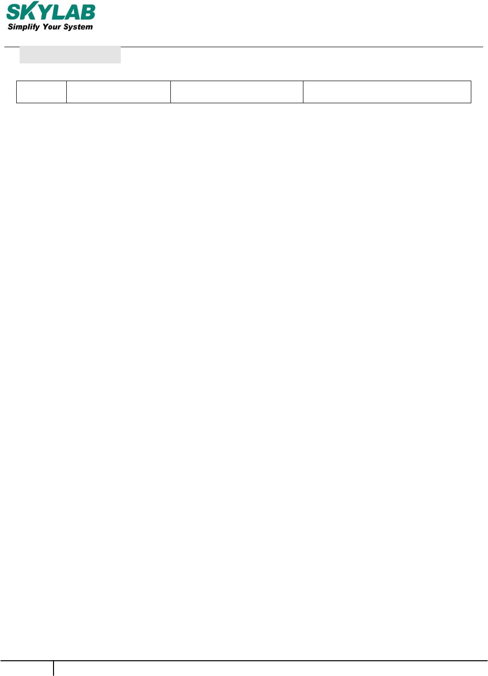
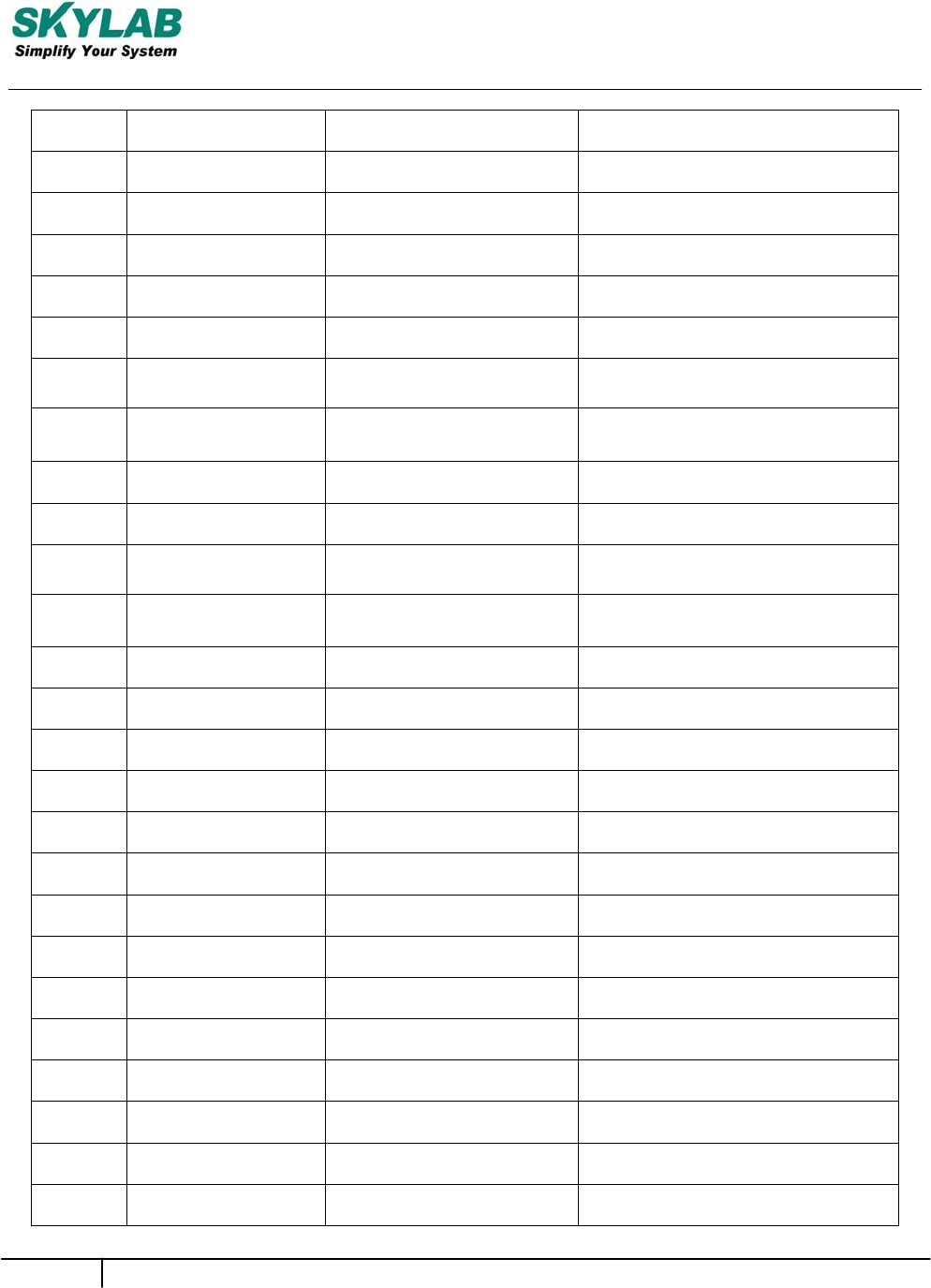
Pin Description
Pin No. Pin name Description Remark
SKW92-UM-001,A/1
4
Skylab M&C Technology Co., Ltd. SKW92-User Manual
1
WAN_PORT_RX+ WAN port WAN_RX+
2
WAN_PORT_RX- WAN port WAN_RX-
3
WAN_PORT_TX+ WAN port WAN_TX+
4
WAN_PORT_TX- WAN port WAN_TX-
5
LAN_PORT1_TX+ Ethernet port1 SPIS_CS / GPIO#14 / PWM0
6
LAN_PORT1_TX- Ethernet port1 SPIS_CLK / GPIO#15 / PWM1
7
LAN_PORT1_RX+ Ethernet port1 SPIS_MISO / GPIO#16 /
UART2 TXD
8
LAN_PORT1_RX- Ethernet port1 SPIS_MOSI / GPIO#17 /
UART2 RXD
9
LAN_PORT2_RX+ Ethernet port2 GPIO#18 / PWM0 / SD_D7
10 LAN_PORT2_RX- Ethernet port2 GPIO#19 / PWM1 / SD_D6
11 LAN_PORT2_TX+ Ethernet port2 GPIO#20 / PWM2 /
UART2 TXD / SD D5
12 LAN_PORT2_TX- Ethernet port2 GPIO#21 / PWM3 /
UART2 RXD / SD D4
13 LAN_PORT3_TX+ Ethernet port3 SD_WP / GPIO#22
14 LAN_PORT3_TX- Ethernet port3 SD_CD / GPIO#23
15 LAN_PORT3_RX+ Ethernet port3 SD_D1 / GPIO#24
16 LAN_PORT3_RX- Ethernet port3 SD_D0 / GPIO#25
17 GND Ground GND
18 USB+ USB data pin Data+ USB_D+
19 USB- USB data pin Data- USB_D-
20 GND Ground GND
21 LAN_PORT4_RX+ Ethernet port4 SD_CLK / GPIO#26
22 LAN_PORT4_RX- Ethernet port4 SD_CMD/ GPIO#27
23 LAN_PORT4_TX+ Ethernet port4 SD_D3 / GPIO#28
24 LAN_PORT4_TX- Ethernet port4 SD_D2 / GPIO#29
25 UART_RXD0 UART0 only for debug UART0_RX / GPIO#13
26 UART_TXD0 UART0 only for debug UART0_TX / GPIO#12 / O, IPD
SKW92-UM-001,A/1
5
Skylab M&C Technology Co., Ltd. SKW92-User Manual
27 GND Ground GND
SKW92-UM-001,A/1
6
Skylab M&C Technology Co., Ltd. SKW92-User Manual
28 3.3VD 3.3V input 1000mA +3.3V
29 3.3VD 3.3V input 1000mA +3.3V
30 GND Ground GND
31 P4_LED LAN_PORT4_LED P4_LED_N / GPIO#39
32 P3_LED LAN_PORT3_LED P3_LED_N / GPIO#40
33 P2_LED LAN_PORT2_LED P2_LED_N /GPIO#41
34 P1_LED LAN_PORT1_LED P1_LED_N/ GPIO#42
35 P0_LED WAN_PORT_LED P0_LED_N / GPIO#43
36 WLED_N Wireless LED WLED_N / GPIO#44
37
UART_TXD1 UART1 Serial Data
Output UART1_TXD / GPIO#45 / O,
IPU
38
UART_RXD1
UART 1 Serial Data Input
UART1_RXD / GPIO#46
39
WDT_RST_N WPS/Factory
Setting_Button_Key WDT_RST_N /I2S_MCLK /
GPIO#38/O, IPU
40 WPS_LED WPS_LED WPS_LED_N / GPIO#37
41 I2S_DI I2S data input I2S_SDI/GPIO#0/PCMDRX
42 I2S_WS I2S word select I2S_WS/GPIO#2/PCMCLK
43
I2S_DO
I2S data output I2S_SDO
/GPIO#1/PCMDTX/IPD
44 I2S_CLK I2S clock I2S_CLK/GPIO#3/PCMFS
45 HW_RESET Power on reset HW_RESET_N#
46 I2C_SD I2C Data I2C_SDA(PU 2K2) / GPIO#5
47 I2C_SCLK I2C clock I2C_SCL(PU 2K2) / GPIO#4
48 GPIO0 General Purpose I/O POWER_ON# / GPIO#11/IPD
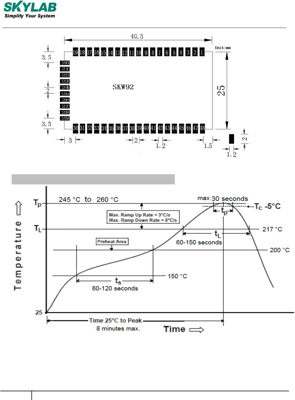
PCB Dimensions
SKW92-UM-001,A/1
7
Skylab M&C Technology Co., Ltd. SKW92-User Manual
Figure 2: SKW92 Dimensions
Manufacturing Process Recommendations
Figure 3: SKW92Typical Lead-free Soldering Profile
Note:The final soldering temperature chosen at the factory depends on additional external factors like choice
of soldering paste,size,thickness and properties of the baseboard,etc. Exceeding the maximum soldering
temperature in the recommended soldering profile may permanently damage the module.

SKW92-UM-001,A/1
8
Skylab M&C Technology Co., Ltd. SKW92-User Manual
Ordering Information
Module No. Antenna Connector Type SPI Flash Size
SKW92-UM-001,A/1
9
Skylab M&C Technology Co., Ltd. SKW92-User Manual
SKW92_8
IPEXConnector
8MBytes
SKW92_16
IPEXConnector 16MBytes

Skylab M&C Technology Co., Ltd. SKW92-User Manual
FCC Statement
Changes or modifications not expressly approved by the party responsible for compliance
could void the user's authority to operate the equipment.
This equipment has been tested and found to comply with the limits for a Class B digital device,
pursuant to Part 15 of the FCC Rules. These limits are designed to provide reasonable
protection against harmful interference in a residential installation. This equipment
generates uses and can radiate radio frequency energy and, if not installed and used in
accordance with the instructions, may cause harmful interference to radio communications.
However, there is no guarantee that interference will not occur in a particular installation. If this
equipment does cause harmful interference to radio or television reception, which
can be determined by turning the equipment off and on, the user is encouraged to try to
correct the interference by one or more of the following measures:
-- Reorient or relocate the receiving antenna.
-- Increase the separation between the equipment and receiver.
-- Connect the equipment into an outlet on a circuit different from that to which the
-- Consult the dealer or an experienced radio/TV technician for help
receiver is connected.
This device complies with part 15 of the FCC rules. Operation is subject to the following two
conditions (1)this device may not cause harmful interference, and (2) this device must
accept any interference received, including interference that may cause undesired operation
FCC Caution: Any changes or modification not expressly approved by the party responsible for
compliance could void the user’s authority to operate.
This equipment complies with FCC radiation exposure limits set forth for an uncontrolled
environment.
7
SKW92-UM-001,A/1
8 SKW92-UM-001,A/1
SKYLAB M&C Technology Co., Ltd SKW92-User Manual
Skylab M&C Technology Co., Ltd.
FCC Radiation Exposure Statement
The modular can be installed or integrated in mobile or fix devices only. This modular cannot
be installed in any portable device, for example, USB dongle like transmitters is forbidden.
This modular complies with FCC RF radiation exposure limits set forth for an uncontrolled
environment. This transmitter must not be collocated or operating in conjunction with any other
antenna or transmitter.
If the FCC identification number is not visible when the module is installed inside another
device, then the outside of the device into which the module is installed must also display a
label referring to the enclosed module.
This exterior label can use wording such as the following:
“Contains Transmitter Module FCC ID:2ACOE-SKW92 Or Contains FCC ID:2ACOE-SKW92''
when the module is installed inside another device, the user manual of this device must
contain below warning statements;
1. This device complies with Part 15 of the FCC Rules. Operation is subject to the following
two conditions:
(1) This device may not cause harmful interference.
(2) This device must accept any interference received, including interference that may cause
undesired operation.
2. Changes or modifications not expressly approved by the party responsible for compliance
could void the user's authority to operate the equipment.
The devices must be installed and used in strict accordance with the manufacturer's
instructions as described in the user documentation that comes with the product.
3. Integrator is responsible for final compliance of the end-product
> > that integrates this modular transmitter.
> > 15B Compliance on final product with integrated modular transmitter
> > 15C Evaluation of RF Parameter of the modular transmitter (e.g.
> > Fundamental, Out-of-Band Emissions)
4. Integration strictly limited to host platform (Wireless Router and similar devices)
5. This module is not shielding.

8 SKW92-UM-001,A/1
SKYLAB M&C Technology Co., Ltd SKW92-User Manual
Skylab M&C Technology Co., Ltd.
ThisdeviceisintendedonlyforOEMintegratorsunderthefollowing
conditions:
1) Theantennamustbeinstalledsuchthat20cmismaintainedbetweentheantenna
andusersc.
2) Thetransmittermodulemaynotbeco‐locatedwithanyothertransmitteror
antenna.
3) ForallproductsmarketinUnitedStates,OEMhastolimittheoperationchannelsinCH1
toCH11for2.4Gbandbysuppliedfirmwareprogrammingtool.AndOEMshall
notsupplyanytoolorinfototheend‐userregardingtochangethedomainselection.
Aslongas3conditionsabovearemet,furthertransmittertestwillnotberequired.
However,theOEMintegratorisstillresponsiblefortestingtheirend‐productfor
anyadditionalcompliancerequirementsrequiredwiththismoduleinstalled(for
example,digitaldeviceemissions,PCperipheralrequirements,etc.).
IMPORTANTNOTE:Intheeventthattheseconditionscannotbemet(for
examplecertainlaptopconfigurationsorco‐locationwithanothertransmitter),then
theFCCauthorizationisnolongerconsideredvalidandtheFCCIDcannotbe
usedonthefinalproduct.Inthesecircumstances,theOEMintegratorwillbe
responsibleforre‐evaluatingtheendproduct(includingthetransmitter)and
obtainingaseparateFCCauthorization.
EndProductLabeling
Thistransmittermoduleisauthorizedonlyforuseindevicewheretheantennamay
beinstalledsuchthat20cmmaybemaintainedbetweentheantennaandusers
Thefinalendproductmustbelabeledinavisibleareawiththefollowing:“ContainsFCCID:
2ACOE‐SKW92”.
ModuleAntennaType:PCBPINANT,1.5dBigain