Skyline Partners Technology Fastback Networks 101 Intelligent Backhaul Radio ISM 5.8GHz band User Manual OEM Volume Ag Bass
CBF Networks, Inc., dba Fastback Networks Intelligent Backhaul Radio ISM 5.8GHz band OEM Volume Ag Bass
Contents
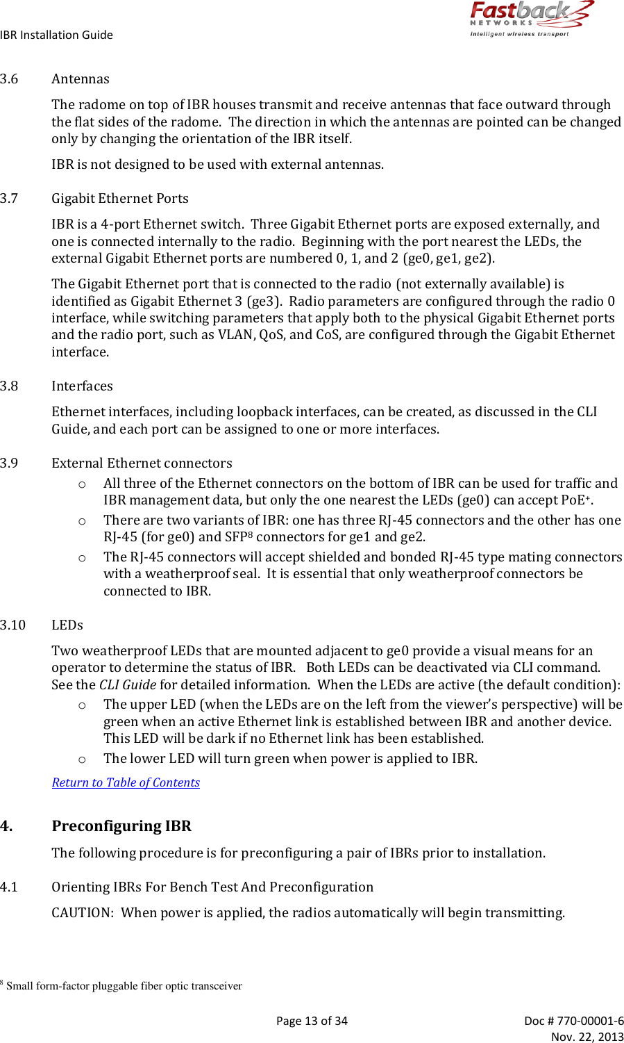
- 1. Install Guide
- 2. Installation manual
Install Guide

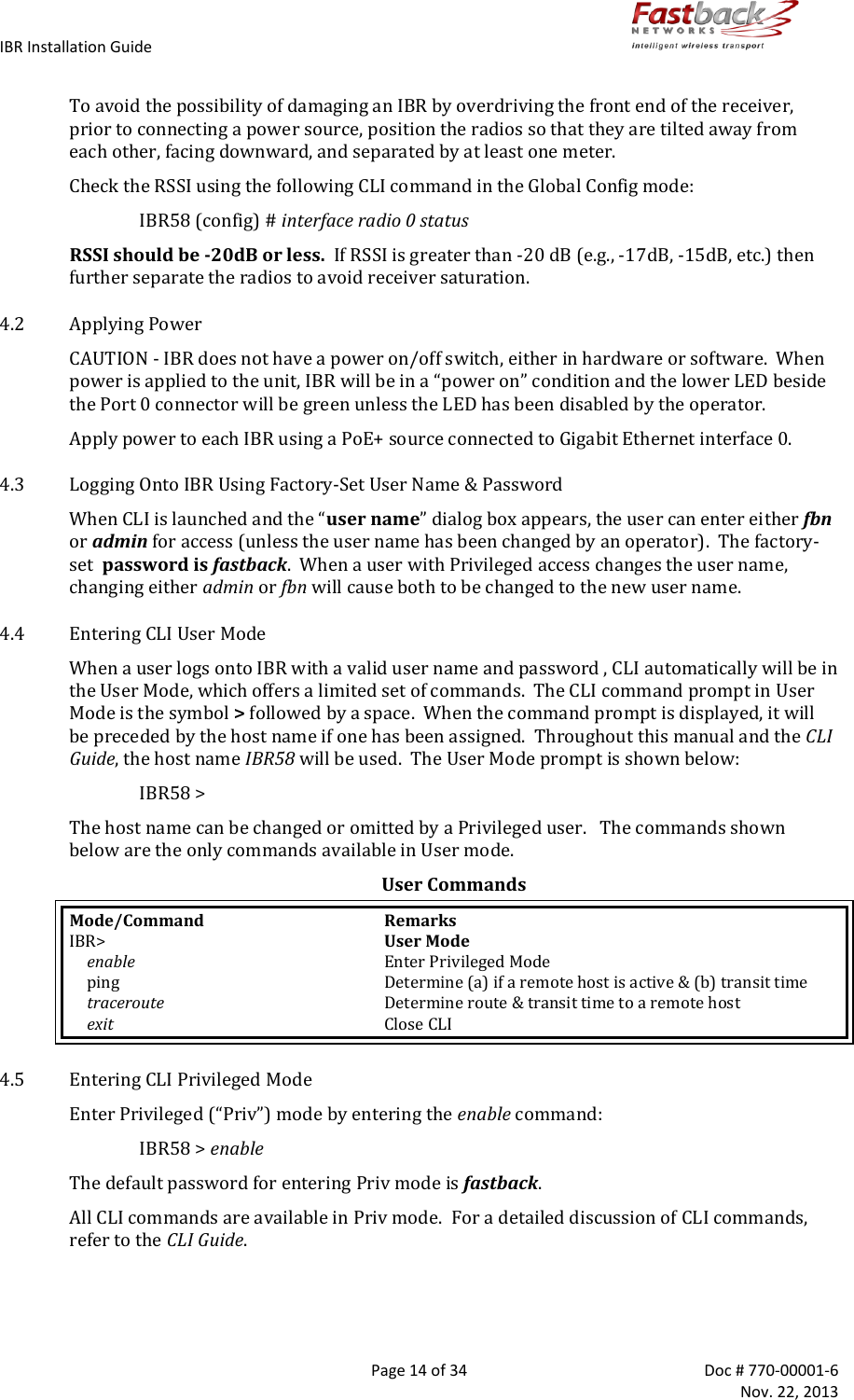
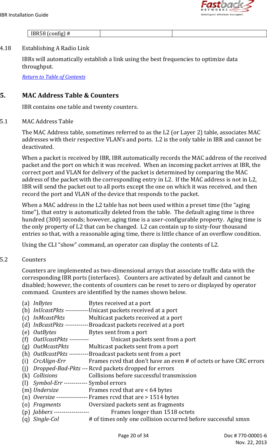
![IBR Installation Guide Page 18 of 34 Doc # 770-00001-6 Nov. 22, 2013 One use of this interface is to allow a user to send ping packets to the opposite IBR to verify link integrity. This VLAN has no exposure to a physical network interface so traffic on this VLAN is isolated from the network. 4.9 Saving New Configuration Use the following commands to save the new settings to the startup configuration file. IBR58 (config)# copy running-config start-up config 4.10 Changing Host Name Change the host name using the following command in Global Config mode. IBR58 (config) # host name [newname] 4.11 Changing Passwords The command for setting or changing a password has the following form: IBR58 # enable password {level (1, 15)} [newpassword] where “level” must either be the number 1 or the number 15 and newpassword must be a string of at least six and not more than sixteen characters and can include any letter, any numeral, and any of the following symbols: ! @ # $ % . o When level = 1, the password to enter User Mode will be affected. o When level = 15, the password to enter Privileged Mode will be affected. When no level option is entered, Privileged Mode will be affected. 4.12 Password Recovery In the event that the Privileged Mode password is forgotten, the following procedure can be used to reset all IBR settings to their default values, thereby allowing a user to regain access to IBR. This procedure will boot IBR into a Linux root shell single-user mode where the user can change the Privileged Mode password. o Initiate a system reboot and, within two (2) seconds, press Ctrl C to interrupt the reboot process. Enter the following command when the uMON> prompt is displayed: uMON> run flash all o IBR will take several minutes to reboot. When the Linux prompt is displayed, enter the command passwd root and then respond to the succeeding prompts to change the Privileged Mode password and reboot the system. o When IBR reboots to CLI User Mode, use the default user name and password to log onto the system. Use the new Privilege Mode password to enter Privilege Mode. o Then follow the standard procedure to change the User Mode Unser name and password. Note: To interrupt an ongoing reboot, enter the command Ctrl C. 4.13 Setting System Clock The command to set the IBR system clock is executed in Global Config mode and has the following form. IBR58 (config) # clock set [hh:mm:ss] [YYYY-MM-DD] where all of the arguments are integers.](https://usermanual.wiki/Skyline-Partners-Technology-Fastback-Networks/101.Install-Guide/User-Guide-2126733-Page-18.png)
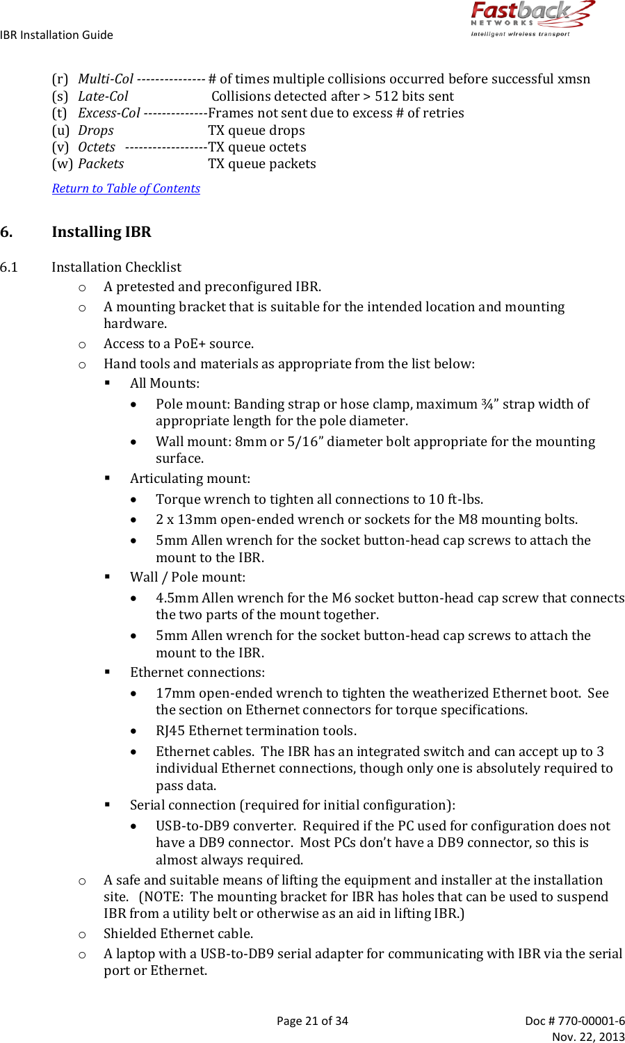
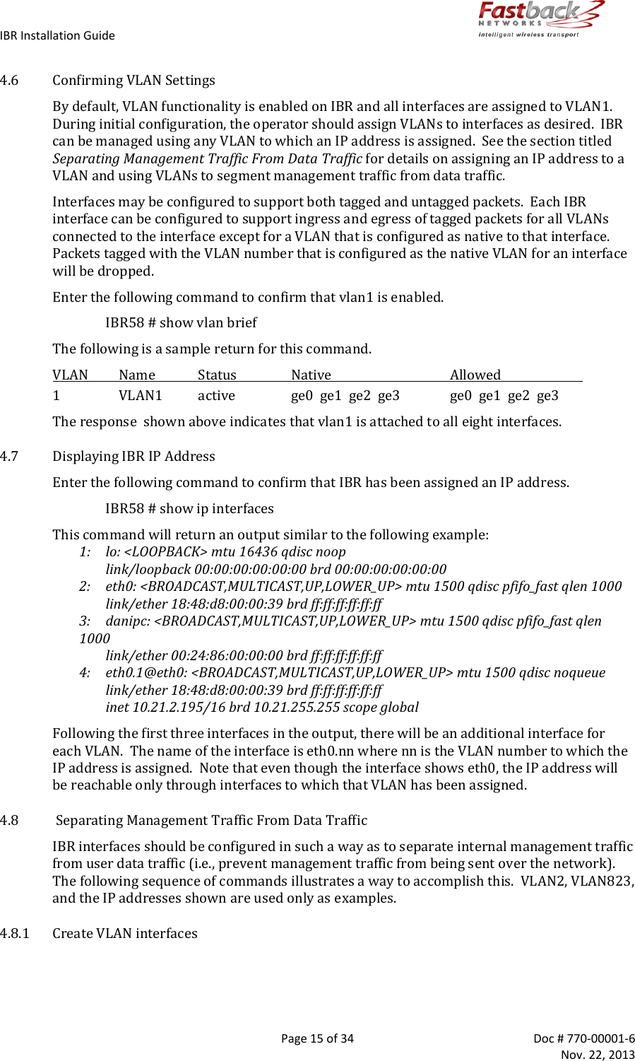
![IBR Installation Guide Page 19 of 34 Doc # 770-00001-6 Nov. 22, 2013 4.14 Configuring IBR Name Server The following command can be used to configure the Name server. IBR58 (config)# ip name-server [ip-address} 4.15 Configuring IBR NTP Server The following command can be used to configure the NTP server. IBR58 (config)# ntp server [ip-address} 4.16 Configuring IBR SNMP Server The following sequence of commands can be used to configure the SNMP server. IBR58 (config) # snmp-server host [ip-address] IBR58 (config) # snmp-server community [com-name] IBR58 (config) # snmp-server group [grp-name] IBR58 (config) # snmp-server view [vname] Examples of configuring an SNMP Server are shown below. Setting up an SNMPv2 Trap Server Prompt Command Remarks IBR58 (config) # snmp-server community fastback rw Use “fastback” or read/write IBR58 (config) # snmp-server host 10.0.0.1 traps version v2c Traps SNMPv2 IBR58 (config) # exit Return to Global Config IBR58 # show snmp-server host Returns Notification Host: 10.21.0.4 udp-port: 162 type: inform user: snmptraps security model: v2c Notice the community string is not returned with the show command Setting up a Default Gateway Prompt Command Remarks IBR58 (config) # ip default-gateway 10.10.0.1 Config radio interface “0” IBR58 (config) # exit Return to Global Config IBR58 # show ip route Returns 10.10.0.0/16 dev eth0.53 src 10.1.1.10 default via 10.10.0.1 dev eth0.1 Default gateway using VLAN 1 4.17 Setting Link ID The command to set Link ID has the following syntax: IBR58 (config) # link-id [linkname] where linkname is an alphanumeric string from one to thirty-two characters in length that can contain any of the following symbols: ! @ # $ % - _ Using Link ID Command Prompt Command Remarks IBR58 (config) # interface radio 0 Config radio interface “0” IBR58 (config-if-rad0) # link-id 58$a2 Sets link ID to “58$a2” IBR58 (config-if-rad0) # exit Return to Global Config](https://usermanual.wiki/Skyline-Partners-Technology-Fastback-Networks/101.Install-Guide/User-Guide-2126733-Page-19.png)