Skytech II TS-R-2A Fireplace Remote Control User Manual TS R 2 instructions
Skytech II, Inc. Fireplace Remote Control TS R 2 instructions
User Manual
REV 3/3/04
Page 1 of 5
TS/R-2
INSTALLATION AND OPERATING INSTRUCTIONS
INTRODUCTION
SKYTECH’S remote wall mount thermostat system was developed to provide a safe, reliable and user-friendly wireless remote wall mount
thermostat for gas heating appliances. Battery operation allows the system to operate independently of household current. The system
operates on radio frequencies with non-directional signals. The SYSTEMS operating range is approximately 20 feet. The system operates on
one of 255 security codes programmed at the factory.
COMPONENTS
THE SKYTECH TS/R-2 MUST BE INSTALLED EXACTLY
AS OUTLINED IN THESE INSTRUCTIONS. READ
COMPLETELY BEFORE ATTEMPTING INSTALLATION.
FOLLOW INSTRUCTIONS CAREFULLY DURING
INSTALLATION. ANY MODIFICATION OF THE
SKYTECH TS/R-2 OR ANY OF ITS COMPONENTS WILL
VOID THE WARRANTY AND MAY POSE A FIRE
HAZARD.
WALL MOUNT THERMOSTAT
The wall/transmitter operates on (2) 3V Button Cell (Included) which powers the LCD screen. These
batteries are made specifically for remote controls and electronic lighters. Before using the transmitter the
3V batteries must be installed into the battery compartments.
It is recommended that ALKALINE batteries always be used for longer battery life and maximum
operational performance.
Upon initial use, there may be a delay of five seconds before the remote receiver will respond to the
transmitter. This is part of the system’s design. If the LCD screen will not come on, check the 3V Button
Cell battery.
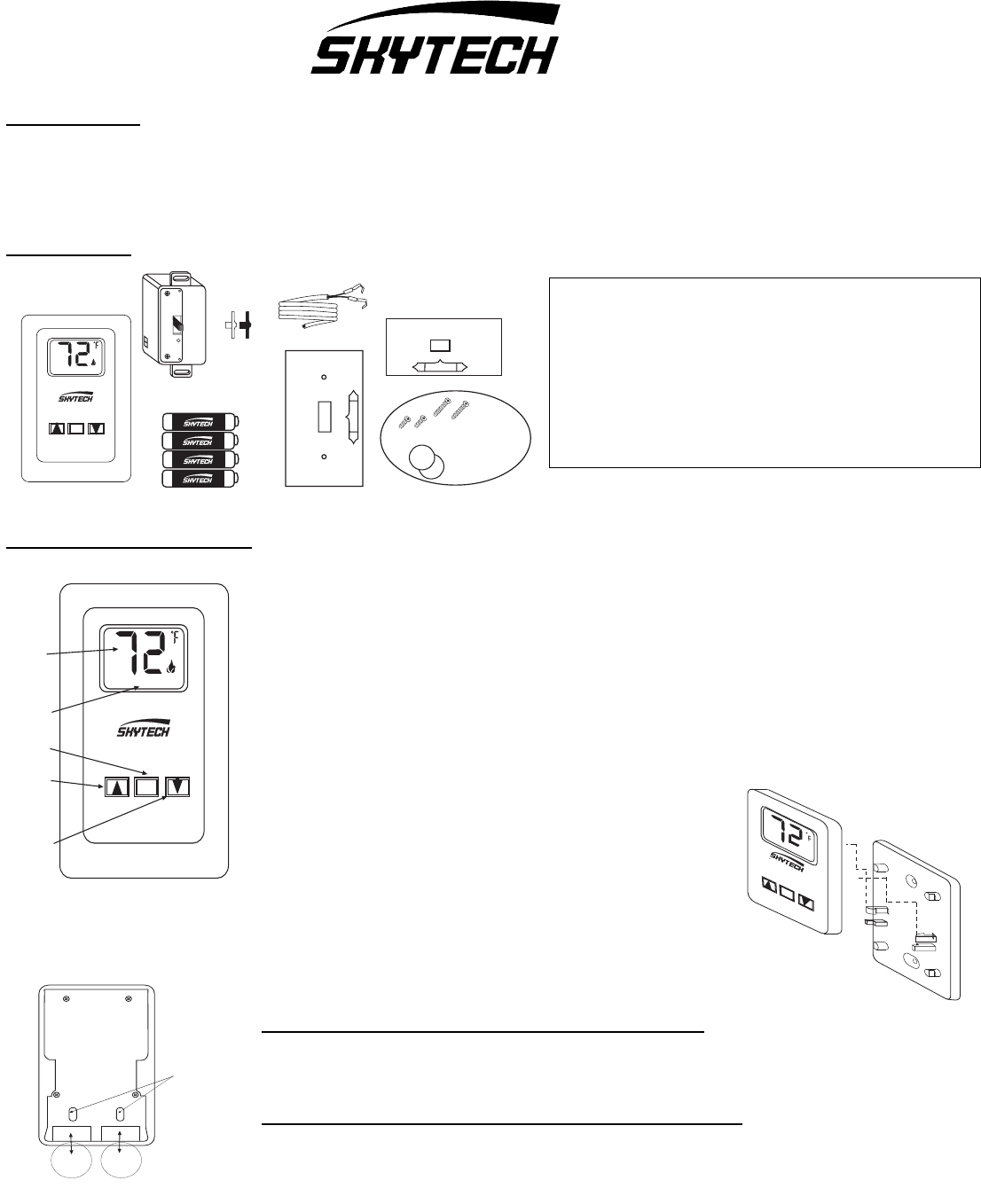
To activate LCD screen install the (2) 3V button cell batteries.
The wall thermostat operates on a (2) 3V button cell
batteries (included) made specifically for remote controls.
Before using the wall thermostat, install the two (2) 3V
button cell batteries. Follow instructions below.
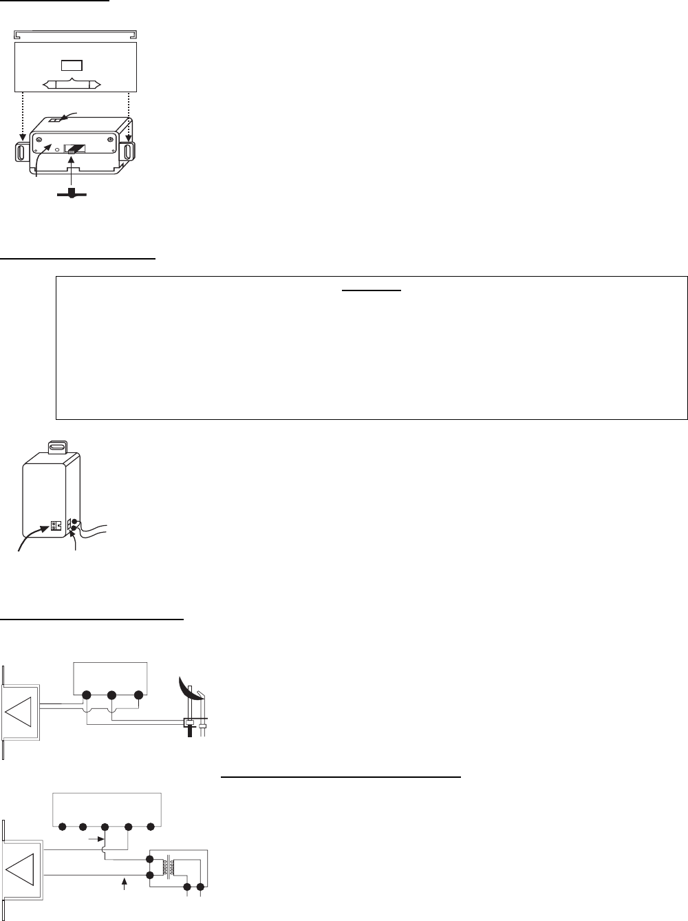
First you must remove the face of the thermostat. This is
Done by sliding the face up about 1/2” then pull the face
off the base plate. As shown at the right.
TO INSTALL BATTERIES IN THE WIRELESS THERMOSTAT
1. Remove face from backing plate and locate the (2) holders for the 3V button cell batteries.
2. Slide the button cell batteries into the battery holders. (Make sure that the batteries
are installed with the (+) plus side facing you).
TO REMOVE THE BATTERIES IN THE WIRELESS THERMOSTAT
1. Remove face from backing plate and locate the (2) holders for the 3V button cell batteries.
2. Insert a small screwdriver into the slot above the button cell battery and push the battery out (Slots
shown in picture to the left).
ROOM TEMP
ON OFF
SET
ROOM TEMP
THERMO
MODE
“SET”
ON
SET
OFF
LCD
DISPLAY
ON/UP
BUTTON
OFF/DOWN
BUTTON
SET
BUTTON
TOP
TRANSMITTER
REMOTE RECEIVER
SLIDE
BUTTONS
REMOTE
ON
OFF
SLIDE-ON COVERPLATE
R
E
M
O
T
E
ON
OFF
2 ea. 12V (A23) Transmitter
battery(included in
transmitter)
4 ea.
WALL-MOUNT COVERPLATE HARDWARE
(2) 3V Button Cell Transmitter
batteries (included in
transmitter)
AA BATTERIES
3V
3V
ROOM TEMP
ON
SET
OFF
SET
WIRING KIT
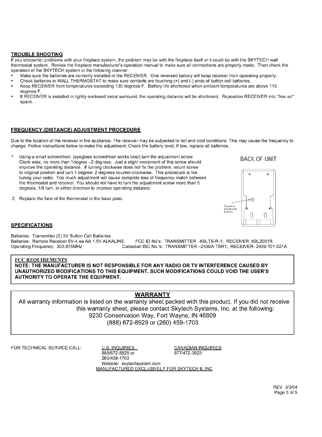
BACK OF UNIT
(2) 3 Volt Button
Cell Batteries
Battery Removal
Slots
+
Plus
Side
+
Plus
Side
REV 3/3/04
Page 2 of 5
TOP
Requires 4-AA 1.5V
alkaline batteries
(not included)
Battery cover slides on/off
Slide
Switch
ON
REMOTE
OFF
WALL
Plastic Switch Box
Remote Receiver
Cover Plate
R
eceiver
Slide
Button
TOP
R
E
M
O
T
E
ON
OFF
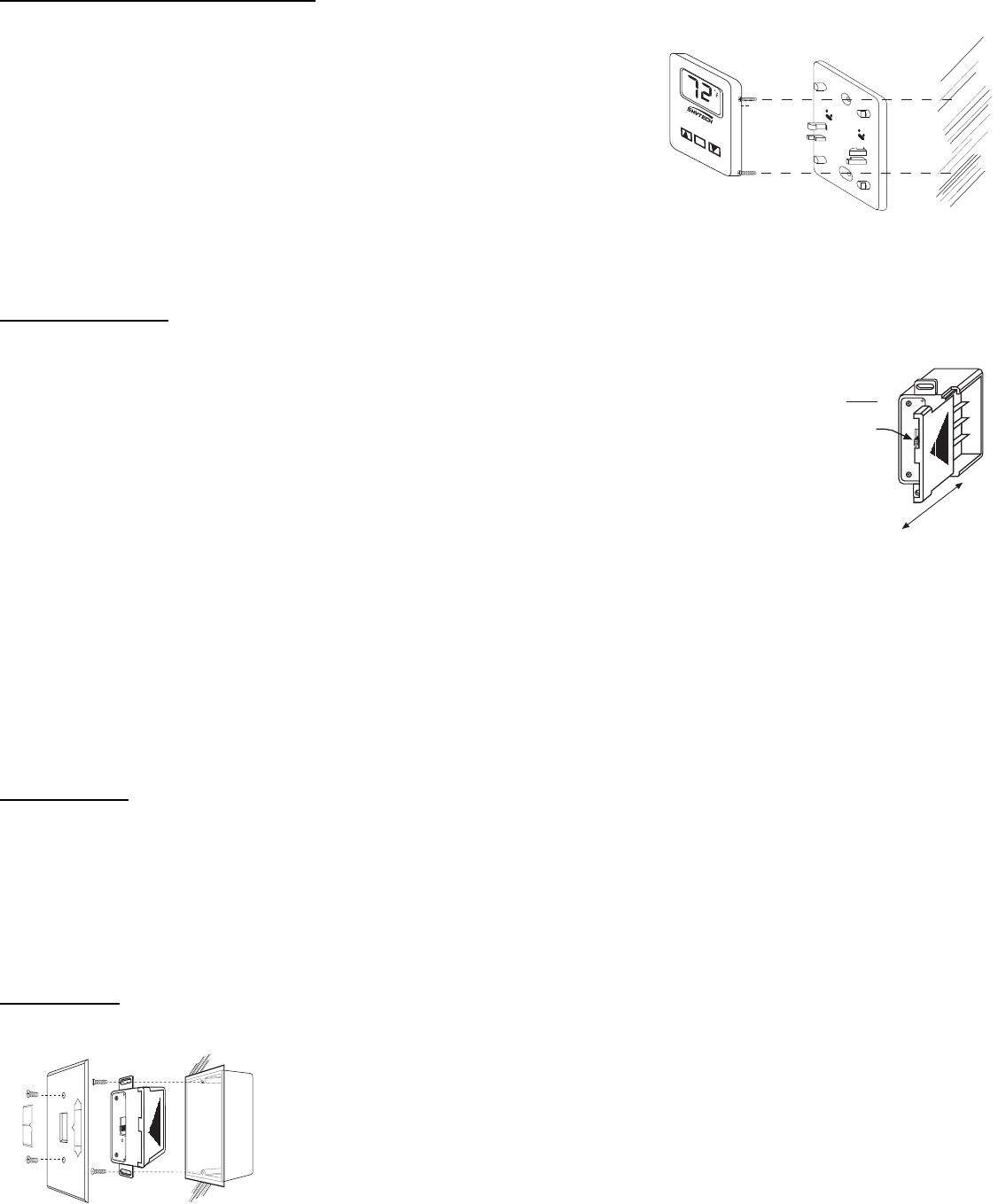
WALL MOUNTING THE THERMOSTAT
1. The wireless Thermostat must be located within 20’ of the receiver, This is proper
operational distance.
2. Remove face from backing plate as shown at the start of these instructions
then locate the (2) two holes that mount the plate to the wall.
3. Locate the (2) two mounting holes and mark the holes on the wall.
4. Use the (2) two dry wall anchors and screws ( that are supplied) to mount
the base plate to the wall as shown.
5. Thermostat can also be mounted onto an existing (Plastic) electrical box.
6. Base plate should be mounted level on the wall for best operation.
REMOTE RECEIVER
IMPORTANT: THE REMOTE RECEIVER SHOULD BE POSITIONED WHERE AMBIENT
TEMPERATURES DO NOT EXCEED 130 DEGREE F.
The remote receiver (right) operates on four 1.5V AA- size batteries (Included). It is recommended that ALKALINE
batteries be used for longer battery life and maximum microprocessor performance. IMPORTANT: New or fully
charged batteries are essential to proper operation of the remote receiver.
NOTE: The remote receiver will only respond to the transmitter when the 3-position slide button on the remote
receiver is in the REMOTE (center) position.
The remote receiver houses the microprocessor that responds to commands from the thermostat to control system
operation. The remote receiver has a 3-position slide switch (see figure at right) for selecting the mode of operation:
ON/REMOTE/OFF.
• With the slide switch in the ON position (toward the word TOP), the system will remain on until the slide switch is placed in the OFF or
REMOTE position. This manual switch will turn ON or OFF the system, without the transmitter or good batteries.
• With the slide switch in the REMOTE position (centered), the system will only operate if the remote receiver receives commands from the
thermostat. Upon initial use or after an extended period of no use the ON button must be pressed for up to five seconds.
• With the slide switch in the OFF position (away from the word TOP), the system is off.
• It is suggested that the slide switch be placed in the OFF position if you will be away from your home for an extended period of
time. If the remote receiver is mounted out of children’s reach, placing the slide switch in the OFF position also functions as a
safety “lock out” by both turning the system off and rendering the thermostat inoperative.
INSTALLATION
NOTE: When the remote receiver is installed as a wall switch, It is recommended that it be installed
in a PLASTIC switch box. Remote functions may not operate properly if the remote
receiver is installed in a steel switch box.
Make sure the remote receiver switch is in the OFF position (toward the small hole on the receiver’s face). It is recommended that 18 gauge,
stranded wires (Included) be used for wire installation between the terminal wiring block on the millivolt gas valve or electronic ignition system
and the wire terminals on the remote receiver. For best results, use 18-gauge wire that has not been spliced and measuring no longer than 20
ft.
WALL MOUNT
Install four 1.5V AA-size ALKALINE batteries (Included) in the remote receiver. For best performance,
remote receiver batteries should be factory fresh when installed. Very little battery power is required to
operate the remote receiver, but the electronics are tuned to operate best when battery output is greater
than 5.3 volts. For new AA batteries should provide an output voltage of 6.0 to 6.2 volts.
Position the remote receiver so the word TOP is facing up, then install the remote receiver into the
plastic switch box using the two long screws provided. Install the cover plate using the two short screws
provided.
Push the remote receiver slide button over the remote receiver slide switch. Reverse installation of the
slide button if it appears off center
WALL
ROOM TEMP
ON OFF
SET
REV 3/3/04
Page 3 of 5
REMOTE
ON
OFF
Slide-on cover plate
TOP
Remote
Receiver
(bottom view of slide-on cover plate)
Face
Plate
Receiver Slide Button (back)
Wire Terminals
Remote
Receiver
2. Tighten screws
to hold wires
1. Insert wires into
wire terminals
ELECTRONIC MODULE
TR TH
REMOTE
RECEIVER
neutral wire
24VAC
hot wire
120VAC
110/24VAC
Transformer
TERMINAL BLOCK
ON MILLIVOLT
GAS VALVES
TH
TP TP TH
THERMOPILE/
PILOT LIGHT
REMOTE
RECEIVER
HEARTH MOUNT
The remote receiver can be placed on the fireplace hearth or under the fireplace, behind the control
access panel, or on any space heating appliance.
Position where the ambient temperature does not exceed 130 degrees F. With the battery compartment
on the bottom, install the slide-on cover and receiver slide button. Reverse installation of the slide
button if it appears off center.
PROTECTION FROM EXTREME HEAT IS VERY IMPORTANT. Like any piece of electronic
equipment, the remote receiver should be kept away from temperatures exceeding 130 degrees F.
Battery life is also significantly shortened if batteries are exposed to high temperatures.
WIRING INSTRUCTIONS
WARNING
DO NOT CONNECT REMOTE RECEIVER DIRECTLY TO 110-120 VAC POWER. THIS WILL BURN OUT THE
REMOTE RECEIVER AND THE ELECTRONIC MODULE. CONSULT GAS APPLIANCE MANUFACTURER’S
INSTRUCTIONS AND WIRING SCHEMATICS FOR PROPER PLACEMENT OF ALL WIRES. ALL
ELECTRONIC MODULES ARE TO BE WIRED TO MANUFACTURER’S SPECIFICATIONS
THE DIAGRAMS THAT FOLLOW ARE FOR ILLUSTRATION PURPOSES ONLY. FOLLOW INSTRUCTIONS
FROM MANUFACTURER OF GAS VALVE AND/OR ELECTRONIC MODULE FOR CORRECT WIRING
PROCEDURES. IMPROPER INSTALLATION OF ELECTRIC COMPONENTS CAN CAUSE DAMAGE TO
ELETRONIC MODULE. GAS VALVE, AND REMOTE RECEIVER.
A qualified electrician or a gas technician who is familiar with the gas appliance and gas valves that will be operated by
this remote should install this remote control system. Incorrect wiring connections WILL cause damage to the gas
valve or electronic module operating the gas appliance and may also damage the remote receiver. Attach the two 18
gauge wires provided to the receiver as shown.
WIRING MILLIVOLT VALVES
Installer must connect two 18 gauge wires from the remote receiver to the TH and TH/TP terminals on
the millivolt gas valve. (It does not matter which receiver wires are connected to the designated
terminals listed above.)
Operation of the remote receiver is similar to a wall switch in that both turn the gas valve on and off.
The remote receiver’s input signals come from the ON/OFF buttons on the transmitter.
WIRING ELECTRONIC SPARK IGNITIONS
Connect the neutral wire from the 24VAC transformer to the TR (transformer) terminal on the
ELECTRONIC MODULE. Connect the hot wire from the 24VAC transformer to either of the wire
terminals on the remote receiver. Connect another wire (included) between the other receiver wire
terminal and the TH (thermostat) terminal on the ELECTRONIC MODULE.
REV 3/3/04
Page 4 of 5
GENERAL INFORMATION
WALL MOUNT THERMOSTAT OPERATION
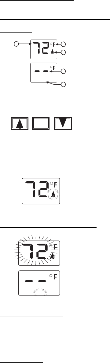
FUNCTIONS
1. ROOM TEMP – Current room temperature.
2. F – Degrees Fahrenheit (C Indicates degrees Celsius)
3. FLAME ICON – Indicates APPLIANCE IS ON.
4. SET- Indicates transmitter is in thermostat mode.
5. DASHES – Indicate thermostat mode is being disabled. When
transmitter is not in the thermostat mode. The word (SET) will not appear.
1. This TS/R-2 Wall/transmitter has ON, OFF, and SET functions that are activated by pressing the
buttons on the face of the transmitter.
2. Upon initial use, there may be a delay of five seconds before the remote receiver will respond to the
transmitter. This is part of the system’s design. If the LCD will not come on, check the 3V-button cell
battery.
SETTING MANUAL OPERATION
1. When the ON button on the wall/transmitter is pressed a flame icon on the LCD screen wil appear
when the appliance is ON.
2. When the appliance is OFF the flame icon will not appear.
SETTING THREMOSTAT OPERATION
1. If the transmitter is in the thermostat mode the word (SET) will appear on the LCD screen.
2. When the SET button is pressed the temperature digits will begin to flash.
3. While the temperature digits are flashing use the ON button to increase the set temperature or
use the OFF button to decrease the set temperature to your desired temperature.
4. When the desired temperature setting is reached press the SET button, again and the word SET
will appear on the LCD screen and now the transmitter will automatically send an ON or OFF
signal to the receiver.
5. To disengage the thermostat mode push and hold the SET button until (2) dashes appear on the
LCD screen. When you release the SET button this will disengage the thermostat mode and the
word SET will disappear from the LCD screen.
SETTING 0 F / 0 C SCALE
The factory setting for temperature is degrees Fahrenheit ( 0 F ) . To change this setting to Centigrade (0 C ), you must press and hold both the
ON and OFF buttons on the transmitter at the same time until the LCD displays the change. If you want to convert back, repeat the above
procedure.
BATTERY LIFE
Life expectancy of alkaline batteries in the SKYTECH TS/R-2 should be at least 12 months. Replace all batteries annually. When the wall
thermostat no longer operates the receiver. Or the remote receiver does not function at all; the batteries should be checked. It is important that
the remote receiver batteries are fully charged, providing a combined output voltage of at least 5.3 volts. The length of the wire between the
remote receiver and the gas valve directly affects the operating performance of the remote system. The longer the wire, the more battery
power is required to deliver signals between the remote receiver and the gas valve. The wall thermostat should operate with as little as 4.0
volts battery power, Measured at the (2) 3 volt button cell batteries.
ROOM TEMP
12
3
SET
ROOM TEMP
SET
5
4
ROOM TEMP
ROOM TEMP
SET
ROOM TEMP
SET
ON
SET
OFF