Sleipner Motor AS RCT2 Handhel Radio Control Transmitter User Manual
Sleipner Motor AS Handhel Radio Control Transmitter Users Manual
UserManual.wiki
>
Sleipner Motor AS
>
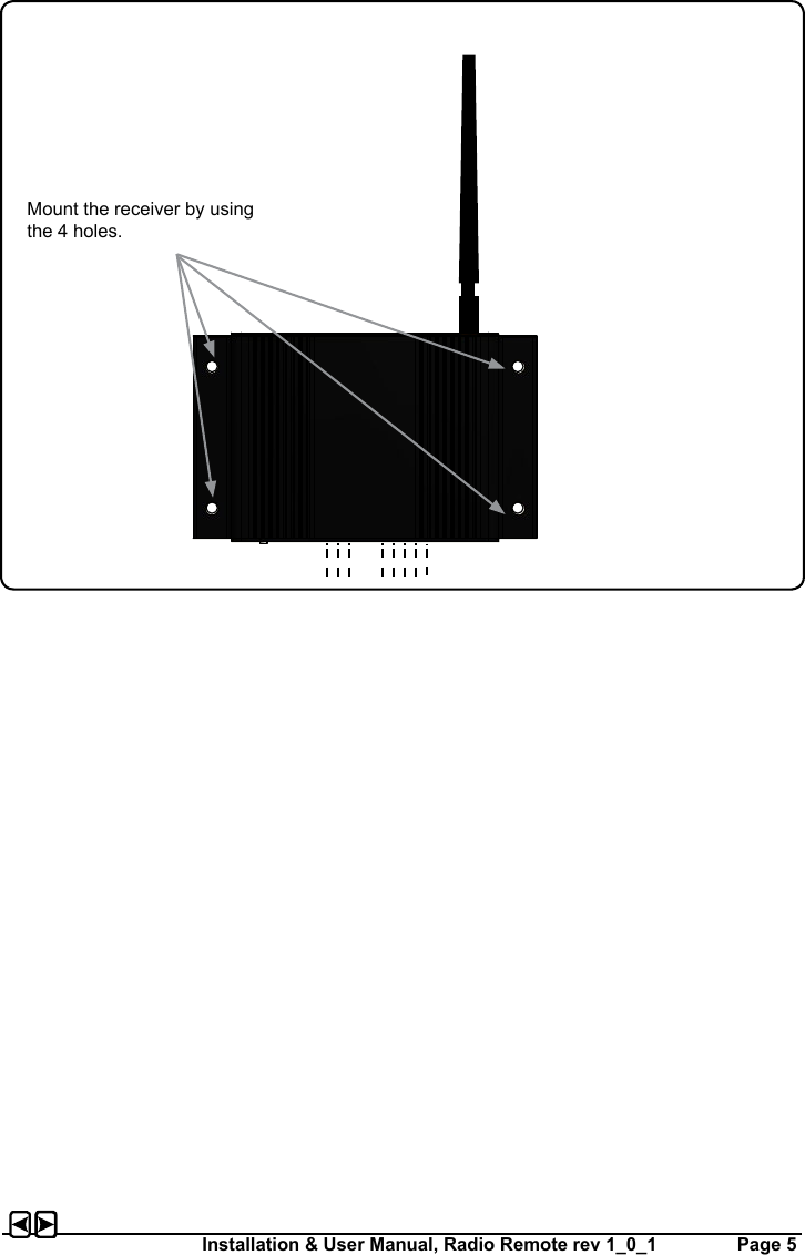
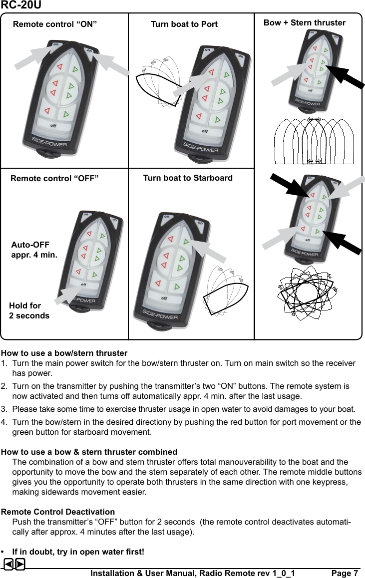
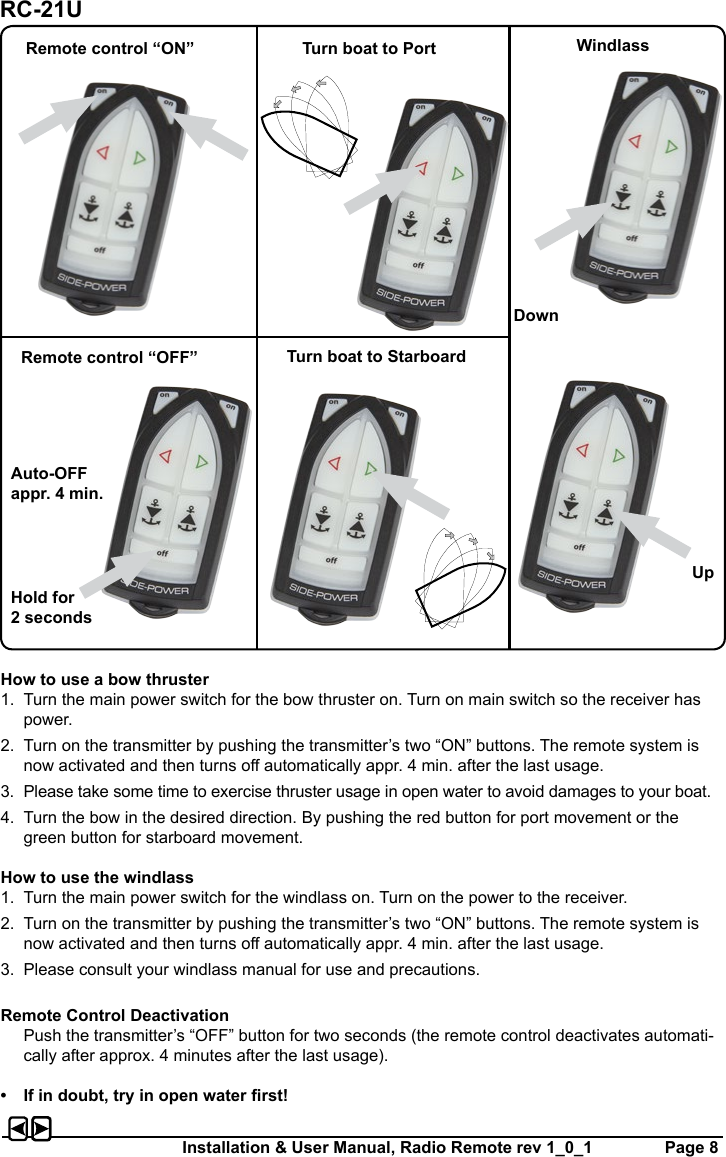
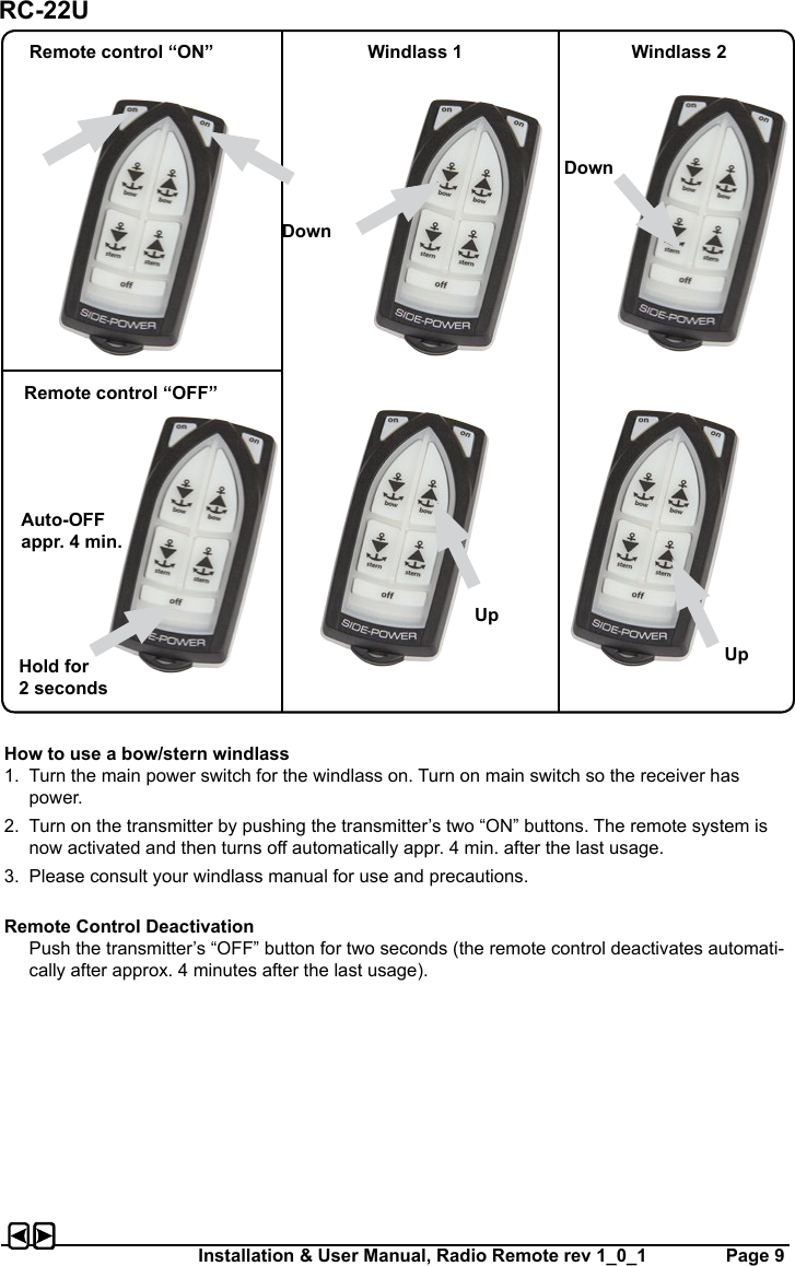
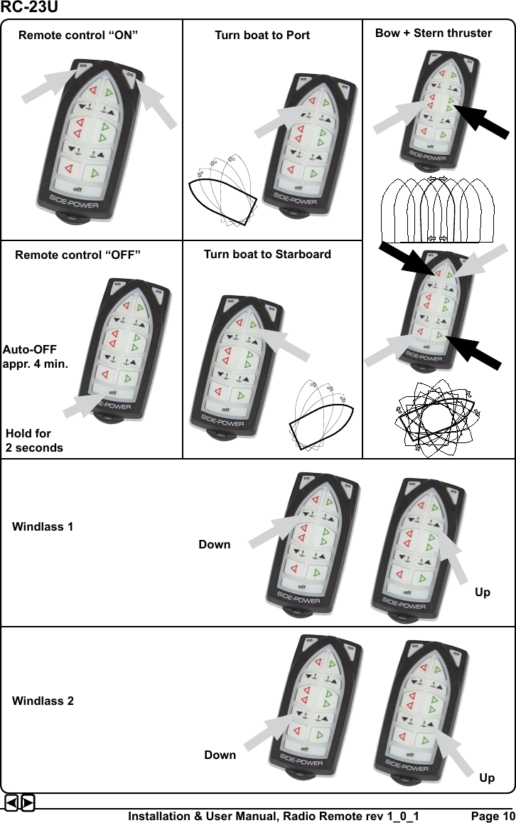
RCT2 User Manual
Users Manual
Navigation menu
Upload a User Manual
Namespaces
Wiki Guide
HTML
PDF
Info
Views
User Manual
Discussion / Help
Navigation