Sleipner Motor AS RCT2 Handhel Radio Control Transmitter User Manual
Sleipner Motor AS Handhel Radio Control Transmitter Users Manual
Users Manual
Installation & User Manual
Radio Remote v1.0.1
Made in Norway
© Sleipner Motor AS 2018
SLEIPNER MOTOR AS
P.O. Box 519
N-1612 Fredrikstad
Norway
www.side-power.com
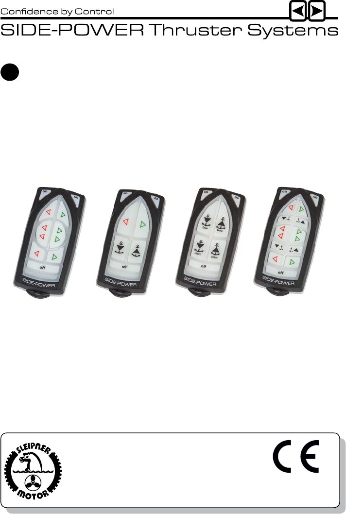
RC-20U RC-21U RC-22U RC-23U
EN

Installation & User Manual, Radio Remote rev 1_0_1 Page 2
We Sleipner Motor AS declare that this
device complies with health and safety
requirements according to the Directives
EN301 489-3 V1.4.1:2002
EN301 489-1 V1.4.1:2008
IEC 60533:1999
EN300 220-1 V2.3.1:2010
EN300 220-2 V2.3.1:2010
The radio remote control can control a single bow thruster/windlass or a bow and stern thruster/
windlass combined. The receiver can receive the signals of up to four transmitters/remote con-
trols.
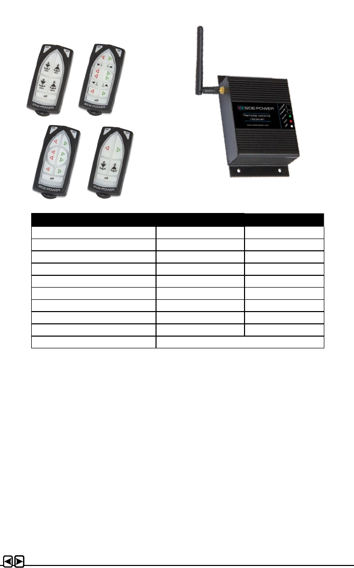
Remote control kit RC-20U consists of:
- Receiver: Part no. RCR-2U
- Transmitter (incl. battery): Part no. RCT-20U
- Holding bracket for transmitter unit: Part no. RC-HOLDER
Remote control kit RC-21U consists of:
- Receiver: Part no. RCR-2U
- Transmitter (incl. battery): Part no. RCT-21U
- Holding bracket for transmitter unit: Part no. RC-HOLDER
Remote control kit RC-22U consists of:
- Receiver: Part no. RCR-2U
- Transmitter (incl. battery): Part no. RCT-22U
- Holding bracket for transmitter unit: Part no. RC-HOLDER
Remote control kit RC-23U consists of:
- Receiver: Part no. RCR-2U
- Transmitter (incl. battery): Part no. RCT-23U
- Holding bracket for transmitter unit: Part no. RC-HOLDER
Additional transmitters/remote controls can be ordered separately;
The transmitter and the receiver have the same factory preset code so no programming is neces-
sary. The battery is already inserted in the transmitter.
When additional transmitters/remote controls are to be used, the new transmitter(s) must be
paired with the receiver (please see programming section).
Model range................................................................................................................................ 2
Technical specications .............................................................................................................. 3
Important precautions ................................................................................................................. 3
Receiver installation ................................................................................................................... 4
User precautions ........................................................................................................................ 6
How to use RC-20U..................................................................................................................... 7
How to use RC-21U..................................................................................................................... 8
How to use RC-22U..................................................................................................................... 9
How to use RC-23U................................................................................................................... 10
Transmitter LED operation and alarm indication ....................................................................... 12
Electric diagram ......................................................................................................................... 13
Output signals diagram.............................................................................................................. 14
Programming additional transmitters/remote controls ............................................................... 15
Replacing transmitter battery.................................................................................................... 16
Dimensions .............................................................................................................................. 17
Safety Information ................................................................................................................... 18
Model range
Contents
Installation & User Manual, Radio Remote rev 1_0_1 Page 3
• With the boat on land, only run the thruster for a fraction of a second, as without resistance it
will accelerate very fast to a damaging rpm.
• This manual is intended to support educated / experienced sta.
• When installed in boats approved or classied according to international or special national
rules, the installer is responsible for following the demands in accordance with these regula-
tions / classication rules. The instructions in this guide can not be guaranteed to comply with
all dierent regulations / classication rules.
• The transmitter and the receiver have the same factory preset code so no programming is
necessary. When additional transmitters/remote controls are to be used, follow the instructions
in the programming section on page 15.
Compass safe distance:
- RCT-2xxU: 0,3m
- RCR-2U: 0,2m
Technical specications
Important precautions
Transmitter Receiver
Power feed 1x3V battery (type: CR2032) 12V or 24V power source
Frequency (MHz) 914-917 MHz 914-917 MHz
RF-power <10mW <10mW
Operation temp. -10°C / +55°C -15°C / +55°C
HxWxD (mm) 107x47x21 83x136x36
Weight (g) 60 275
Voltage 8-30V
Standby power <300mW
Load, max 4A
Operating range 30m under normal operating conditions

Installation & User Manual, Radio Remote rev 1_0_1 Page 4
Prior to installation, it is important that the responsible installer reads this guide to ensure
necessary acquaintance with this product.
WARNING!
• Install the receiver minimum 1 meter (3ft) from high power cables and data communication
cables or other sources of electrical interference, i.e. navigation instruments, radio communica-
tion devices, electric motors and generators.
• Install the receiver minimum 1 meter (3ft) above sea level.
• Install the receiver outside of shielded areas for radio signals, i.e. boxes made of metals or
other material with shielding properties.
• Install the receiver in a dry environment, where no condensation can enter the unit. (The
receiver assembly is not waterproof.).
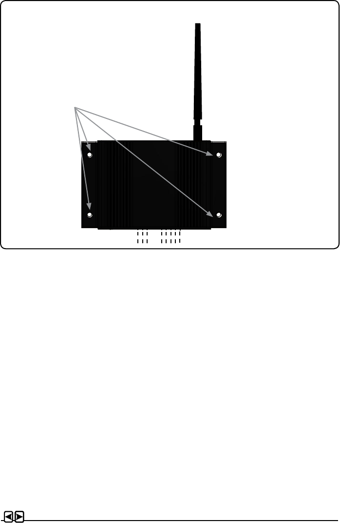
• Mount the receiver using the four holes (please see picture on page 5).
• The receiver must have a separate power supply tted with a 5 Amp fuse in the positive lead
that has either a separate power switch or is shut of by the thrusters system main power
switch. The receiver can not be powered by the thrusters/windlass control looms even if you
nd positive and negative lead there.
• Connect the supplied wiring harnesses to the receiver unit according to the wiring diagram
on page 13. Connect thrusters and windalsses to the appropirate connectors according to
diagram.
• For use with other windlass brands, connections must be determined by the installer according
to output signals diagram on page 14.
NB: Max. load on the windlass signal output is 4A!
If the windlass requires more than 4A, use extra control relay.
Note! Faulty installation will render all warranty given by Sleipner Motor AS void.
Receiver installation
WARNING!
Remote receiver power supply negative lead must be connected to the thrusters`s
negative lead. Bow and stern thruster must have common negative. Power to the
thruster’s must be switched o during installation!
Installation & User Manual, Radio Remote rev 1_0_1 Page 5
Mount the receiver by using
the 4 holes.
1
1
2
2
3
3
4
4
5
5
6
6
A A
B B
C C
D D
olekr 18.08.2015
Designed by Checked by Approved by Date
1 / 1
Edition Sheet
Date

Installation & User Manual, Radio Remote rev 1_0_1 Page 6
• Ensure that you know the location of the main battery switch that disonnects the thruster from
all power sources (batteries) so that the thruster/windlass can be turned o in case of a mal-
function.
• The maximum continues usage time of the electrical thruster is approx. 3 minutes. The electro
motor has a built in thermal cut-o switch that will shut it o when overheating and re-engage it
when it has cooled down some. This should be considered when planning your manouvering.
• Never use a thruster close to somebody in the water, as the thruster will draw objects close by
into the tunnel and contact with the rotating propellers will cause serious injuries.
• Never use a windlass close to somebody in the water, an unexpectedly drop of the anchor can
cuse serious injuries.
• If the thruster stops giving thrust while the electric motor is running, chances are that there is a
problem in the drive-system. You must then immediately stop trying to run it, and turn it o, as
running the electricmotor for more than a few seconds without resistance from the propeller,
can cause serious damage to the electricmotor.
• When leaving the boat always turn o the main power switch for the thruster/windlass and turn
o the power to the receiver.
• We advice to always keep the main engine(s) running while using a thruster/windlass. This
will keep the batteries in a good charge condition. This will also give better performance to the
thruster.
• It is the owner/captain/other responsible party full responsibility to assess the risk of any
unexpected incidents on the vessel. If the thruster stops giving thrust for some reason while
maneuvering you must have considered a plan on how to avoid damage to persons or other
objects.
User precautions
Installation & User Manual, Radio Remote rev 1_0_1 Page 7
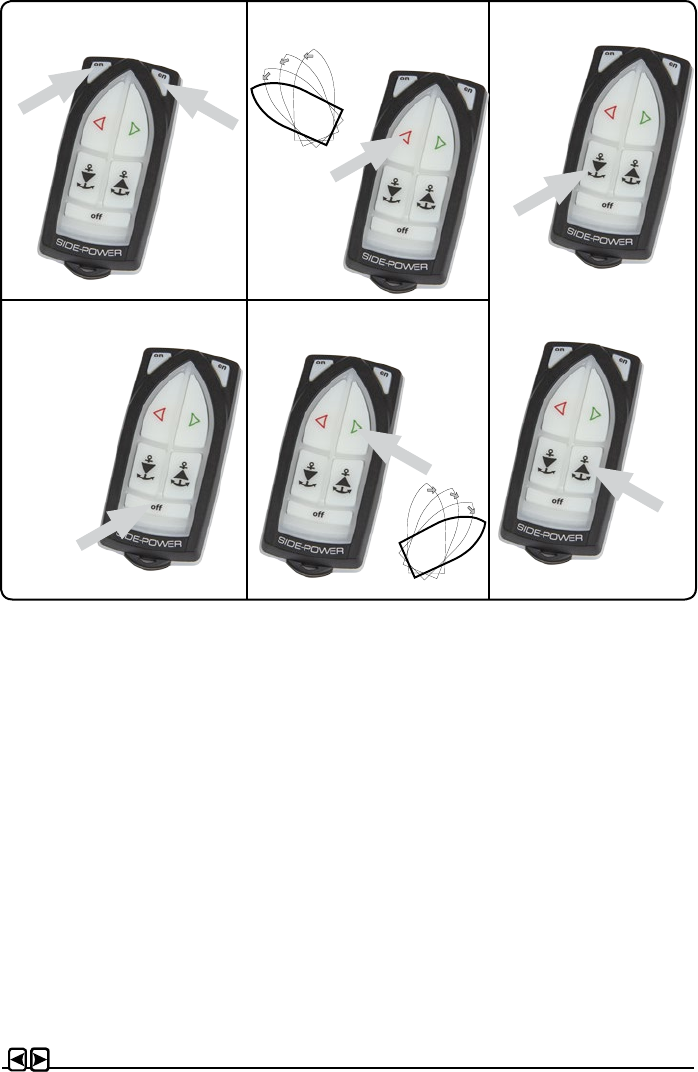
How to use a bow/stern thruster
1. Turn the main power switch for the bow/stern thruster on. Turn on main switch so the receiver
has power.
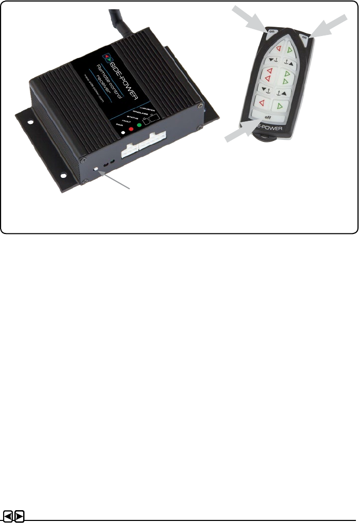
2. Turn on the transmitter by pushing the transmitter’s two “ON” buttons. The remote system is
now activated and then turns o automatically appr. 4 min. after the last usage.
3. Please take some time to exercise thruster usage in open water to avoid damages to your boat.
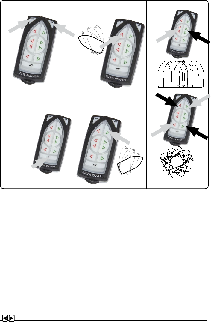
4. Turn the bow/stern in the desired directiony by pushing the red button for port movement or the
green button for starboard movement.
How to use a bow & stern thruster combined
The combination of a bow and stern thruster oers total manouverability to the boat and the
opportunity to move the bow and the stern separately of each other. The remote middle buttons
gives you the opportunity to operate both thrusters in the same direction with one keypress,
making sidewards movement easier.
Remote Control Deactivation
Push the transmitter’s “OFF” button for 2 seconds (the remote control deactivates automati-
cally after approx. 4 minutes after the last usage).
• If in doubt, try in open water rst!
Remote control “ON” Turn boat to Port Bow + Stern thruster
Remote control “OFF” Turn boat to Starboard
Auto-OFF
appr. 4 min.
Hold for
2 seconds
RC-20U
Installation & User Manual, Radio Remote rev 1_0_1 Page 8
How to use a bow thruster
1. Turn the main power switch for the bow thruster on. Turn on main switch so the receiver has
power.
2. Turn on the transmitter by pushing the transmitter’s two “ON” buttons. The remote system is
now activated and then turns o automatically appr. 4 min. after the last usage.
3. Please take some time to exercise thruster usage in open water to avoid damages to your boat.
4. Turn the bow in the desired direction. By pushing the red button for port movement or the
green button for starboard movement.
How to use the windlass
1. Turn the main power switch for the windlass on. Turn on the power to the receiver.
2. Turn on the transmitter by pushing the transmitter’s two “ON” buttons. The remote system is
now activated and then turns o automatically appr. 4 min. after the last usage.
3. Please consult your windlass manual for use and precautions.
Remote Control Deactivation
Push the transmitter’s “OFF” button for two seconds (the remote control deactivates automati-
cally after approx. 4 minutes after the last usage).
• If in doubt, try in open water rst!
Remote control “ON” Turn boat to Port Windlass
Remote control “OFF” Turn boat to Starboard
Auto-OFF
appr. 4 min.
Down
Up
Hold for
2 seconds
RC-21U
Installation & User Manual, Radio Remote rev 1_0_1 Page 9
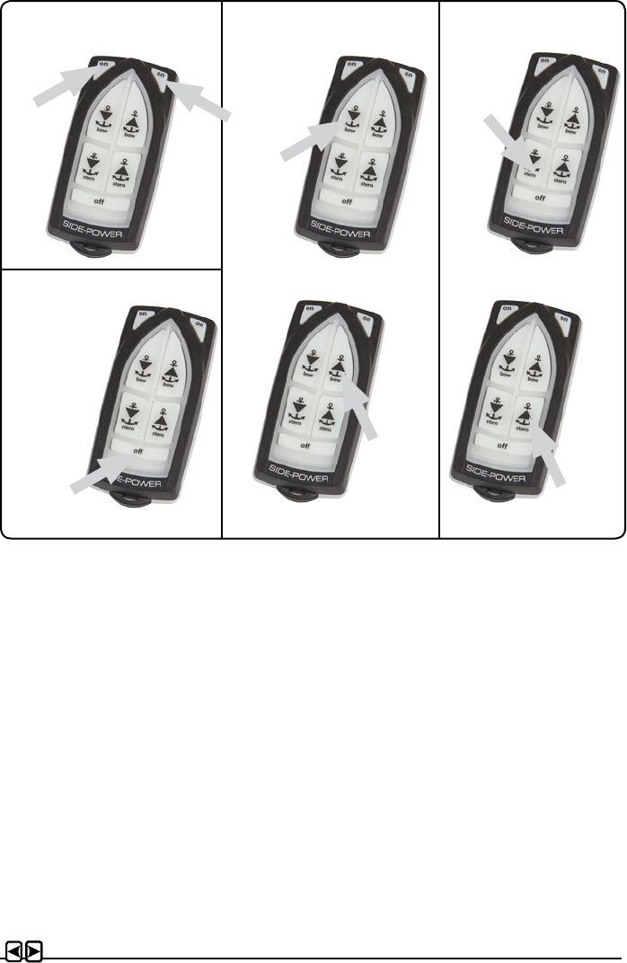
How to use a bow/stern windlass
1. Turn the main power switch for the windlass on. Turn on main switch so the receiver has
power.
2. Turn on the transmitter by pushing the transmitter’s two “ON” buttons. The remote system is
now activated and then turns o automatically appr. 4 min. after the last usage.
3. Please consult your windlass manual for use and precautions.
Remote Control Deactivation
Push the transmitter’s “OFF” button for two seconds (the remote control deactivates automati-
cally after approx. 4 minutes after the last usage).
Remote control “ON” Windlass 2
Remote control “OFF”
Auto-OFF
appr. 4 min.
Down
Up
Hold for
2 seconds
Windlass 1
Down
Up
RC-22U
Installation & User Manual, Radio Remote rev 1_0_1 Page 10
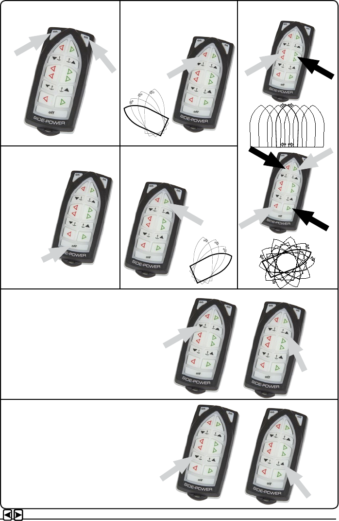
Remote control “ON” Turn boat to Port Bow + Stern thruster
Remote control “OFF” Turn boat to Starboard
Auto-OFF
appr. 4 min.
Hold for
2 seconds
RC-23U
Windlass 2
Down
Up
Windlass 1
Down
Up

Installation & User Manual, Radio Remote rev 1_0_1 Page 11
How to use a bow/stern thruster
1. Turn the main power switch for the bow/stern thruster on. Turn on main switch so the receiver
has power.
2. Turn on the transmitter by pushing the transmitter’s two “ON” buttons. The remote system is
now activated and then turns o automatically appr. 4 min. after the last usage.
3. Please take some time to exercise thruster usage in open water to avoid damages to your boat.
4. Turn the bow/stern in the desired directiony by pushing the red button for port movement or the
green button for starboard movement.
How to use a bow & stern thruster combined
The combination of a bow and stern thruster oers total manouverability to the boat and the
opportunity to move the bow and the stern separately of each other. The remote middle buttons
gives you the opportunity to operate both thrusters in the same direction with one keypress,
making sidewards movement easier.
How to use the bow/stern windlass
1. Turn the main power switch for the windlass on. Turn on the power to the receiver.
2. Turn on the transmitter by pushing the transmitter’s two “ON” buttons. The remote system is
now activated and then turns o automatically appr. 4 min. after the last usage.
3. Please consult your windlass manual for use and precautions.
Remote Control Deactivation
Push the transmitter’s “OFF” button for two seconds (the remote control deactivates automati-
cally after approx. 4 minutes after the last usage). Turn o the power switch for the receiver.
• If in doubt, try in open water rst!

Installation & User Manual, Radio Remote rev 1_0_1 Page 12
Transmitter LED operation and alarm indication
State LED status Alarm status
Transmitter ON The yellow LED’s
blink each second
No sound
Buttons activated The yellow LED’s
blink fast
No sound
Pairing mode All LED’s on No sound
Connection lost Red LED is blink-
ing once each
second
3 beeps from the
buzzer each second
Low battery Red LED blink One beep
State LED status
Power on the receiver and no transmitter connected Green LED is toggling
Power on the receiver and at least one transmitter
connected
Green LED lit
No power to the receiver. Both LED is o
Receiver in pairing mode Both the red and
green LED blinking
Receiver LED indicator
Installation & User Manual, Radio Remote rev 1_0_1 Page 13
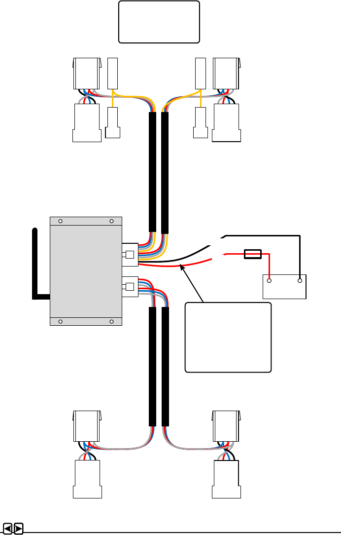
Electric diagram
RED
BLACK
BOW STERN
STERN
BOW
To Bow
Thruster
To Stern
Thruster
To Thruster
Control Panel
To Windlass
Control Panel
To Thruster
Control Panel
To Windlass
Control Panel
To Bow
Windlass
To Stern
Windlass
Battery 12/24V
+ -
FUSE
5A
Remember!
Power cables must
be connected to the
battery as shown.
Remaining wires must
be cable tied well.
Remember!
Cables/wires must be
cable tied well.

Installation & User Manual, Radio Remote rev 1_0_1 Page 14
Output signals diagram
RED – Thruster Pos itive
BLUE – Thruster STBD
GREY – Thruster PORT
YELLOW – Automatic Mainswitch Enable
RED - COMMON
BLUE – Windlass IN
GREY – Windlass O UT
RED – Thruster P os itive
BLUE – Thruster STBD
GREY – Thruster PORT
YELLOW – Automatic Mainswitch Enable
RED - COMMON
BLUE – Windlass IN
GREY – Windlass O UT
Thruster Bow
Th ruster Stern
Windlass Bow
Windlass Stern
Installation & User Manual, Radio Remote rev 1_0_1 Page 15
The original transmitter and receiver have the same factory preset code so that no programming
is necessary. When additional transmitters/remote controls are to be used, the additional transmit-
ters/remote controls has to be paired with the receiver.
1. Be sure that there is power on the receiver (Green status LED blinking) and that the transmit-
ter that should be paired is o.
2. Push the Pair Button on the receiver to put the receiver in pairing mode (as shown above).
Both red and green led’s should start to blink simultaneously.
3. Within 10s after the receiver pair button is pushed, set the transmitter in pairing mode by
holding the o button and pressing both “ON” buttons at the same time, all the transmitter
LED’s turn on indicating that it is set in pairing mode. When a pairing signal is received from
the receiver the transmitter LED’s while turn o and the system is ready to be used. If no
pairing signal received within 10s the transmitter will leave the pairing mode.
4. Additional transmitters/remote controls must be programmed according to step 2-3. You can
pair up to 4 transmitters/remote controls.
5. To clear all transmitters/remote controls paired with the receiver hold the pair button on the
receiver for approximately 10s until the red and green led stop blinking. When the LED’s stop
blinking release the pair button, the green led will again start to blink when the receiver has
completed the reset process. The receiver is then ready to pair with up to four transmitters/
remote controls.
Programming additional Transmitters/Remote controls
Pair Button
Installation & User Manual, Radio Remote rev 1_0_1 Page 16
WARNING:
Before working on the transmitter, deactivate the transmitter and the receiver (push “OFF” on the
transmitter(s)) and turn o the power to the receiver as well as the thruster mainswitch.
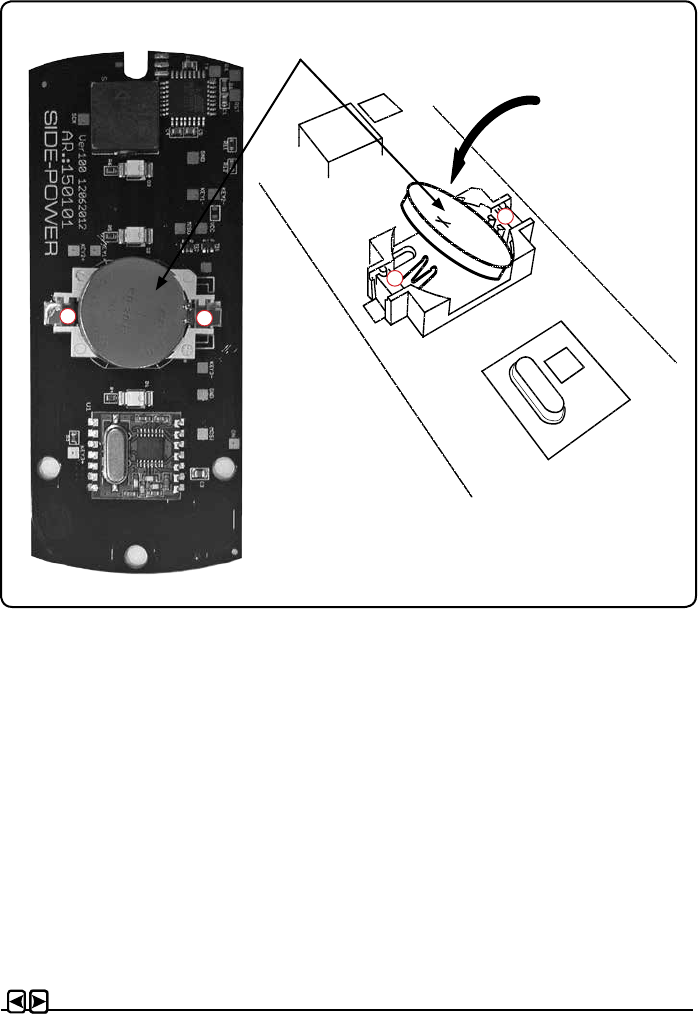
1. Open the transmitter case by removing the 3 torque screws.
2. Remove the battery by inserting a screwdriver or similar between battery and holder at point A,
and gently ip the battery out, taking care not damaging the battery grips at point B.
3. Insert the new battery (Type CR2032, 3V - Brand name recommended). Be sure to insert the
battery with the positive pole up diagonally into the battery holder, ensuring that the edge of the
battery is under the battery grips (B). Press the battery down until secured at point A.
4. Close the transmitter. Put the cover back in place, ensure that the rubber seal between remote
upper and lower part is located correctly. Place the 3 screws (remember sealing washer) in
their recessed holes and tighten.
Replacing transmitter battery
Battery
A
B
AB
Installation & User Manual, Radio Remote rev 1_0_1 Page 17
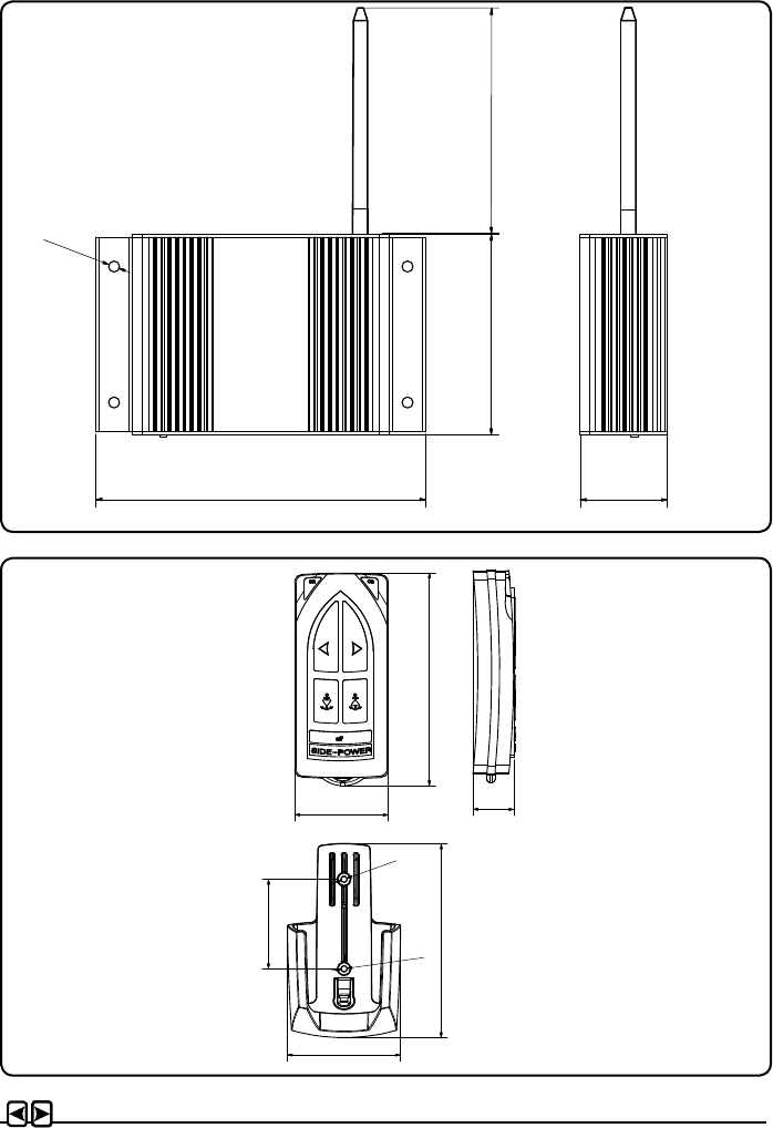
Dimensions
1
1
2
2
3
3
4
4
5
5
6
6
7
7
8
8
A A
B B
C C
D D
E E
F F
8927
13.10.2015
1
Designed by Date
1 / 1
Edition Sheet
olekr
Material Type
Generic
Drawing nr
8927 Holder
Copyright All rights reserved
Part nr Size Scale
Title Holder
Tolerance NS-ISO 2768-1
SLEIPNER MOTOR AS
A2
0,016 kg
Weight
(old version 8981/8986)
NS-ISO 2768-1
Over t.o.m. f m c v
0,5 3 ±0,05 ±0,1 ±0,2 -
3 6 ±0,05 ±0,1 ±0,3 ±0,5
6 30 ±0,1 ±0,2 ±0,5 ±1
30 120 ±0,15 ±0,3 ±0,8 ±1,5
120 400 ±0,2 ±0,5 ±1,2 ±2,5
400 1000 ±0,3 ±0,8 ±2 ±4
1000 2000 ±0,5 ±1,2 ±3 ±6
2000 4000 - ±2 ±4 ±8
3
3
45
57
97
107
47 21
4,5 x4
136
83
36
112
1
1
2
2
3
3
4
4
5
5
6
6
7
7
8
8
A A
B B
C C
D D
E E
F F
8927
13.10.2015
1
Designed by Date
1 / 1
Edition Sheet
olekr
Material Type
Generic
Drawing nr
8927 Holder
Copyright All rights reserved
Part nr Size Scale
Title Holder
Tolerance NS-ISO 2768-1
SLEIPNER MOTOR AS
A2
0,016 kg
Weight
(old version 8981/8986)
NS-ISO 2768-1
Over t.o.m. f m c v
0,5 3 ±0,05 ±0,1 ±0,2 -
3 6 ±0,05 ±0,1 ±0,3 ±0,5
6 30 ±0,1 ±0,2 ±0,5 ±1
30 120 ±0,15 ±0,3 ±0,8 ±1,5
120 400 ±0,2 ±0,5 ±1,2 ±2,5
400 1000 ±0,3 ±0,8 ±2 ±4
1000 2000 ±0,5 ±1,2 ±3 ±6
2000 4000 - ±2 ±4 ±8
3
3
45
57
97
107
47 21
4,5 x4
136
83
36
112

Installation & User Manual, Radio Remote rev 1_0_1 Page 18
Safety Information
FCC statements
Changes or modications to the equipment not expressly approved by the party responsible for
compliance could void the user's authority to operate the equipment.
This device complies with Part 15 of the FCC Rules. Operation is subject to the following two
conditions: (1) this device may not cause harmful interference, and (2) this device must accept any
interference received, including interference that may cause undesired operation.
NOTE: This equipment has been tested and found to comply with the limits for a Class B digital
device, pursuant to Part 15 of the FCC Rules. These limits are designed to provide reasonable
protection against harmful interference in a residential installation. This equipment generates,
uses and can radiate radio frequency energy and, if not installed and used in accordance with
the instructions, may cause harmful interference to radio communications. However, there is no
guarantee that interference will not occur in a particular installation.
If this equipment does cause harmful interference to radio or television reception, which can be
determined by turning the equipment o and on, the user is encouraged to try to correct the inter-
ference by one or more of the following measures:
- Reorient or relocate the receiving antenna.
- Increase the separation between the equipment and receiver.
- Connect the equipment into an outlet on a circuit dierent from that to which the receiver is con-
nected.
- Consult the dealer or an experienced radio/TV technician for help.
ISED statements
This Device complies with Industry Canada License-exempt RSS standard(s). Operation is subject
to the following two conditions: (1) this device may not cause interference, and (2) this device
must accept any interference, including interference that may cause undesired operation of the
device.
Le présent appareil est conforme aux CNR d’Industrie Canada applicables aux appareils radio ex-
empts de licence. L’exploitation est autorisée aux deux conditions suivantes : (1) l’appareil ne doit
pas produire de brouillage ; (2) l’appareil doit accepter tout brouillage radioélectrique subi, même
si le brouillage est susceptible d’en compromettre le fonctionnement.

Installation & User Manual, Radio Remote rev 1_0_1 Page 19

Worldwide sales and service
www.side-power.com
SLEIPNER MOTOR AS
P.O. Box 519 N-1612 Fredrikstad Norway
Tel: +47 69 30 00 60 Fax:+47 69 30 00 70 www.side-power.com sidepower@sleipner.no
The information given in the document was correct at the time it was published. However, Sleipner Motor AS can not accept liability for any inaccuracies or omissions it
may contain. Continuous product improvement may change the product specications without notice. Therefore, Sleipner Motor AS can not accept liability for any pos-
sible differences between product and document.