Smarfid Security Equipment REX2110EIS Contactless Door Egress Device (US Standard) User Manual
Shanghai Smarfid Security Equipment Co, Ltd. Contactless Door Egress Device (US Standard) Users Manual
Users Manual

Contactless Door Egress Device (US Standard)
Match OEM reader design in order to maximize the marketing value at the door.
Design Philosophy
Abbreviation
REX2-e – Economic Request to Exit button. Basic model without chimer and sirens.
REX2-i – Intelligent Request to Exit button. Model with chimer and sirens.
REX2-s – Safety Request to Exit Device. Model with Break Glass function.
Capacitance Proximity Technology has been used instead of Infar-red technology – environmental
independent design.
When the device is activated, indicator light will change color with an audible tone – very user friendly.
Icon indicators to alert the user for Door Held Open, Fire Alarm and Mains Failure situation.
Build-in Mechanical Override in case power failure or electronic failure.
Build-in Door Chimer to interact with the “*” sign on Magic series Number pad reader.
Build-in Fire Alarm input. If the fire input got trigger, the lock will be released automatically.
Embedded a traditional Break Glass device with “test key”. When activated, both Visible and Auditable alert will
trigger to provide better indication of the door location under emergency situation.
Support Remote Control (433MHz) to trigger the REX remotely.
Technology & Function
Friendly Installation
All input and output signals are
protected against static
charges.
Reverse power protection.
All inputs are 12Vdc protected.

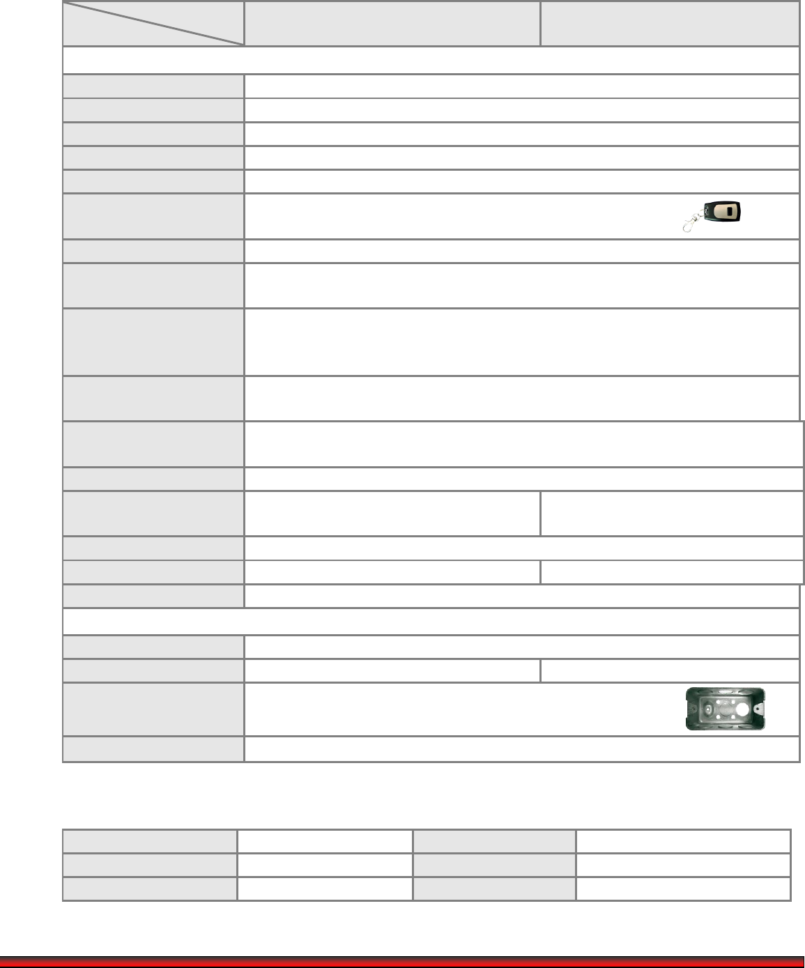
Specification:
Model
Functions
REX2-i
REX2-s
Functional Specification
Request to Exit indication
Color changes from Blue to Green with a beep
Request to Exit output
Dry contact output for 1 seconds (NC/NO selectable)
RTE Output (dry contact)
NC/NO jumper selectable rated @ 30Vdc; 1A
Mechanical Override
Available for all models
Tamper protection
Available for all models
Remote Button (Optional)
433.896MHz
(Max supports 5 remote buttons at the same time.)
Alarm Output
Dry contact output follow the Fire input (NC/NO selectable)
Door Held Open
Indication icon
The icon will change to blue and beep every 5 seconds
Door Held Open
High/Low level input
jumper
High/Low level input jumper selectable
Buzzer for DHO and RTE
activate
Jumper enable/disable
Main Power failure
Indicator
Mains failure dry contact output from Power Supply.
The icon will change to orange when activated
Fire Alarm Indicator
The icon will change to red and siren will activated
Fire Alarm Input
When trigger, back lit will flash in Red the siren will
activate
When trigger, the lock will release and back
lit will flash in Red & siren will activate
Speaker
Equipped for Door Chimer and Siren
“Break Glass” function
N/A
Hit hard at the center
Dimension
118.2 (L) X 74.2 (W) X 8.5 (H) mm (above surface)
Technical Specifications
Typical Read range
~3 to 4cm
Electric Lock bypass relay
N/A
30Vdc; 2A (max)
Electric Box
Requirement
Please make sure the gang box is similar to the diagram as display.
Weight
157g
Operating Specification:
Operating Voltage
9 - 15VDC
Case material
PC+ABS
Operating Current
150mA (max @ 12Vdc)
Standard Color
Black & White
Operating Temperature
-20℃-60℃
Operating Humidity
10% - 90%
FCC STATEMENT
1. This device complies with Part 15 of the FCC Rules. Operation is subject to the following two
conditions:
(1) This device may not cause harmful interference.
(2) This device must accept any interference received, including interference that may cause
undesired operation.
2. Changes or modifications not expressly approved by the party responsible for compliance could
void the user's authority to operate the equipment.
NOTE: This equipment has been tested and found to comply with the limits for a Class B digital
device, pursuant to Part 15 of the FCC Rules. These limits are designed to provide reasonable
protection against harmful interference in a residential installation.
This equipment generates uses and can radiate radio frequency energy and, if not installed and
used in accordance with the instructions, may cause harmful interference to radio communications.
However, there is no guarantee that interference will not occur in a particular installation. If this
equipment does cause harmful interference to radio or television reception, which can be
determined by turning the equipment off and on, the user is encouraged to try to correct the
interference by one or more of the following measures:
Reorient or relocate the receiving antenna.
Increase the separation between the equipment and receiver.
Connect the equipment into an outlet on a circuit different from that to which the receiver is
connected.
Consult the dealer or an experienced radio/TV technician for help.