Smart Approach MAB03NFCAM NFC Antenna Module User Manual MAB03 UserMan
Smart Approach Co., Ltd. NFC Antenna Module MAB03 UserMan
(MAB03) UserMan
BCM EvB
Application Guide
Smart Approach
Smart Approach BCM EvB Application Guide
- 2 -
Revision 1.0, September 2013
Corporate Headquarters
4F,No.669,Sec.4.ChungHsing Rd.,
Chutung,Hsinchu 310,
Taiwan,R.O.C.
www.smart-approach.com.tw
Copyright©2007-2013, by Smart Approach Co., Ltd.
Smart Approach Co., Ltd (“S.A.”) retains the right to make changes to its
products or specifications to improve performance, reliability or
manufacturability. All information in this document, including descriptions of
features, functions, performance, technical specifications and availability, is
subject to change without notice at any time. While the information furnished
herein is held to be accurate and reliable, no responsibility will be assumed by
Smart Approach for its use. Furthermore, the information contained herein
does not convey to the purchaser of microelectronic devices any license under
license under the patent right of any manufacturer.
Smart Approach Co., Ltd is a registered trademark. All other products or
service names used in this publication are for identification purposes only, and
may be trademarks or registered trademarks of their respective companies. All
other trademarks or registered trademarks mentioned herein are the property
of their respective holders.

Smart Approach BCM EvB Application Guide
- 3 -
Revision 1.0, September 2013
Contents
REVISION HISTORY ................................................................................................................... - 4 -
CHAPTER 1 INTRODUCTION ........................................................................................................... - 5 -
1.1. ELECTRIC SAFETY .............................................................................................................. - 5 -
1.2. OPERATE SAFETY ............................................................................................................... - 5 -
1.3. ABOUT THIS GUIDE ............................................................................................................. - 5 -
1.4 NFC ANTENNA MODULE APPLICATIONS ........................................................................................ - 6 -
CHAPTER 2 INTRODUCES OF ANTENNA MODULE ........................................................................... - 7 -
CHAPTER 3: ANTENNA MODULE ENGAGED AND INSTALLATION ..................................................... - 8 -
3.1 STARTUP PROCEDURES ................................................................................................................ - 9 -
FEDERAL COMMUNICATIONS COMMISSION INTERFERENCE STATEMENT ..................................... - 12 -
Figure Contents
Figure 1 Application of Antenna Module ........................................... - 6 -
Figure 2 Antenna Module Front View ................................................ - 7 -
Figure 3 Antenna Module Rear View ................................................. - 7 -
Figure 4 Application Component ........................................................ - 8 -
Smart Approach BCM EvB Application Guide
- 4 -
Revision 1.0, September 2013
Revision History
This section describes the changes that were implemented in this document.
The changes are listed by revision, starting with the most current publication.
Revision 1.0
Revision 1.0 of this guide was published in September 2013. This was the first
publication of the document.

Smart Approach BCM EvB Application Guide
- 5 -
Revision 1.0, September 2013
Chapter 1 Introduction
Safety:
1.1. Electric Safety
To avoid the suddenly electricity cause equipment damaged, please have all
connectors linked before turn on the power.
1.2. Operate Safety
Please read this manual carefully before install.
Please confirm all wires are putting into the right place and linked well.
1.3. About this Guide
This product guide included all the information you need in the EvB test.
Examples of application designs and technologies are also provided to
illustrate the points made and to demonstrate the flexibility offered in achieving
the advanced NFC function performance improvement provided within the
guide. Additional bonus recommendations point out other opportunities to
incorporate greater performance improvement into the design of the
application.
Feedback on the use of any of the guide is welcomed and encouraged by
Smart Approach.
Smart Approach BCM EvB Application Guide
- 6 -
Revision 1.0, September 2013
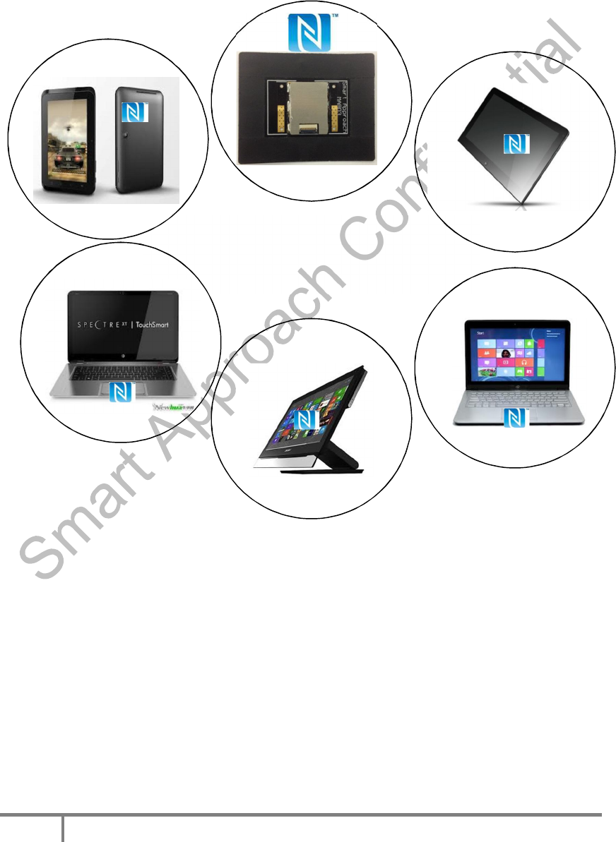
1.4 NFC Antenna module applications
NFC Antenna Module can be installed under the Touch Pad of notebook,
ultrabook , AIO, and personal computers, it can achieve Wireless payment and
to read NFC single in different NFC devices.
NFC can make the process of identify much easier, more accuracy, much
safer, and more limpid. You can link all your electricity devices via NFC to
make the information transiting much easier.
Figure 1 Application of Antenna Module
Under touch pad for ultrabook /
notebook /AIO
Smart Approach BCM EvB Application Guide
- 7 -
Revision 1.0, September 2013
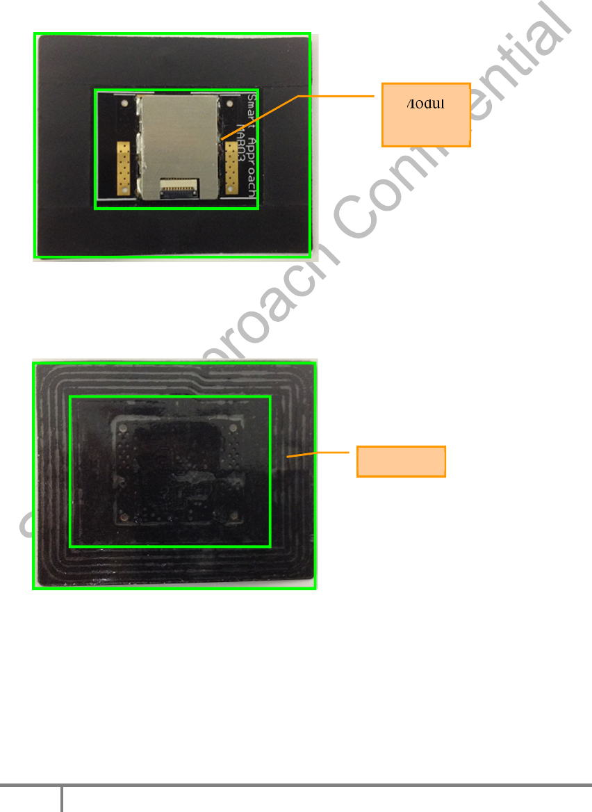
Chapter 2 Introduces of Antenna Module
Module
Antenna
Connector
Shielding。
Combine above 4 elements, we named it “Antenna Module”, it is light,
short, small and thin to integrate into NB, tablets and smartphones.
as pic below
Figure 2 Antenna Module Front View
Figure 3 Antenna Module Rear View
Antenna
Module
Smart Approach BCM EvB Application Guide
- 8 -
Revision 1.0, September 2013
Chapter 3: Antenna Module engaged and Installation
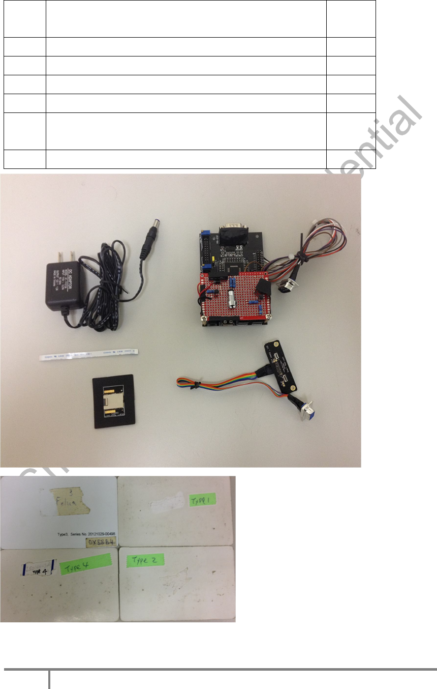
Electricity requirement of NFC Antenna Module.
Step/
Item
ITEM NAME Q’TY
Host(Simulates the computer MB) 1
Power Adapter(Supply electric to Host) 1
Wire 1
Antenna Module 1
Wire with Transition board
(10 pin to 9 pin connection for Host) 1
Proximity Card (Type1、Type2、Type3、Type4) 1/each
Figure 4 Application Components
Smart Approach BCM EvB Application Guide
- 9 -
Revision 1.0, September 2013
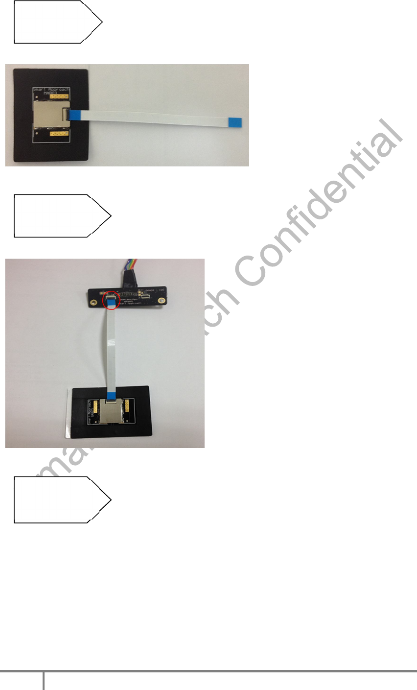
3.1 Startup procedures
Insert the cable to the Antenna Module Connector,
shown as below:
The other end of the cable is inserted Wire adapter
plate and pressed on J2 Connector ranked carefully.
Shown as below:
The other end of the wire Transition board
to insert the connector with 9 pin at the host.
Show as below:
Step 1.
Step 2
Step 3
J2
Smart Approach BCM EvB Application Guide
- 10 -
Revision 1.0, September 2013
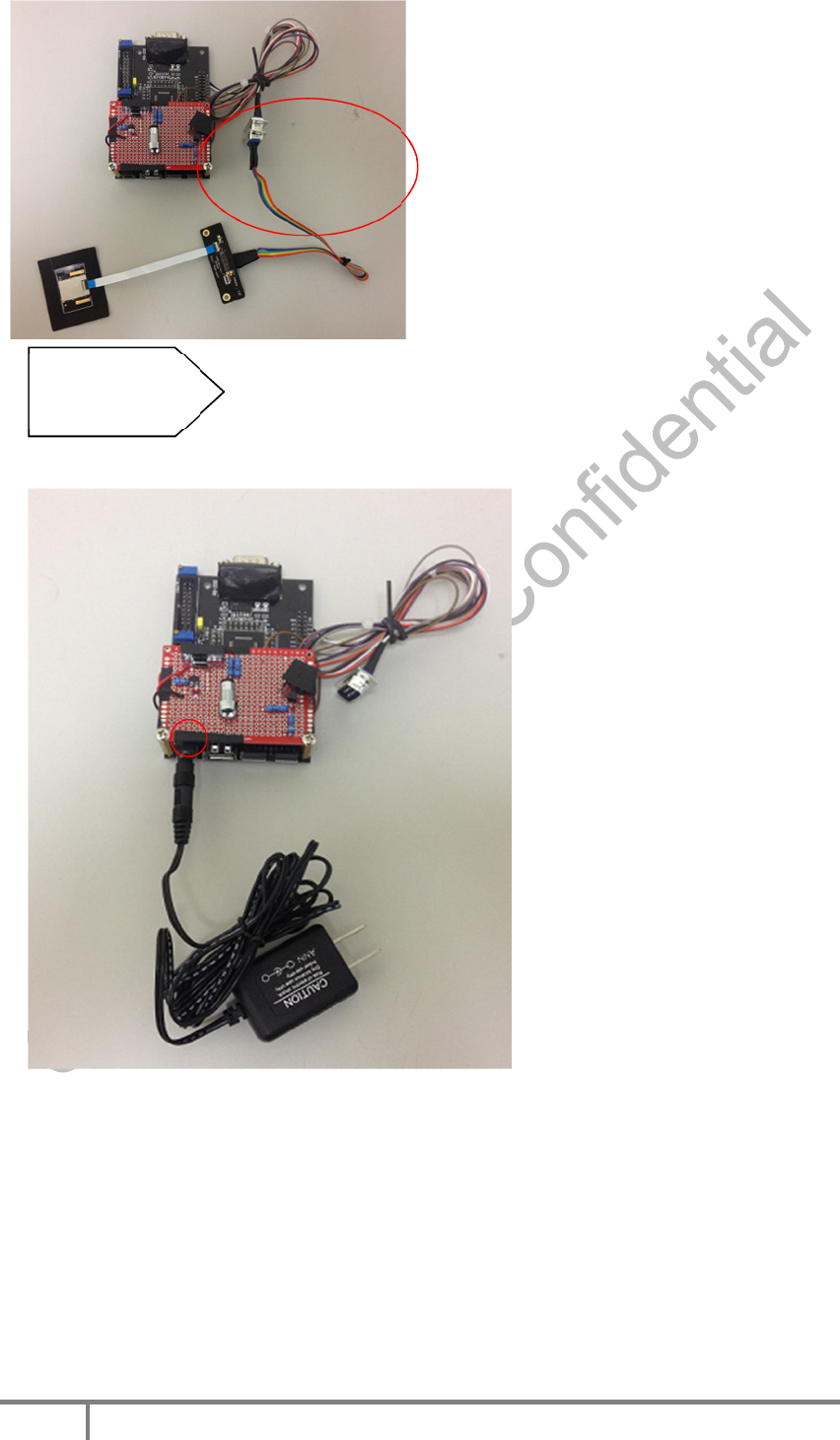
Insert the DC input connector into the Host DC 5V
input terminal. Show as below.
CONNECTOR
WITH 9 PIN
Step 4
DC 5V
Smart Approach BCM EvB Application Guide
- 11 -
Revision 1.0, September 2013
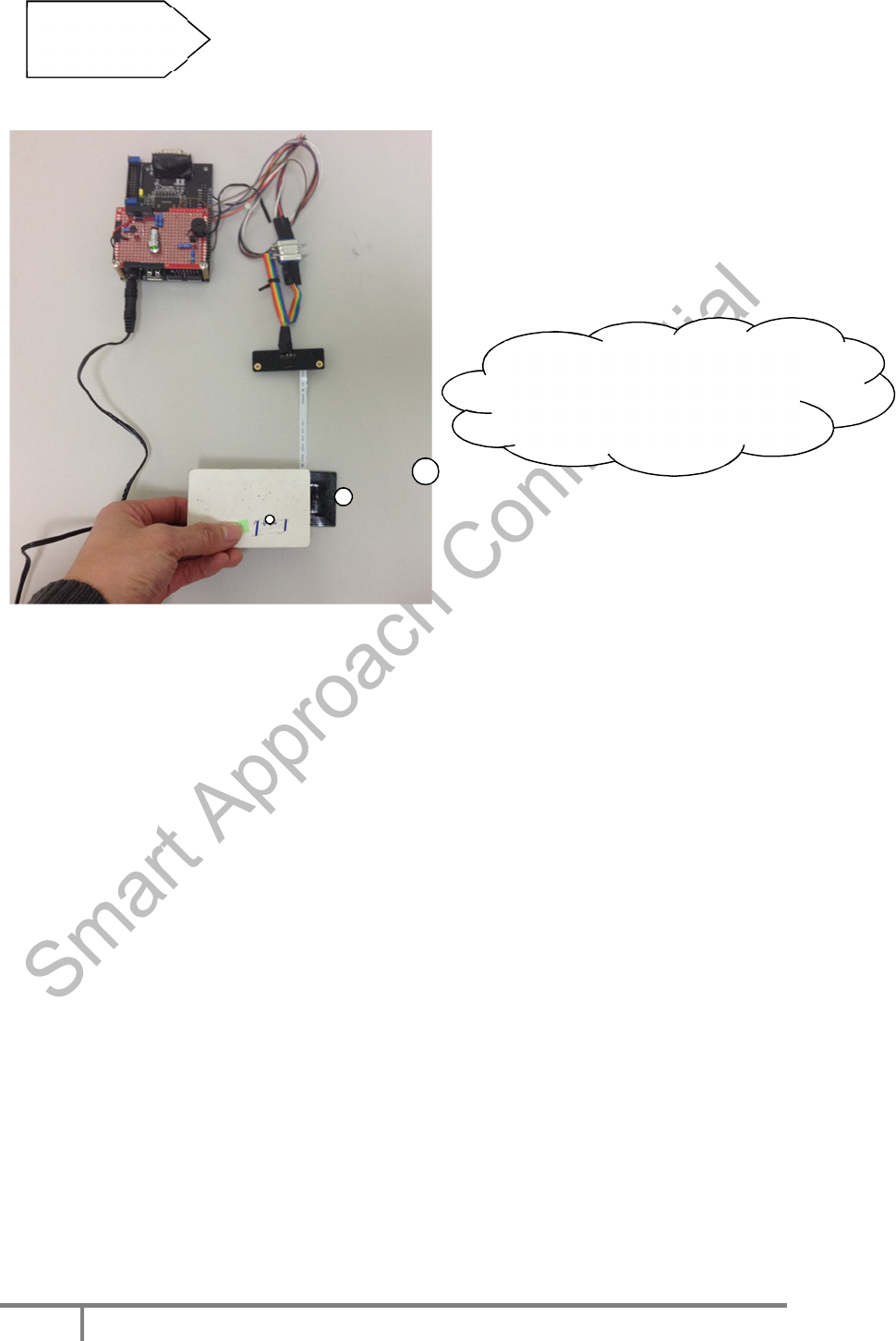
Antenna Module induced the cards after Host power on.
Step 5
Takeclose toAntenna
Module

Smart Approach BCM EvB Application Guide
- 12 -
Revision 1.0, September 2013
FEDERAL COMMUNICATIONS COMMISSION
INTERFERENCE STATEMENT
This equipment has been tested and found to comply with the limits for a Class
B digital device, pursuant to part 15 of the FCC Rules. These limits are
designed to provide reasonable protection against harmful interference in a
residential installation. This equipment generates, uses and can radiate radio
frequency energy and, if not installed and used in accordance with the
instructions, may cause harmful interference to radio communications.
However, there is no guarantee that interference will not occur in a particular
installation. If this equipment does cause harmful interference to radio or
television reception, which can be determined by turning the equipment off and
on, the user is encouraged to try to correct the interference by one or more of
the following measures:
-Reorient or relocate the receiving antenna.
-Increase the separation between the equipment and receiver.
-Connect the equipment into an outlet on a circuit different from that to which
the receiver is connected.
-Consult the dealer or an experienced radio/ TV technician for help.
CAUTION:
Any changes or modifications not expressly approved by the grantee of
this device could void the user's authority to operate the equipment.
This device complies with Part 15 of the FCC Rules. Operation is subject to the
following two conditions: (1) this device may not cause harmful interference,
and (2) this device must accept any interference received, including
interference that may cause undesired operation.
End Product Labeling
This transmitter module is authorized only for use in device where the
antenna may be installed such that 20cm may be maintained between the
antenna and users. The final end product must be labeled in a visible area
with the following: "Contains FCC ID: 2AAYI-MAB03NFCAM ” and "Contains
IC: 11378A-MAB03NFCAM“
Information for the OEMs and Integrators
The following statement must be included with all versions of this document

Smart Approach BCM EvB Application Guide
- 13 -
Revision 1.0, September 2013
supplied to an
OEM or integrator, but should not be distributed to the end user.
1) This device is intended for OEM integrators only.
2) Please see the full Grant of Equipment document for other restrictions.
Canada, Industry Canada (IC) Notices
This Class B digital apparatus complies with Canadian ICES-003 and
RSS-210.
Operation is subject to the following two conditions: (1) this device may not
cause interference, and (2) this device must accept any interference,
including interference that may cause undesired operation of the device.
Canada, avis d'Industry Canada (IC)
Cet appareil numérique de classe B est conforme aux normes canadiennes
ICES-003 et RSS-210.
Son fonctionnement est soumis aux deux conditions suivantes : (1) cet
appareil ne doit pas causer d'interférence et (2) cet appareil doit accepter
toute interférence, notamment les interférences qui peuvent affecter son
fonctionnement.