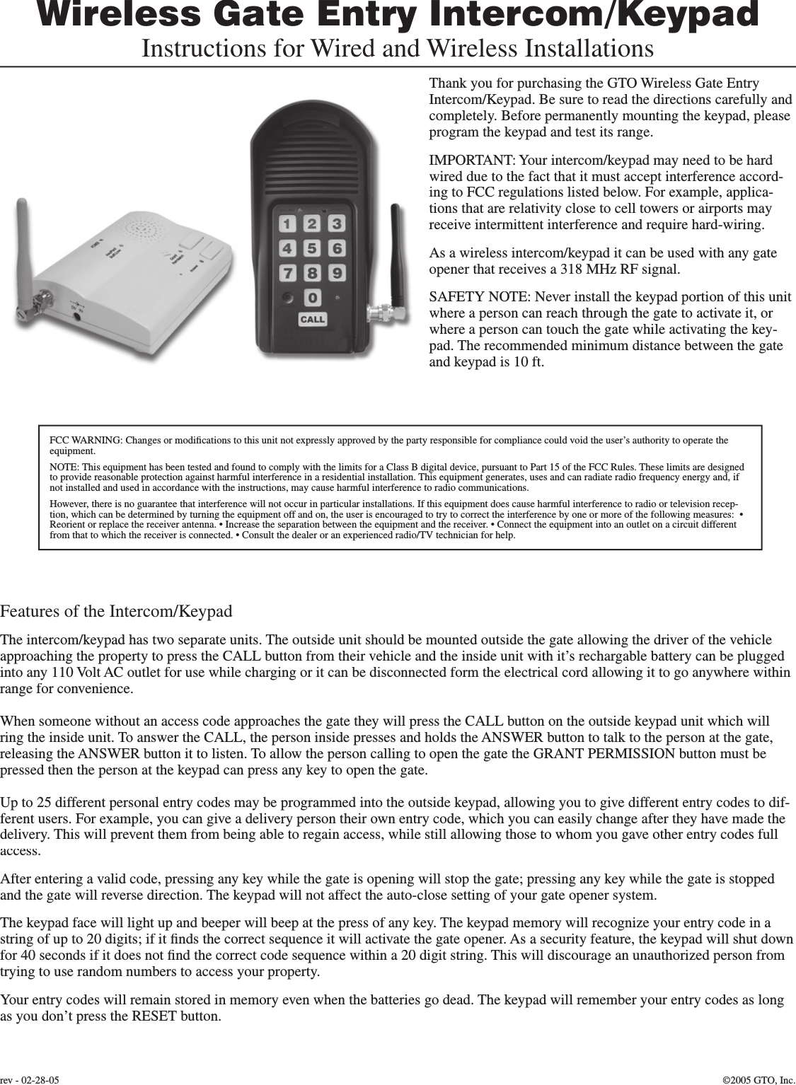
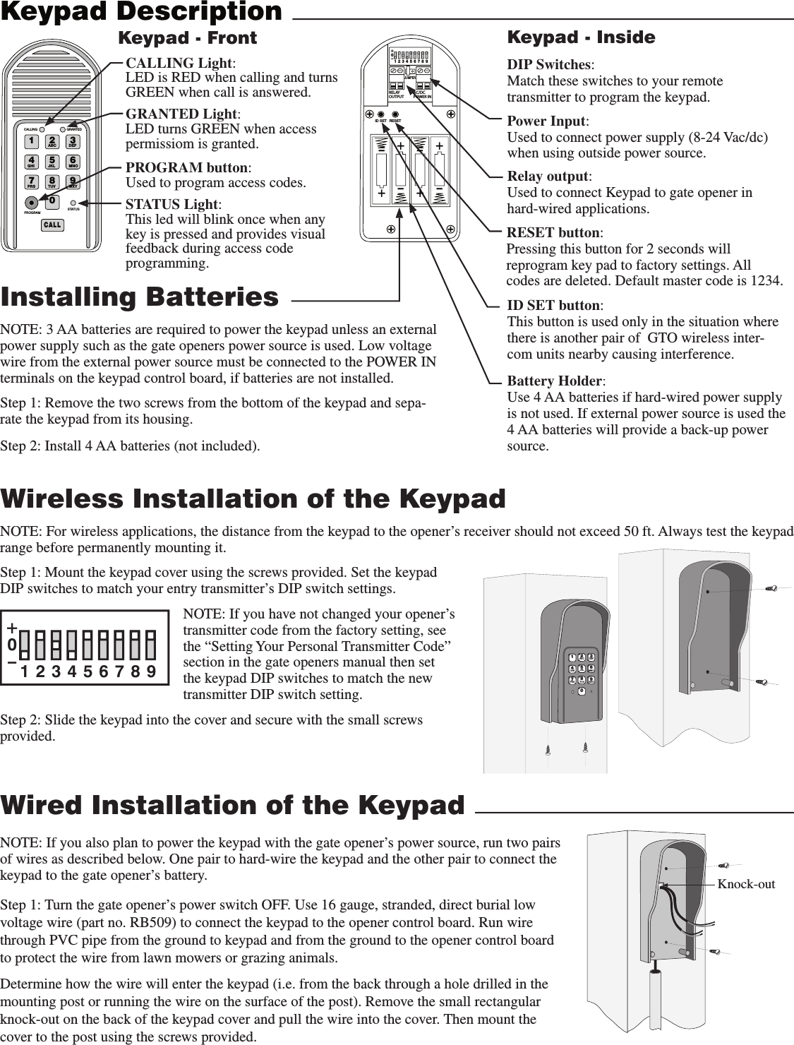
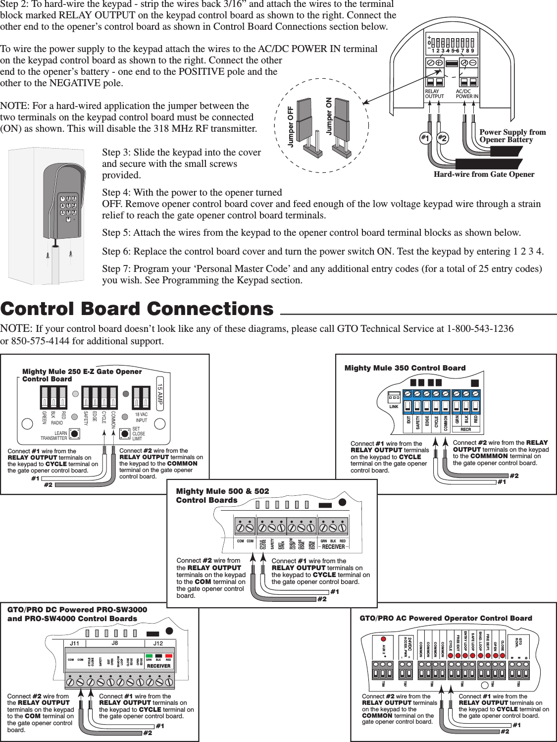
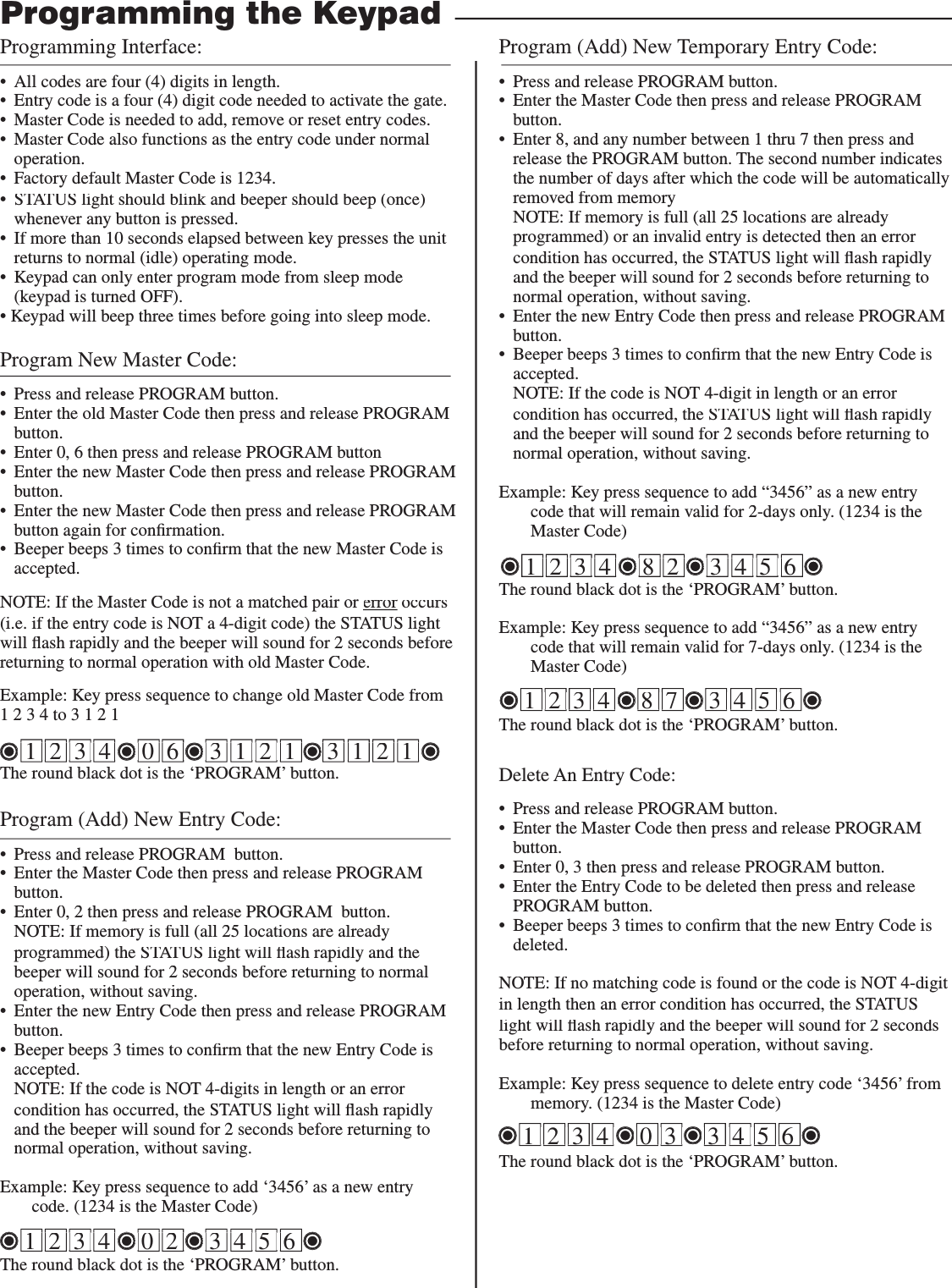
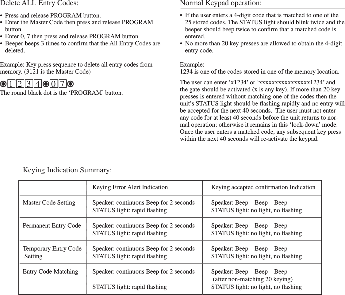
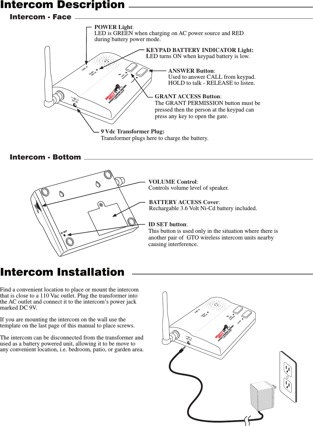
Smart Technologies and Investment SMARTECRF1252R 900MHz Transceiver of Intercom Unit User Manual New Intercom Instrs indd

Smart Technologies & Investment Ltd 900MHz Transceiver of Intercom Unit New Intercom Instrs indd

User Manual

Thank you for purchasing the GTO Wireless Gate Entry Intercom/Keypad. Be sure to read the directions carefully and completely. Before permanently mounting the keypad, please program the keypad and test its range.IMPORTANT: Your intercom/keypad may need to be hard wired due to the fact that it must accept interference accord-ing to FCC regulations listed below. For example, applica-tions that are relativity close to cell towers or airports may receive intermittent interference and require hard-wiring.As a wireless intercom/keypad it can be used with any gate opener that receives a 318 MHz RF signal. SAFETY NOTE: Never install the keypad portion of this unit where a person can reach through the gate to activate it, or where a person can touch the gate while activating the key-pad. The recommended minimum distance between the gate and keypad is 10 ft.Wireless Gate Entry Intercom/KeypadInstructions for Wired and Wireless InstallationsFeatures of the Intercom/KeypadThe intercom/keypad has two separate units. The outside unit should be mounted outside the gate allowing the driver of the vehicle approaching the property to press the CALL button from their vehicle and the inside unit with it’s rechargable battery can be plugged into any 110 Volt AC outlet for use while charging or it can be disconnected form the electrical cord allowing it to go anywhere within range for convenience. When someone without an access code approaches the gate they will press the CALL button on the outside keypad unit which will ring the inside unit. To answer the CALL, the person inside presses and holds the ANSWER button to talk to the person at the gate, releasing the ANSWER button it to listen. To allow the person calling to open the gate the GRANT PERMISSION button must be pressed then the person at the keypad can press any key to open the gate.Up to 25 different personal entry codes may be programmed into the outside keypad, allowing you to give different entry codes to dif-ferent users. For example, you can give a delivery person their own entry code, which you can easily change after they have made the delivery. This will prevent them from being able to regain access, while still allowing those to whom you gave other entry codes full access.After entering a valid code, pressing any key while the gate is opening will stop the gate; pressing any key while the gate is stopped and the gate will reverse direction. The keypad will not affect the auto-close setting of your gate opener system.The keypad face will light up and beeper will beep at the press of any key. The keypad memory will recognize your entry code in a string of up to 20 digits; if it fi nds the correct sequence it will activate the gate opener. As a security feature, the keypad will shut down for 40 seconds if it does not fi nd the correct code sequence within a 20 digit string. This will discourage an unauthorized person from trying to use random numbers to access your property.Your entry codes will remain stored in memory even when the batteries go dead. The keypad will remember your entry codes as long as you don’t press the RESET button.©2005 GTO, Inc.rev - 02-28-05FCC WARNING: Changes or modifi cations to this unit not expressly approved by the party responsible for compliance could void the user’s authority to operate the equipment.NOTE: This equipment has been tested and found to comply with the limits for a Class B digital device, pursuant to Part 15 of the FCC Rules. These limits are designed to provide reasonable protection against harmful interference in a residential installation. This equipment generates, uses and can radiate radio frequency energy and, if not installed and used in accordance with the instructions, may cause harmful interference to radio communications. However, there is no guarantee that interference will not occur in particular installations. If this equipment does cause harmful interference to radio or television recep-tion, which can be determined by turning the equipment off and on, the user is encouraged to try to correct the interference by one or more of the following measures:  • Reorient or replace the receiver antenna. • Increase the separation between the equipment and the receiver. • Connect the equipment into an outlet on a circuit different from that to which the receiver is connected. • Consult the dealer or an experienced radio/TV technician for help.
Wired Installation of the KeypadNOTE: If you also plan to power the keypad with the gate opener’s power source, run two pairs of wires as described below. One pair to hard-wire the keypad and the other pair to connect the keypad to the gate opener’s battery.Step 1: Turn the gate opener’s power switch OFF. Use 16 gauge, stranded, direct burial low voltage wire (part no. RB509) to connect the keypad to the opener control board. Run wire through PVC pipe from the ground to keypad and from the ground to the opener control board to protect the wire from lawn mowers or grazing animals.Determine how the wire will enter the keypad (i.e. from the back through a hole drilled in the mounting post or running the wire on the surface of the post). Remove the small rectangular knock-out on the back of the keypad cover and pull the wire into the cover. Then mount the cover to the post using the screws provided.Keypad DescriptionInstalling BatteriesNOTE: 3 AA batteries are required to power the keypad unless an external power supply such as the gate openers power source is used. Low voltage wire from the external power source must be connected to the POWER IN terminals on the keypad control board, if batteries are not installed.    Step 1: Remove the two screws from the bottom of the keypad and sepa-rate the keypad from its housing.Step 2: Install 4 AA batteries (not included).        STATUS Light:This led will blink once when any key is pressed and provides visual feedback during access code programming.GRANTED Light:LED turns GREEN when access permissiom is granted.Keypad - FrontBattery Holder:Use 4 AA batteries if hard-wired power supply is not used. If external power source is used the 4 AA batteries will provide a back-up power source. ID SET button:This button is used only in the situation where there is another pair of  GTO wireless inter-com units nearby causing interference. DIP Switches:Match these switches to your remote transmitter to program the keypad.Relay output:Used to connect Keypad to gate opener in hard-wired applications.Power Input:Used to connect power supply (8-24 Vac/dc) when using outside power source.Keypad - InsideKnock-outWireless Installation of the KeypadNOTE: For wireless applications, the distance from the keypad to the opener’s receiver should not exceed 50 ft. Always test the keypad range before permanently mounting it.Step 1: Mount the keypad cover using the screws provided. Set the keypad DIP switches to match your entry transmitter’s DIP switch settings. NOTE: If you have not changed your opener’s transmitter code from the factory setting, see the “Setting Your Personal Transmitter Code” section in the gate openers manual then set the keypad DIP switches to match the new transmitter DIP switch setting.Step 2: Slide the keypad into the cover and secure with the small screws provided. 12ABC3DEF4GHI5JKL6MNO7PRS8TUV9WXY0123456789+0–PROGRAM button:Used to program access codes.CALLING Light:LED is RED when calling and turns GREEN when call is answered.RESET button:Pressing this button for 2 seconds will reprogram key pad to factory settings. All codes are deleted. Default master code is 1234.
RELAYOUTPUTAC/DCPOWER IN123456789+0–Jumper ONJumper OFFHard-wire from Gate OpenerPower Supply from Opener Battery#1#2Step 2: To hard-wire the keypad - strip the wires back 3/16” and attach the wires to the terminal block marked RELAY OUTPUT on the keypad control board as shown to the right. Connect the other end to the opener’s control board as shown in Control Board Connections section below.To wire the power supply to the keypad attach the wires to the AC/DC POWER IN terminal on the keypad control board as shown to the right. Connect the other end to the opener’s battery - one end to the POSITIVE pole and the other to the NEGATIVE pole.NOTE: For a hard-wired application the jumper between the two terminals on the keypad control board must be connected (ON) as shown. This will disable the 318 MHz RF transmitter. Step 3: Slide the keypad into the cover and secure with the small screws provided.Step 4: With the power to the opener turned OFF. Remove opener control board cover and feed enough of the low voltage keypad wire through a strain relief to reach the gate opener control board terminals.Step 5: Attach the wires from the keypad to the opener control board terminal blocks as shown below.Step 6: Replace the control board cover and turn the power switch ON. Test the keypad by entering 1 2 3 4.Step 7: Program your ‘Personal Master Code’ and any additional entry codes (for a total of 25 entry codes) you wish. See Programming the Keypad section. Control Board Connections12ABC3DEF4GHI5JKL6MNO7PRS8TUV9WXY0EDGEREDBLKGREENSAFETYCYCLERADIO18 VACINPUTLEARNTRANSMITTERSETCLOSELIMITCOMMON15 AMPConnect #1 wire from the RELAY OUTPUT terminals on the keypad to CYCLE terminal on the gate opener control board.Connect #2 wire from the RELAY OUTPUT terminals on the keypad to the COMMON terminal on the gate opener control board.Mighty Mule 250 E-Z Gate OpenerControl Board#1#2GRN BLK REDRECEIVERCOM COMCYCLECLOSECYCLECLOSESAFETYEXITOPENSHADOWLOOPCLOSE EDGEOPENEDGEJ11J11 J8 J12GTO/PRO DC Powered PRO-SW3000 and PRO-SW4000 Control BoardsConnect #1 wire from the RELAY OUTPUT terminals on the keypad to CYCLE terminal on the gate opener control board.Connect #2 wire from the RELAY OUTPUT terminals on the keypad to the COM terminal on the gate opener control board. #1#2NOTE: If your control board doesn’t look like any of these diagrams, please call GTO Technical Service at 1-800-543-1236 or 850-575-4144 for additional support.RECRGRNBLKREDEXITSAFETYEDGECYCLECOMMONLINKMighty Mule 350 Control BoardConnect #1 wire from the RELAY OUTPUT terminals on the keypad to CYCLE terminal on the gate opener control board.Connect #2 wire from the RELAY OUTPUT terminals on the keypad to the COMMMON terminal on the gate opener control board.#1#2+–GRBGTORCVR.CLOSEOPENFIRE DEPT.SHAD. LOOPSAFE LOOPENTRY LOOPFREE EXITCYCLECOMMONCOMMONCOMMONCOMMONAUX 2ACCES. PWR24VDCTB8TB7TB6TB5TB4TB3GTO/PRO AC Powered Operator Control BoardConnect #1 wire from the RELAY OUTPUT terminals on the keypad to CYCLE terminal on the gate opener control board.Connect #2 wire from the RELAY OUTPUT terminals on the keypad to the COMMON terminal on the gate opener control board. #1#2RECEIVERCOM COMCYCLECLOSESAFETYEXIT/OPENSHADOWLOOPCLOSEEDGEOPENEDGEBLKGRN REDMighty Mule 500 & 502 Control BoardsConnect #1 wire from the RELAY OUTPUT terminals on the keypad to CYCLE terminal on the gate opener control board.Connect #2 wire from the RELAY OUTPUT terminals on the keypad to the COM terminal on the gate opener control board. #1#2
Programming Interface:•  All codes are four (4) digits in length.•  Entry code is a four (4) digit code needed to activate the gate.•  Master Code is needed to add, remove or reset entry codes.•  Master Code also functions as the entry code under normal operation.•  Factory default Master Code is 1234.•  STATUS light should blink and beeper should beep (once) STATUS light should blink and beeper should beep (once) STATUS lightwhenever any button is pressed. •  If more than 10 seconds elapsed between key presses the unit returns to normal (idle) operating mode.•  Keypad can only enter program mode from sleep mode (keypad is turned OFF). • Keypad will beep three times before going into sleep mode.Program New Master Code:•  Press and release PROGRAM button. •  Enter the old Master Code then press and release PROGRAM button.•  Enter 0, 6 then press and release PROGRAM button•  Enter the new Master Code then press and release PROGRAM button.•  Enter the new Master Code then press and release PROGRAM button again for confi rmation. •  Beeper beeps 3 times to confi rm that the new Master Code is accepted.NOTE: If the Master Code is not a matched pair or error occurs error occurs error(i.e. if the entry code is NOT a 4-digit code) the STATUS lightwill fl ash rapidly and the beeper will sound for 2 seconds before returning to normal operation with old Master Code.Example: Key press sequence to change old Master Code from 1 2 3 4 to 3 1 2 1    1  2  3  4     0  6     3  1  2  1     3  1  2  1   The round black dot is the ‘PROGRAM’ button.Program (Add) New Entry Code:•  Press and release PROGRAM  button. •  Enter the Master Code then press and release PROGRAM  button.•  Enter 0, 2 then press and release PROGRAM  button.  NOTE: If memory is full (all 25 locations are already programmed) the STATUS light will fl ash rapidly and the STATUS light will fl ash rapidly and the STATUS lightbeeper will sound for 2 seconds before returning to normal operation, without saving.•  Enter the new Entry Code then press and release PROGRAM button.•  Beeper beeps 3 times to confi rm that the new Entry Code is accepted.  NOTE: If the code is NOT 4-digits in length or an error condition has occurred, the STATUS light will fl ash rapidly STATUS light will fl ash rapidly STATUS lightand the beeper will sound for 2 seconds before returning to normal operation, without saving.Example: Key press sequence to add ‘3456’ as a new entry code. (1234 is the Master Code)The round black dot is the ‘PROGRAM’ button.Program (Add) New Temporary Entry Code:•  Press and release PROGRAM button. •  Enter the Master Code then press and release PROGRAM button.•  Enter 8, and any number between 1 thru 7 then press and release the PROGRAM button. The second number indicates the number of days after which the code will be automatically removed from memory  NOTE: If memory is full (all 25 locations are already programmed) or an invalid entry is detected then an error condition has occurred, the STATUS light will fl ash rapidly STATUS light will fl ash rapidly STATUS lightand the beeper will sound for 2 seconds before returning to normal operation, without saving.•  Enter the new Entry Code then press and release PROGRAM button.•  Beeper beeps 3 times to confi rm that the new Entry Code is accepted.   NOTE: If the code is NOT 4-digit in length or an error condition has occurred, the STATUS light will fl ash rapidly STATUS light will fl ash rapidly STATUS lightand the beeper will sound for 2 seconds before returning to normal operation, without saving.Example: Key press sequence to add “3456” as a new entry code that will remain valid for 2-days only. (1234 is the Master Code)The round black dot is the ‘PROGRAM’ button.Example: Key press sequence to add “3456” as a new entry code that will remain valid for 7-days only. (1234 is the Master Code)The round black dot is the ‘PROGRAM’ button.Programming the KeypadDelete An Entry Code:•  Press and release PROGRAM button. •  Enter the Master Code then press and release PROGRAM button.•  Enter 0, 3 then press and release PROGRAM button.•  Enter the Entry Code to be deleted then press and release PROGRAM button.•  Beeper beeps 3 times to confi rm that the new Entry Code is deleted.NOTE: If no matching code is found or the code is NOT 4-digit in length then an error condition has occurred, the STATUS light will fl ash rapidly and the beeper will sound for 2 seconds light will fl ash rapidly and the beeper will sound for 2 seconds lightbefore returning to normal operation, without saving.   Example: Key press sequence to delete entry code ‘3456’ from memory. (1234 is the Master Code)The round black dot is the ‘PROGRAM’ button.    1  2  3  4     0  6     3  1  2  1     3  1  2  1       1  2  3  4     0  6     3  1  2  1     3  1  2  1       1  2  3  4     0  6     3  1  2  1     3  1  2  1       1  2  3  4     0  6     3  1  2  1     3  1  2  1       1  2  3  4     0  6     3  1  2  1     3  1  2  1       1  2  3  4     0  6     3  1  2  1     3  1  2  1       1  2  3  4     0  6     3  1  2  1     3  1  2  1       1  2  3  4     0  6     3  1  2  1     3  1  2  1       1  2  3  4     0  6     3  1  2  1     3  1  2  1       1  2  3  4     0  6     3  1  2  1     3  1  2  1       1  2  3  4     0  6     3  1  2  1     3  1  2  1       1  2  3  4     0  6     3  1  2  1     3  1  2  1       1  2  3  4     0  6     3  1  2  1     3  1  2  1       1  2  3  4     0  6     3  1  2  1     3  1  2  1       1  2  3  4     0  6     3  1  2  1     3  1  2  1       1  2  3  4     0  6     3  1  2  1     3  1  2  1       1  2  3  4     0  6     3  1  2  1     3  1  2  1       1  2  3  4     0  6     3  1  2  1     3  1  2  1       1  2  3  4     0  6     3  1  2  1     3  1  2  1       1  2  3  4     0  6     3  1  2  1     3  1  2  1       1  2  3  4     0  6     3  1  2  1     3  1  2  1       1  2  3  4     0  6     3  1  2  1     3  1  2  1       1  2  3  4     0  6     3  1  2  1     3  1  2  1       1  2  3  4     0  6     3  1  2  1     3  1  2  1       1  2  3  4     0  6     3  1  2  1     3  1  2  1       1  2  3  4     0  6     3  1  2  1     3  1  2  1       1  2  3  4     0  6     3  1  2  1     3  1  2  1       1  2  3  4     0  6     3  1  2  1     3  1  2  1       1  2  3  4     0  6     3  1  2  1     3  1  2  1       1  2  3  4     0  6     3  1  2  1     3  1  2  1       1  2  3  4     0  6     3  1  2  1     3  1  2  1       1  2  3  4     0  6     3  1  2  1     3  1  2  1       1  2  3  4     0  6     3  1  2  1     3  1  2  1       1  2  3  4     0  6     3  1  2  1     3  1  2  1   1  2  3  4     0  2     3  4  5  6 1  2  3  4     0  2     3  4  5  6 1  2  3  4     0  2     3  4  5  6 1  2  3  4     0  2     3  4  5  6 1  2  3  4     0  2     3  4  5  6 1  2  3  4     0  2     3  4  5  6 1  2  3  4     0  2     3  4  5  6 1  2  3  4     0  2     3  4  5  6 1  2  3  4     0  2     3  4  5  6 1  2  3  4     0  2     3  4  5  6 1  2  3  4     0  2     3  4  5  6 1  2  3  4     0  2     3  4  5  6 1  2  3  4     0  2     3  4  5  6 1  2  3  4     0  2     3  4  5  6 1  2  3  4     0  2     3  4  5  6 1  2  3  4     0  2     3  4  5  6 1  2  3  4     0  2     3  4  5  6 1  2  3  4     0  2     3  4  5  6 1  2  3  4     0  2     3  4  5  6 1  2  3  4     8  2     3  4  5  6 1  2  3  4     8  2     3  4  5  6 1  2  3  4     8  2     3  4  5  6 1  2  3  4     8  2     3  4  5  6 1  2  3  4     8  2     3  4  5  6 1  2  3  4     8  2     3  4  5  6 1  2  3  4     8  2     3  4  5  6 1  2  3  4     8  2     3  4  5  6 1  2  3  4     8  2     3  4  5  6 1  2  3  4     8  2     3  4  5  6 1  2  3  4     8  2     3  4  5  6 1  2  3  4     8  2     3  4  5  6 1  2  3  4     8  2     3  4  5  6 1  2  3  4     8  2     3  4  5  6 1  2  3  4     8  2     3  4  5  6 1  2  3  4     8  2     3  4  5  6 1  2  3  4     8  2     3  4  5  6 1  2  3  4     8  2     3  4  5  6 1  2  3  4     8  2     3  4  5  6 1  2  3  4     0  3     3  4  5  6 1  2  3  4     0  3     3  4  5  6 1  2  3  4     0  3     3  4  5  6 1  2  3  4     0  3     3  4  5  6 1  2  3  4     0  3     3  4  5  6 1  2  3  4     0  3     3  4  5  6 1  2  3  4     0  3     3  4  5  6 1  2  3  4     0  3     3  4  5  6 1  2  3  4     0  3     3  4  5  6 1  2  3  4     0  3     3  4  5  6 1  2  3  4     0  3     3  4  5  6 1  2  3  4     0  3     3  4  5  6 1  2  3  4     0  3     3  4  5  6 1  2  3  4     0  3     3  4  5  6 1  2  3  4     0  3     3  4  5  6 1  2  3  4     0  3     3  4  5  6 1  2  3  4     0  3     3  4  5  6 1  2  3  4     0  3     3  4  5  6 1  2  3  4     0  3     3  4  5  6 1  2  3  4     8  7     3  4  5  6 1  2  3  4     8  7     3  4  5  6 1  2  3  4     8  7     3  4  5  6 1  2  3  4     8  7     3  4  5  6 1  2  3  4     8  7     3  4  5  6 1  2  3  4     8  7     3  4  5  6 1  2  3  4     8  7     3  4  5  6 1  2  3  4     8  7     3  4  5  6 1  2  3  4     8  7     3  4  5  6 1  2  3  4     8  7     3  4  5  6 1  2  3  4     8  7     3  4  5  6 1  2  3  4     8  7     3  4  5  6 1  2  3  4     8  7     3  4  5  6 1  2  3  4     8  7     3  4  5  6 1  2  3  4     8  7     3  4  5  6 1  2  3  4     8  7     3  4  5  6 1  2  3  4     8  7     3  4  5  6 1  2  3  4     8  7     3  4  5  6 1  2  3  4     8  7     3  4  5  6
Normal Keypad operation:•  If the user enters a 4-digit code that is matched to one of the 25 stored codes. The STATUS light should blink twice and the beeper should beep twice to confi rm that a matched code is entered. •  No more than 20 key presses are allowed to obtain the 4-digit entry code. Example: 1234 is one of the codes stored in one of the memory location. The user can enter ‘x1234’ or ‘xxxxxxxxxxxxxxxx1234’ and the gate should be activated (x is any key). If more than 20 key presses is entered without matching one of the codes then the unit’s STATUS light should be fl ashing rapidly and no entry will be accepted for the next 40 seconds.  The user must not enter any code for at least 40 seconds before the unit returns to nor-mal operation; otherwise it remains in this ‘lock-down’ mode. Once the user enters a matched code, any subsequent key press within the next 40 seconds will re-activate the keypad.Delete ALL Entry Codes:•  Press and release PROGRAM button. •  Enter the Master Code then press and release PROGRAM button.•  Enter 0, 7 then press and release PROGRAM button.•  Beeper beeps 3 times to confi rm that the All Entry Codes are deleted.Example: Key press sequence to delete all entry codes from memory. (3121 is the Master Code)The round black dot is the ‘PROGRAM’ button.Keying Indication Summary:  Keying Error Alert Indication  Keying accepted confi rmation Indication  Keying Error Alert Indication  Keying accepted confi rmation Indication  Keying Error Alert Indication  Keying accepted confi rmation IndicationMaster Code Setting  Speaker: continuous Beep for 2 seconds  Speaker: Beep – Beep – BeepMaster Code Setting  Speaker: continuous Beep for 2 seconds  Speaker: Beep – Beep – BeepMaster Code Setting  Speaker: continuous Beep for 2 seconds  Speaker: Beep – Beep – Beep  STATUS light: rapid fl ashing   STATUS light: no light, no fl ashing  STATUS light: rapid fl ashing   STATUS light: no light, no fl ashing  STATUS light: rapid fl ashing   STATUS light: no light, no fl ashingPermanent Entry Code  Speaker: continuous Beep for 2 seconds  Speaker: Beep – Beep – BeepPermanent Entry Code  Speaker: continuous Beep for 2 seconds  Speaker: Beep – Beep – BeepPermanent Entry Code  Speaker: continuous Beep for 2 seconds  Speaker: Beep – Beep – Beep  STATUS light: rapid fl ashing  STATUS light: no light, no fl ashing  STATUS light: rapid fl ashing  STATUS light: no light, no fl ashing  STATUS light: rapid fl ashing  STATUS light: no light, no fl ashingTemporary Entry Code   Speaker: continuous Beep for 2 seconds  Speaker: Beep – Beep – BeepTemporary Entry Code   Speaker: continuous Beep for 2 seconds  Speaker: Beep – Beep – BeepTemporary Entry Code   Speaker: continuous Beep for 2 seconds  Speaker: Beep – Beep – Beep Setting   STATUS light: rapid fl ashing  STATUS light: no light, no fl ashing Setting   STATUS light: rapid fl ashing  STATUS light: no light, no fl ashing Setting   STATUS light: rapid fl ashing  STATUS light: no light, no fl ashingEntry Code Matching  Speaker: continuous Beep for 2 seconds  Speaker: Beep – Beep – BeepEntry Code Matching  Speaker: continuous Beep for 2 seconds  Speaker: Beep – Beep – BeepEntry Code Matching  Speaker: continuous Beep for 2 seconds  Speaker: Beep – Beep – Beep      (after non-matching 20 keying)        (after non-matching 20 keying)        (after non-matching 20 keying)    STATUS light: rapid fl ashing  STATUS light: no light, no fl ashing  STATUS light: rapid fl ashing  STATUS light: no light, no fl ashing  STATUS light: rapid fl ashing  STATUS light: no light, no fl ashing1  2  3  4     0  71  2  3  4     0  71  2  3  4     0  71  2  3  4     0  71  2  3  4     0  71  2  3  4     0  71  2  3  4     0  71  2  3  4     0  71  2  3  4     0  71  2  3  4     0  71  2  3  4     0  7
Intercom DescriptionGRANT ACCESS Button:The GRANT PERMISSION button must be pressed then the person at the keypad can press any key to open the gate.Intercom - FaceANSWER Button:Used to answer CALL from keypad.HOLD to talk - RELEASE to listen.POWERKeypadBatt LowGrantPermissionAnswerDV  9VACCESS CONTROL SYSTEMS1-800-543-4283POWER Light:LED is GREEN when charging on AC power source and RED during battery power mode.KEYPAD BATTERY INDICATOR Light:LED turns ON when keypad battery is low.r9 Vdc Transformer Plug:Transformer plugs here to charge the battery. ID SETVOLUMEIntercom - BottomBATTERY ACCESS Cover:Rechargable 3.6 Volt Ni-Cd battery included.VOLUME Control:Controls volume level of speaker.ID SET button:This button is used only in the situation where there is another pair of  GTO wireless intercom units nearby causing interference. Intercom InstallationPOWERKeypadBatt LowGrantPermissionAnswerDV  9VACCESS CONTROL SYSTEMS1-800-543-4283Find a convenient location to place or mount the intercom that is close to a 110 Vac outlet. Plug the transformer into the AC outlet and connect it to the intercom’s power jack marked DC 9V.If you are mounting the intercom on the wall use the template on the last page of this manual to place screws.The intercom can be disconnected from the transformer and used as a battery powered unit, allowing it to be move to any convenient location, i.e. bedroom, patio, or garden area.
Limited One Year WarrantyGTO, Inc. gate opener accessories are warranted by the manufacturer against defects in workmanship for a period of one (1) year from the date of purchase, provided recommended installation procedures have been followed.In the case of product failure due to defective material or manufacturer workmanship within the one (1) year warranty period, the accessory will be re-paired or replaced (at the manufacturer’s option) at no charge to the customer, if returned freight prepaid to GTO, Inc., 3121 Hartsfi eld Rd., Tallahassee, FL 32303. IMPORTANT: Call 850/575-4144 or fax 850/575-8950 for a Return Goods Authorization (RGA) number before returning goods to factory. Products received at the factory without an RGA will not be accepted. Replacement or repaired parts are covered by this warranty for the remainder of the one (1) year warranty period. GTO, Inc. will pay the shipping charges for return to the owner of items repaired.The manufacturer will not be responsible for any charges or damages incurred in the removal of the defective parts for repair, or for the reinstallation of those parts after repair. This warranty shall be considered void if damage to the product(s) was due to improper installation or use, connection to an improper power source, tampering, or if damage was caused by lightning, wind, fi re, fl ood, insects, or other natural agent.After the one (1) year warranty period, GTO Inc. or one of its authorized service centers will make any necessary repairs for a nominal fee. Call GTO at 850/575-4144  for more information. This warranty gives you specifi c legal rights, and you may also have other rights which may vary from state to state. This warranty is in lieu of all other warranties, expressed or implied. NOTE: Verifi cation of the warranty period requires copies of receipts or other proof of purchase. Please retain those records.If you have any questions or concerns, please contact our Technical Service Department at 1-800-543-1236 or 850-575-4144.GTO, Inc. • 3121 Hartsfi eld Road • Tallahassee, Florida 32303Telephone (850) 575-0176 • Fax (850) 575-8912 • website www.gtoinc.comThe contents of all material available on this installation manual are copyrighted by GTO, Inc. (“GTO”), unless otherwise indicated. All rights are reserved by GTO, and content may not be reproduced, downloaded, disseminated, published, or transferred in any form or by any means, except with the prior, written permission of GTO.  Any reprinting of GTO publications is by permission only. Copyright infringement is a violation of federal law. GTO®, GTO/PRO®, Mighty Mule® are registered trademarks of GTO, Inc. Professional Access Systems™ is a trademark of GTO, Inc. and are the exclusive property of GTO, Inc. (“GTO”).  All rights are reserved by GTO, and these marks may not be used, in any for without the prior, written permission of GTO.  Testing the SystemHave someone press the CALL button on the Keypad at the gate. When the Intercom inside the house rings press press the ANSWER button and talk to the person at the gate to check the connectiion and range. Then press the GRANT PERMISSION button and have the person at the gate press any key to open the gate.NOTE: If any key is pressed while the gate is opening will cause the to stop and pressing any key again will allow the gate to continue to open.Hole Template for Mounting the Intercom

Navigation menu