Smart Technologies and Investment SMARTECSD2707 Wireless Wand KIT User Manual
Smart Technologies & Investment Ltd Wireless Wand KIT
User Manual
GTO Wireless Exit Sensor
INSTALLATION MANUAL
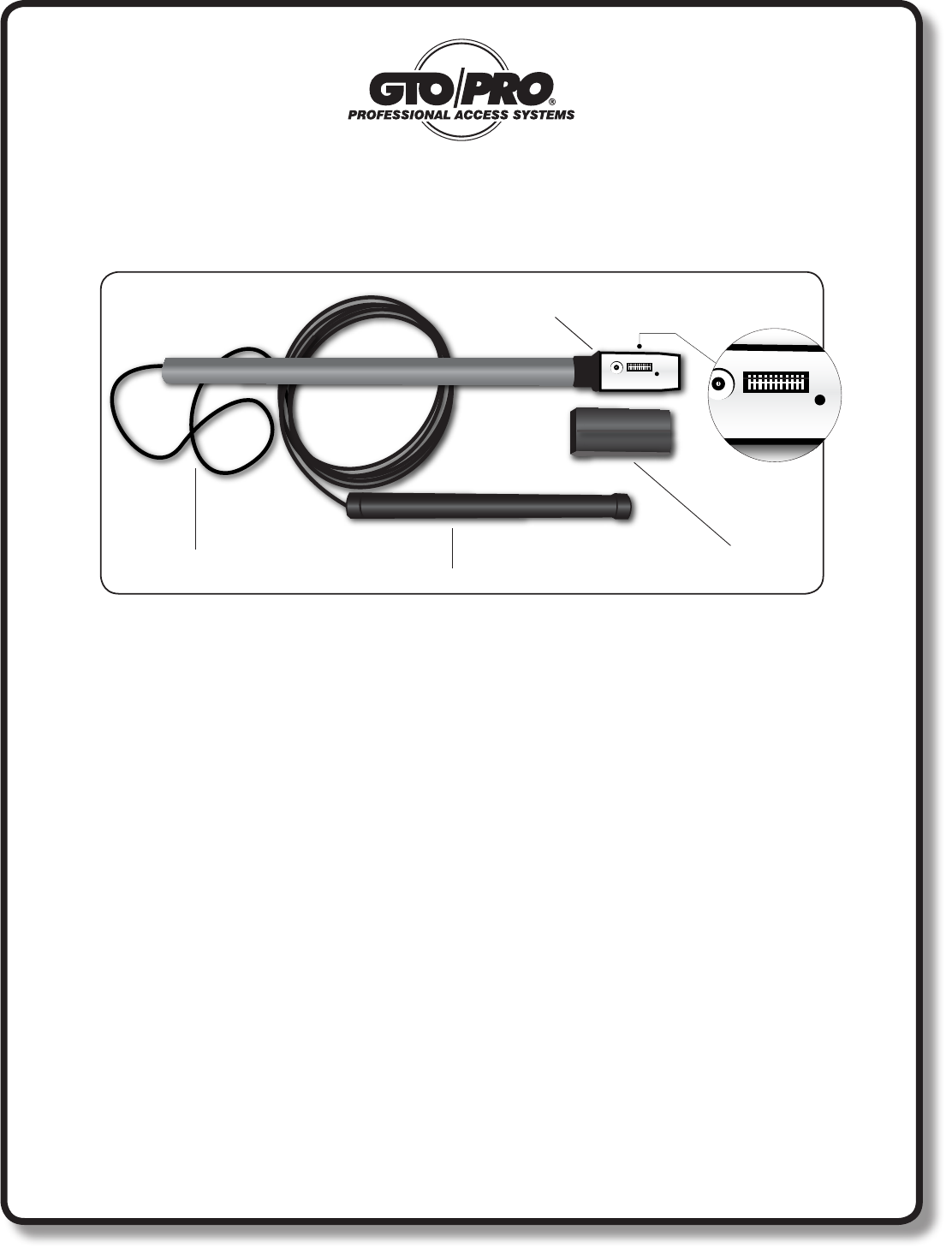
Kit Includes:
• Wirelessvehiclesensorwithdirectburialcoilassemblyandaplug-inelectronics/transmitter
moduledesignedformountingupto15feetawayfromthepavementedge.
• RB709U-NBtwochannelreceiverwithinstructions.
• TwosizeAAbatteries.
• GTOWirelessExitSensorinstructionmanualforgeneralinstallationguidance.
Rev.01/21/08•PrintedinChinaforGTO,Inc.
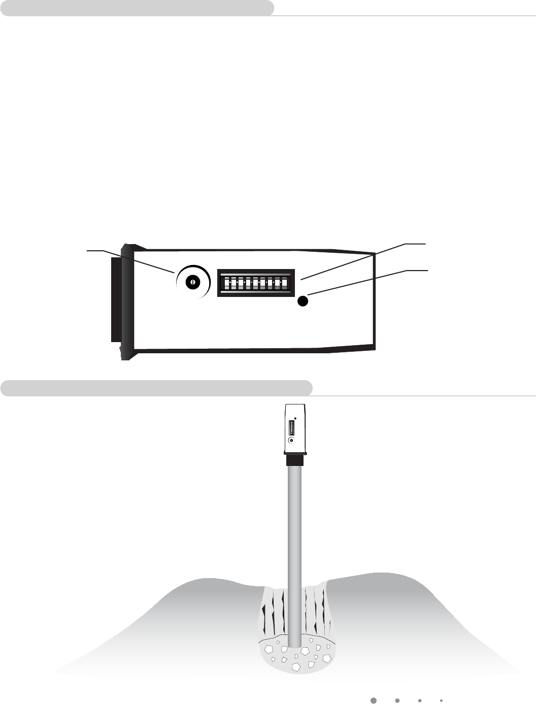
Signal Cable
Vehicle Sensor
Module Cover
Electronics/Transmitter
Module
Programmable
Dip Switches
How it works:
TheGTOwirelessexitsensorconsistsofavehiclesensor,transmitter,andprogrammabledipswitches.
Themaximumrangebetweentransmitterandreceiveris80-100ft.
ThetransmittermoduletransmitsaspecialGTOtransmittercodewithadditionalinformationtotellthereceiver
thatthisdeviceshouldbetreatedasa“freeexit”device.ThelatestGTOgateoperatorswithbluecontrolboards
(GTO“GEN3”)areabletodecodethisformatandrecognizethedeviceasafreeexitoropenonlycommand
withouttheuseoftheRB709U-NBreceiver.Thiswillsimplifyinstallationssoonlytheoriginalreceiverwillbe
required.
TheRB709U-NBreceiverwillberequiredunlessyouhavetheGEN3(blueboard).TheRB-709U-NBhastwo
channelsthatcanbeprogrammedtooperatearemotetransmitterorkeypadandwirelesswand.Forinstance,
Channel1couldbewiredtotheCycleandCOMaccessoryterminalsandcouldbeprogrammedtooperatea
transmitterandkeypad.Channel2couldbewiredtotheExitandCOMaccessoryterminalsandcouldbeused
tooperatethewirelessexitsensor.Dependingonthefrequencyofuse(vehicletrafc)thetwoAAbatterieswill
lastabout1to3years.
Thank you for purchasing the GTO Wireless Exit Sensor. Please read the directions carefully and completely before installing.
For more information on GTO's full line of automatic gate openers and access controls visit our website at www.gtoaccess.com
GTO WIRELESS EXIT WAND
TRANSMITTER
CODE TRANSMIT
ACTIVE
MIN MAX
SENSITIVITY
GTO WIRELESS EXIT WAND
TRANSMITTER
CODE TRANSMIT
ACTIVE
MIN MAX
SENSITIVITY
2
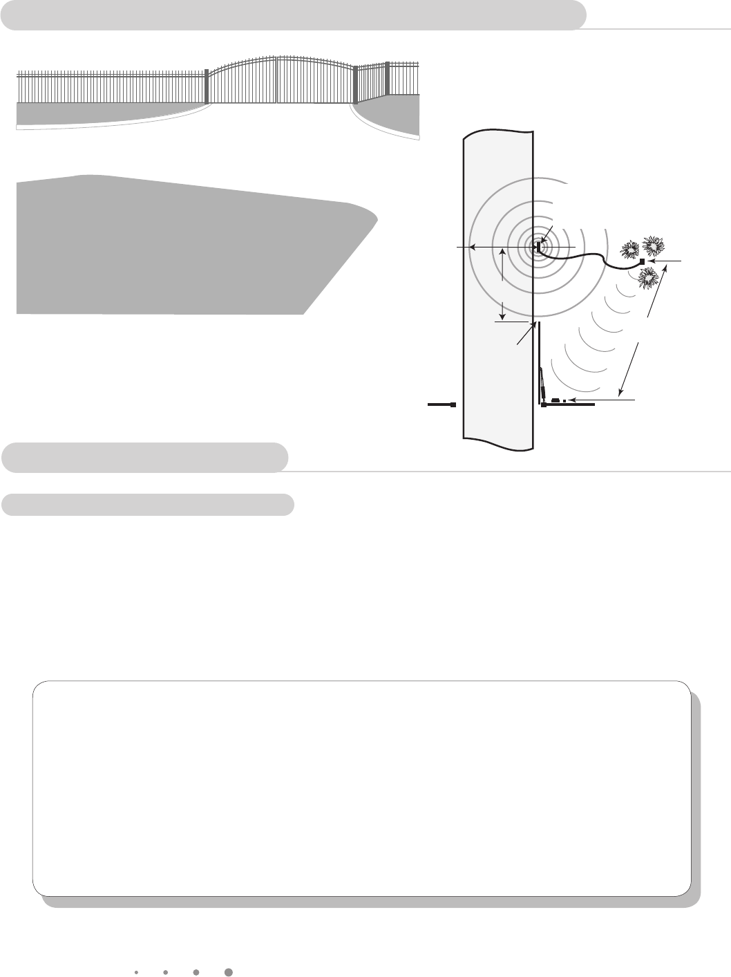
Wireless Exit Sensor
Above is a typical location where installing a conventional
“wired” exit sensor would require cutting and trenching
across more than 50 feet of asphalt driveway.
Gate Opener
Receiver
Driveway
Transmitter
100’ Max
Wireless
RANGE:
12 ft. radius
(max)
SENSOR:
2 feet from
driveway (max)
and 12” deep
Open Gate
Outside
Sensor Range
25 ft. from
gate (min)
Sensor and Module Placement Overview
• DeterminetheoptimumlocationfortheVEHICLESENSORusingtheinformationfoundabovein“Sensorand
TransmitterPlacementOverview”.Thendigaholeapproximately10-12inchesdeepand24incheslongwithin
2feetandparalleltotheedgeofthedriveway.Next,digatrenchnomorethan15ftfromthisholetothelocation
whereyouwillinstallthetransmittermodule.KeeptheVEHICLESENSORandthecableuncoveredatthistime.
IMPORTANT: Clear an area 20 feet in all directions of metal tools, toys and automobiles, to prevent magnetic disturbance
during testing and installation.
Sensor Placement
Determining Sensor Location
For Optimum Performance:
•LocatetheSENSORasfaraspossibleawayfrompowertransformers,powerlines,underground
gasline,andtelephonelines.
•LocatetheSENSORawayfromgeneralmovingtrafctopreventunwantedactivation.Remember
thattheSENSORdetectsMAGNETICDISTURBANCEScausedbyavehicle’smassandvelocity.
•Rangedistanceisapproximateandwillvaryduetooutsideinterference,typeofsoil,vehiclemass,
speed,etc.
•ItisrecommendedthatyouruntheSignalCableinsidePVCconduittopreventaccidentaldamage.
•DonotrunSignalCableinconduitwithotherwiressuchasACpowerorothercontrolwires.
•TheSIGNALCABLECANNOTBESPLICED.Ifyouneedmorewire,contacttheGTOSales
Departmentat1-800-543-GATE(4283).
NOTE: Place the transmitter on
the same side of the driveway in
the line of sight of the receiver to
maximize the range.
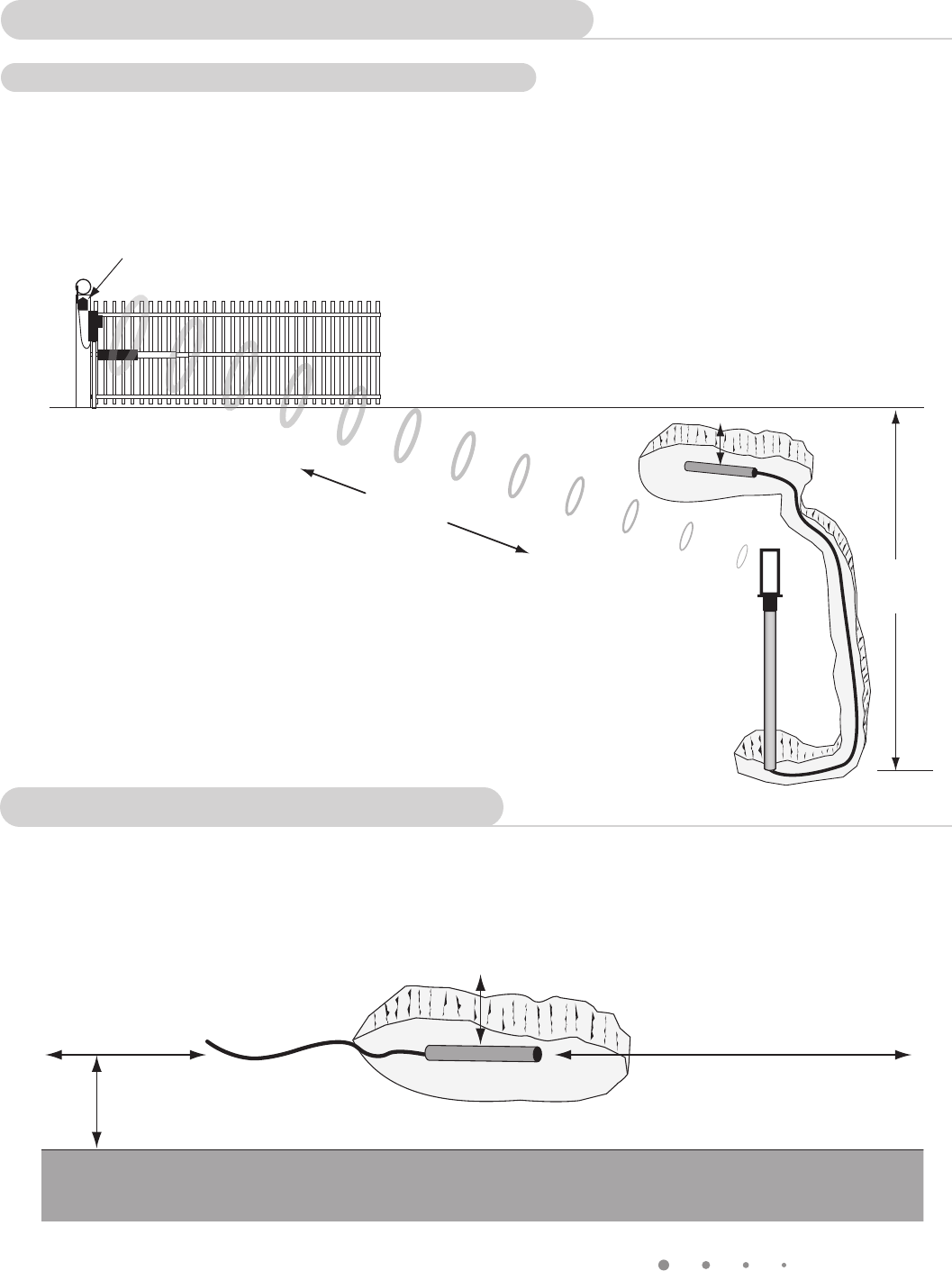
Wireless Exit Sensor
3
Receiver
Transmitter
Module
Driveway 10 -12 inch deep pit
15 ft
maximum
Vehicle Sensor
100 ft
Maximum
Install the Vehicle Sensor
DO NOT fill the hole until final testing is complete.
• Digasmallpitabout10-12inchesdeepclosetotheedgeofyourdriveway.Theholeshouldallowyoutolay
theVehicleSensoratinthebottomwiththelengthoftheVehicleSensorparalleltothedirectionofthedriveway.
• Afterlayingthevehiclesensorintheholeadjacent
tothedriveway.Runthesignalcabletothe
transmittermoduleinthenarrowtrench.
Do not fill the hole or trench until satisfactory
operation is verified.
Vehicle Sensor
10-12 inch
deep pit
Placed 2 ft maximum
from edge of driveway
Vehicle Sensor should
lay parallel to driveway
DRIVEWAY
Transmitter Module Placement
Determining Transmitter Module Location
• Choosealocationforthetransmittermodulethatisfarenoughfromthedrivewayedgethatvehiclesare
unlikelytohitit.Fifteenfeetofwireisincludedtoallowthetransmittertobe12to15feetfromthedriveway.
Totestthechosenlocationtobesureitisfreefromobstructionsorotherinterference,youcanuseyour
remotecontroltransmitteratthesameheightasthetransmittermoduletoactivatethegate.
4
Wireless Exit Sensor
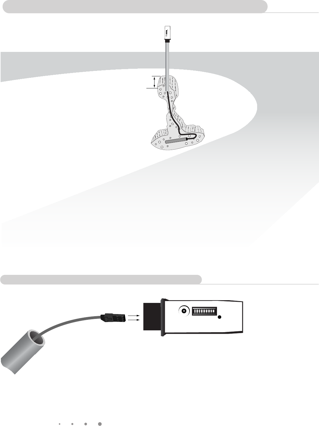
6 inches
deep
Sensor
NOTE: DO NOT place in the direct path of a sprinkler.
The module is water resistant but not waterproof.
• DiganarrowtrenchorslitfromtheVehicle
Sensortothetransmitterlocationusingaat
spadeorothertool.Thewirefromthewandto
thetransmittershouldbeatleastsixinches
deeptoavoidpossibledamagefromedgers,
orlawnaerators.
GTO WIRELESS EXIT WAND
TRANSMITTER
CODE
MED
TRANSMIT
ACTIVE
MIN MAX
SENSITIVITY
• FeedtheSignalCablethroughthePVCpipe
andplugintotheconnectoratthebottomof
theElectronics/Transmittermodule.
Connecting the Electronics/Transmitter Module
Install the Electronics/Transmitter Module
Wireless Exit Sensor
5
GTO WIRELESS EXIT WAND
TRANSMITTER
CODE
MED
TRANSMIT
ACTIVE
MIN MAX
SENSITIVITY
NOTE: The module should extend out
at least 12” above ground.
• InstallandconnecttheRB709U-NBreceivertoyourgateoperatorasshownintheinstructionssuppliedwith
thatreceiver.YoucanskipthisstepifyouhaveaGTOGEN3controlboardonyourgateoperator.
• IfusingtheRB709U-NBreceiver,itisrecommendedthatyoudisconnecttheoriginalantennareceiverthat
camewithyourgateopener.
• RemovetheoutercoverfromtheElectronics/TransmitterModule.
• SetthetransmitterDipSwitches.IfyouhaveGTOhandheldtransmittersforyourgate,settheDipSwitchesin
theTransmitter/ModuletothesamesettingsastheDipSwitchesinyourtransmitter.IfyoudonothaveGTO
transmitters,settheDipSwitchestoanydesiredsetting.Wedonotrecommendusingthefactorycode
settingasshipped.
• Setthesensitivitycontroltomidscale(mediumsensitivity).
• DONOTinstallthebatteriesatthistime!
GTO WIRELESS EXIT WAND
TRANSMITTER
CODE
MED
TRANSMIT
ACTIVE
MIN MAX
SENSITIVITY
Sensitivity
Potentiometer
Dip Switches
Transmit Indicator
• SecuretheElectronics/TransmitterModuleon
thesuppliedPVCpipebyburyingthebottomthird
ofthepipeinthesoilandtampingtheground
aroundthepipe.DONOTcovertheelectronics
modulewithametalcoverasthiswillcause
signalinterference.
• Thiscompletesthehardwareinstallation.
Electronics/Transmitter Module Setup
Planting the Electronics/Transmitter Module
6
Wireless Exit Sensor
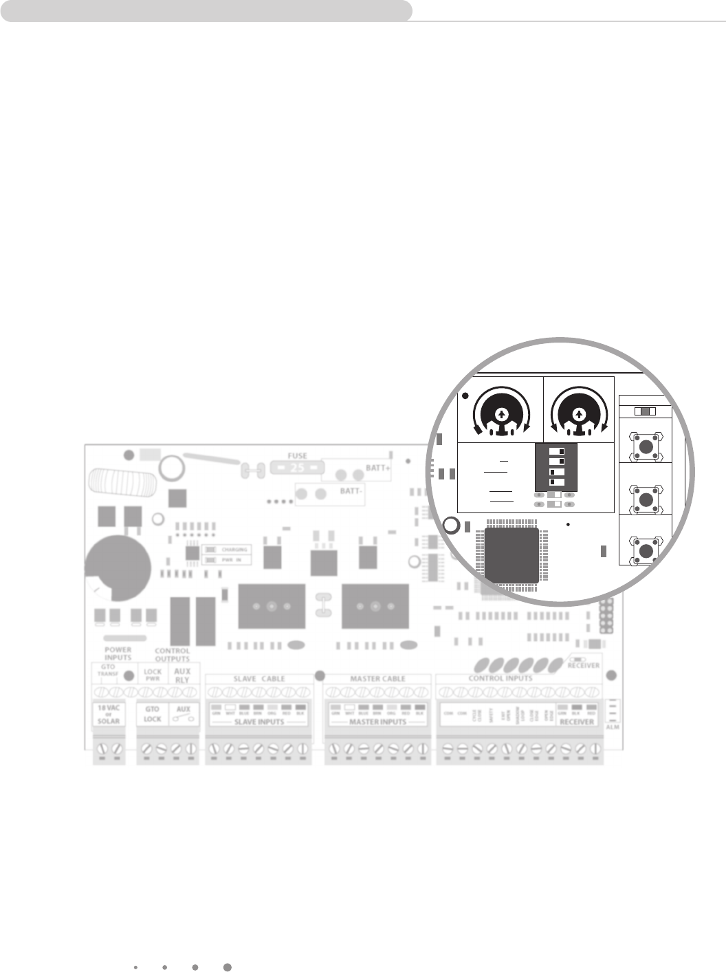
To use or not to use the Included Receiver
DependingonthetypeofcontrolboardyouareusingyoumayormaynotneedtousetheRB709U-NB
universal receiverincludedwiththeWirelessExitSensor.
• Post mount operators with a GEN-3 Blue Control Board DO NOT require that you use the RB709U-NB
universal receiver.
(SeethepicturesbelowtodetermineifyouhaveaGEN-3BlueControlBoard).
• ALL PAD MOUNT OPERATORS will require the use of the RB709U-NB universal receiver.
1 2 3 4
ON DIP
STATUS
LEARN RMT
LEARN
MAST LIMIT
LEARN
SLV LIMIT
S3
S4
S2
OFF
SOFT START OFF
WARNING OFF
OPEN PULL
SLV OPEN DLY.
MODE1 OFF
MODE2 OFF
ON
ON
PUSH
SIMULT.
ON
ON
120 MIN MAX
AUTO CLOSE TIME STALL FORCE
GEN-3 Blue Control Board
DOESNOTrequiretheRB709U-NBuniversalreceiver
Wireless Exit Sensor
7
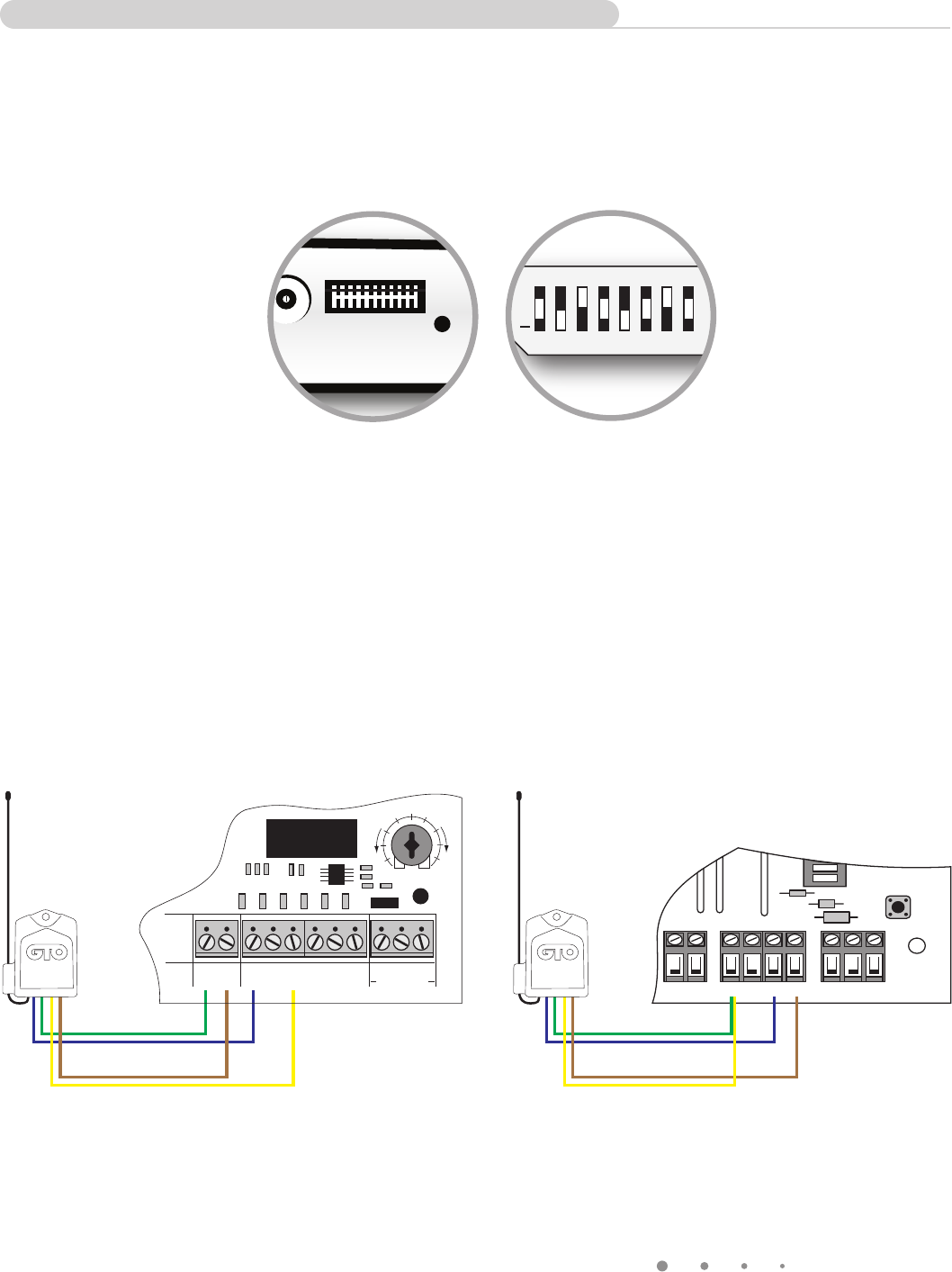
Programming the Exit Sensor’s Transmitter Code
Beforeuse,thereceiverneedsto“learn”thecodetransmittedbythewirelessexitsensor.Thissimpleprocedure
takesonlyafewminutes.
• Gen3(blueboard)instructions
Setthe9DipSwitchesintheTransmitterModuletothesamesettingsasthe9DipSwitchesinthe
GTORemoteTransmitter.TheGen3(blueboard)willautomaticallyrespondtothewirelessexitsensor’s
transmissionasafreeexitoropenonlycommand.
• ForoperatorsWITHOUTtheGen3(blueboard)
Disconnectthered,blackandgreenwiresfromtheoriginalreceiveratthereceiverterminalsonthegate
opener’scircuitboard.Itwillnolongerbeneeded.
WireChannel1(greenandbluewires)ontheRB709U-NBtotheCycleandCOMaccessoryterminalsonthe
gateopener.Holddownthegateopener’sremotetransmitterbuttonandtheChannel1buttonontheRB709U-
NBatthesametime.TheredlightontheRB709U-NBshouldblinkoncein1to2secondstoindicatethatthe
receiverhaslearnedthecodefromtheexitsensor.
WireChannel2(yellowandbrownwires)ontheRB709U-NBtotheExitandCOMterminalsonthegateopener.
InstallthetwoAAbatteriesinthewirelessexitsensor’stransmittermodule.Thiswillimmediatelystart30seconds
oftransmissionsfromthewirelessexitsensor.Whiletheexitsensoristransmitting,holddowntheChannel2
buttonontheRB709U-NB.TheredlightontheRB709U-NBshouldblinkoncein1to2secondstoindicatethat
thereceiverhaslearnedthecodefromtheexitsensor.
Transmitter Module
Dip Switches
SetSameAsGTORemote
TransmitterDipSwitches
Remote Transmitter
Dip Switches
SetSameAs
TransmitterModuleDipSwitches
PRO3040-PCB Connections GTO/PRO1000, SL1000/2000 Connections
ON
ALARM ACCESSORY RCVR
SEQ1
SEQ2
LEARN
BLU
ORG
WHT
GRN
R B G
CH 1 (Green Wire to Grn)
CH 1 (Blue Wire to Blu)
CH 2 (Yellow Wire to Grn)
CH 2 (Brown Wire to Wht)
CH 1 (Green Wire to Com)
CH 1 (Blue Wire to Cycle)
CH 2 (Yellow Wire to Exit)
CH 2 (Brown Wire to Com)
RECEIVER
COM COM
CYCLE
CLOSE
SAFETY
EXIT/
OPEN
SHADOW
LOOP
CLOSE
EDGE
OPEN
EDGE
BLKGRN RED
STALL FORCE
M
I
N
M
A
X
GTO WIRELESS EXIT WAND
TRANSMITTER
CODE TRANSMIT
ACTIVE
MIN MAX
SENSITIVITY
+
0
ECE
1 2 3 4 5 6 7 8
8
Wireless Exit Sensor
FCCWARNING:Changesormodicationstothisunitnotexpresslyapprovedbythepartyresponsiblefor
compliancecouldvoidtheuser’sauthoritytooperatetheequipment.
NOTE:ThisequipmenthasbeentestedandfoundtocomplywiththelimitsforaClassBdigitaldevice,
pursuanttoPart15oftheFCCRules.Theselimitsaredesignedtoprovidereasonableprotectionagainst
harmfulinterferenceinaresidentialinstallation.Thisequipmentgenerates,usesandcanradiateradio
frequencyenergyand,ifnotinstalledandusedinaccordancewiththeinstructions,maycauseharmful
interferencetoradiocommunications.
However,thereisnoguaranteethatinterferencewillnotoccurinparticularinstallations.Ifthisequipment
doescauseharmfulinterferencetoradioortelevisionreception,whichcanbedeterminedbyturning
theequipmentoffandon,theuserisencouragedtotrytocorrecttheinterferencebyoneormoreofthe
followingmeasures:•Reorientorreplacethereceiverantenna.•Increasetheseparationbetweenthe
equipmentandthereceiver.•Connecttheequipmentintoanoutletonacircuitdifferentfromthattowhich
thereceiverisconnected.•Consultthedealeroranexperiencedradio/TVtechnicianforhelp.
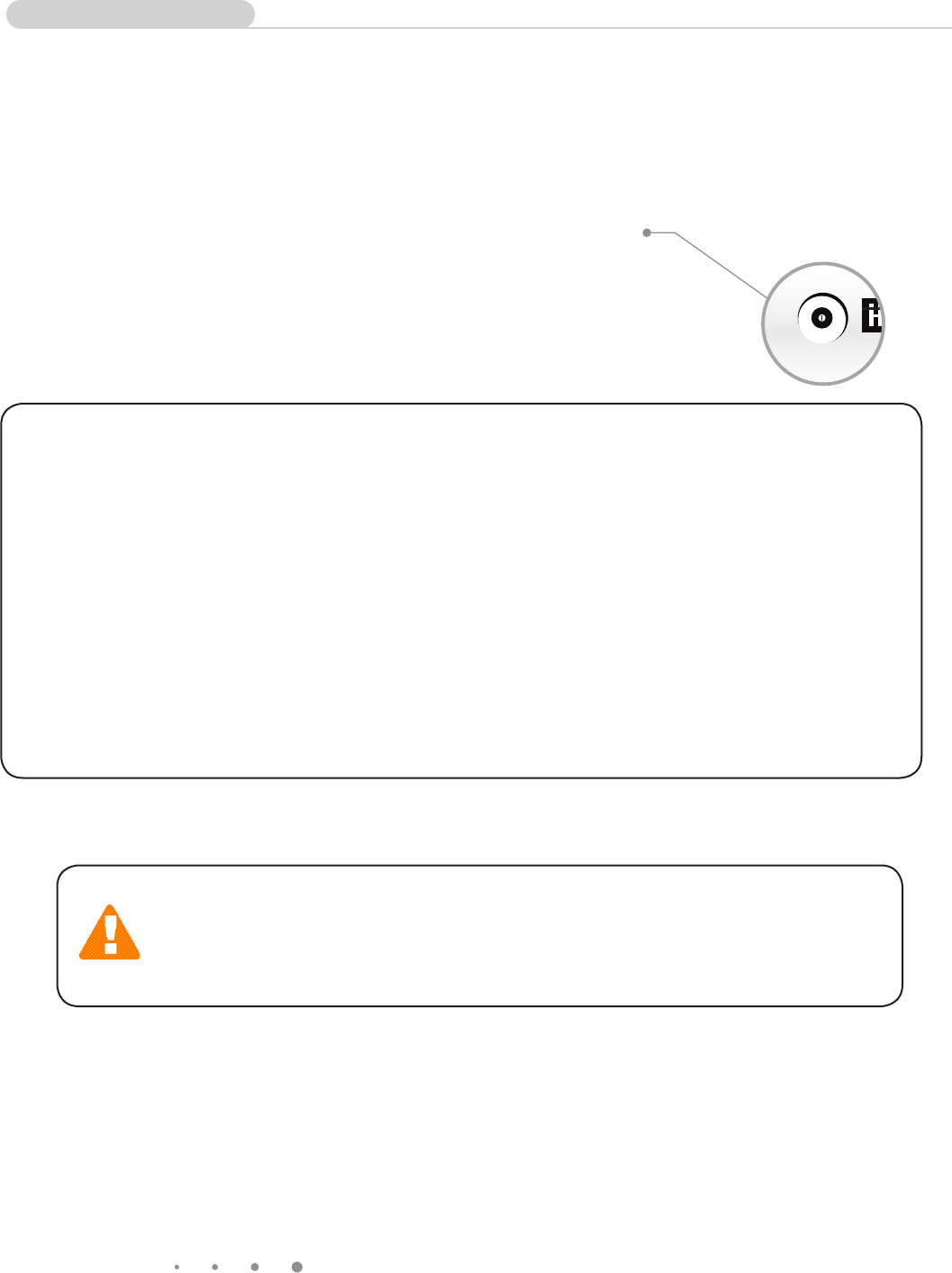
Normal Operation
Afterthe30secondsof“learnmode”transmission,theVehicleSensorperformsaninitialcalibrationsequence.
Calibrationlastsabout15seconds.DONOTmovethesensor,anyvehicles,orlargemetalobjectsnearthe
VehicleSensorduringthis15secondperiod.
Learningandcalibrationisnowcomplete.
TesttheVehicleSensorbydrivingavehiclealongthedrivewayatanormalspeedforthedriveway(5-15mph).
Thegateshouldopenreliablywhenrepeatedseveraltimes.Iftheexitsensordoesnotopenthegateeverytime,
tryincreasing(clockwiserotation)thesettingofthesensitivitypotentiometer.
Whenoperationissatisfactory,installtheoutercoverovertheElectronics/
TransmitterModule,lltheholeandtrenchwithsoilandtamprm.Don’tbe
alarmedifyourgateopenswhileyouarellingthetrenchandhole.
Themetalinyourshovelisactivatingtheexitsensor.
Thisproductandanyaccessoryyoupurchaseshouldonlybeinstalledonagateopener
thatmeetsthecurrentsafetystandard,UL325,4thEdition.Ifyouhaveagateopener
thatisnotlistedwiththecurrentstandardpleasecontacttheGTOsalesdepartmentfor
consultationonagateopenerthatcanmeetyourspecicneeds.
GTO WIRELESS EXIT WAND
TRANSMITTER
MIN MAX
SENSITIVITY
Wireless Exit Sensor
9
GTO Limited One Year Warranty
GTO,Inc.,gateopenersandaccessoriesarecoveredunderwarrantybythemanufactureragainstdefectsinmaterials
andmanufacturerworkmanshipforaperiodofone(1)yearfromdateofpurchase,provided the recommended installation
procedures have been followed.
Inthecaseofproductfailureduetodefectivematerialormanufacturerworkmanshipwithintheone(1)yearwarranty
period,theproductwillberepairedorreplaced(atthemanufacturer’soption)atnochargetothecustomer,ifreturned
freightprepaidtoGTO,Inc.,3121HartseldRoad,Tallahassee,Florida,USA32303.IMPORTANT:Call(800)543-1236for
aReturnGoodsAuthorization(RGA)numberbeforereturningaccessorytofactory.Productsreceivedatthefactory
withoutanRGAnumberwillnotbeaccepted.Replacementorrepairedpartsarecoveredbythiswarrantyfortheremainder
oftheone(1)yearwarrantyperiodorsix(6)months,whicheverisgreater.GTO,Inc.willpaytheshippingcharges(equalto
UnitedParcelServiceGROUNDrate)forreturntotheownerofitemsrepairedunderwarranty.
Themanufacturerwillnotberesponsibleforanychargesordamagesincurredintheremovalofthedefectivepartsforrepair,
orforthereinstallationofthosepartsafterrepair.Thiswarrantyshallbeconsideredvoidifdamagetotheproduct(s)wasdue
toimproperinstallationoruse,connectiontoanimproperpowersource,orifdamagewascausedbylightning,wind,re,
ood,insectsorothernaturalagent.
Aftertheone(1)yearwarrantyperiod,GTO,Inc.willmakeanynecessaryrepairsforanominalfee.CallGTOat(800)
543-1236formoreinformation.Thiswarrantygivesyouspeciclegalrights,andyoumayalsohaveotherrightswhich
mayvaryfromstatetostate.Thiswarrantyisinlieuofallotherwarranties,expressedorimplied.NOTE: Verification of the
warranty period requires copies of receipts or other proof of purchase. Please retain these records.
GTO,Inc.•3121HartseldRoad•Tallahassee,Florida32303
1-800-543-GATE(4283)•TechnicalSupport1-800-543-1236
www.gtopro.com
WhenanEXITSENSORisinuse,theautomaticgateopenercouldbeactivatedbyachildona
bicycle,tricycleorothermetalplayequipment.Thisproductisnotrecommendedforapplications
exposedtochildren.
WARNING
TechnicalSupportHours:MON-FRI8:00AM-7:00PM(ET)
(800) 543-1236
(850) 575-4144
Page
26
Smart Technologies & Investment Ltd. Wireless Wand KIT FCC ID:N9KSMARTECSD2707
NOTE: THE MANUFACTURER IS NOT RESPONSIBLE FOR ANY RADIO OR TV
INTERFERENCE CAUSED BY UNAUTHORIZED MODIFICATIONS TO THIS
EQUIPMENT. SUCH MODIFICATIONS COULD VOID THE USER’S AUTHORITY
TO OPERATE THE EQUIPMENT.