Smart eye Digital Electronics HYIPC-530W IP CAMERA User Manual H Sereis
Shenzhen Smart-eye Digital Electronics Co.,Ltd IP CAMERA H Sereis
UserManual.wiki
>
Smart eye Digital Electronics
>
HYIPC 530W User Manual
Users Manual
Navigation menu
Upload a User Manual
Namespaces
Wiki Guide
HTML
PDF
Info
Views
User Manual
Discussion / Help
Navigation
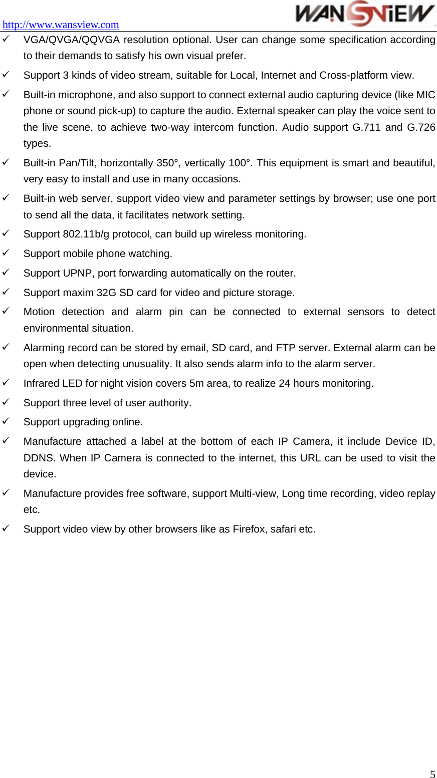
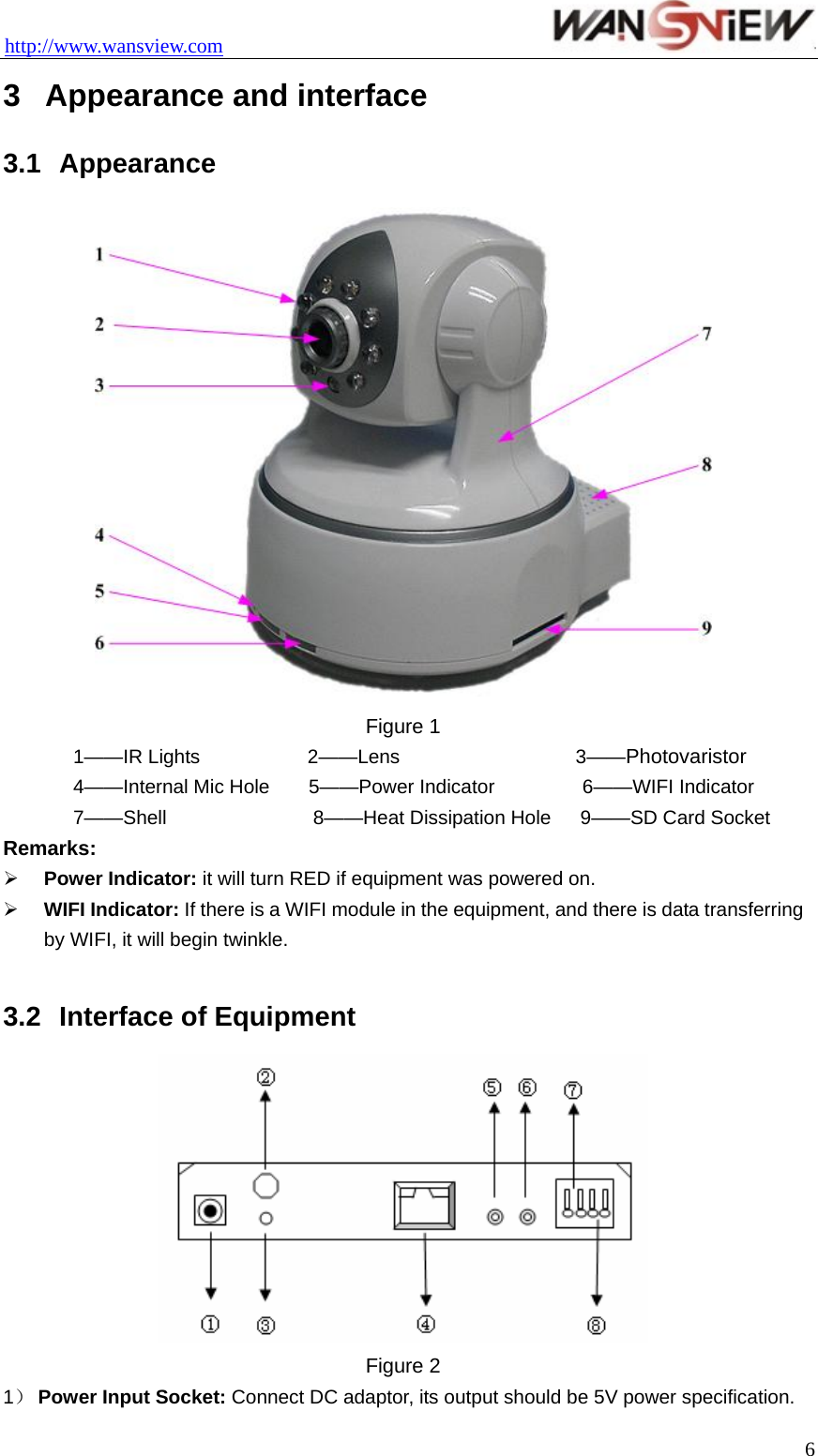
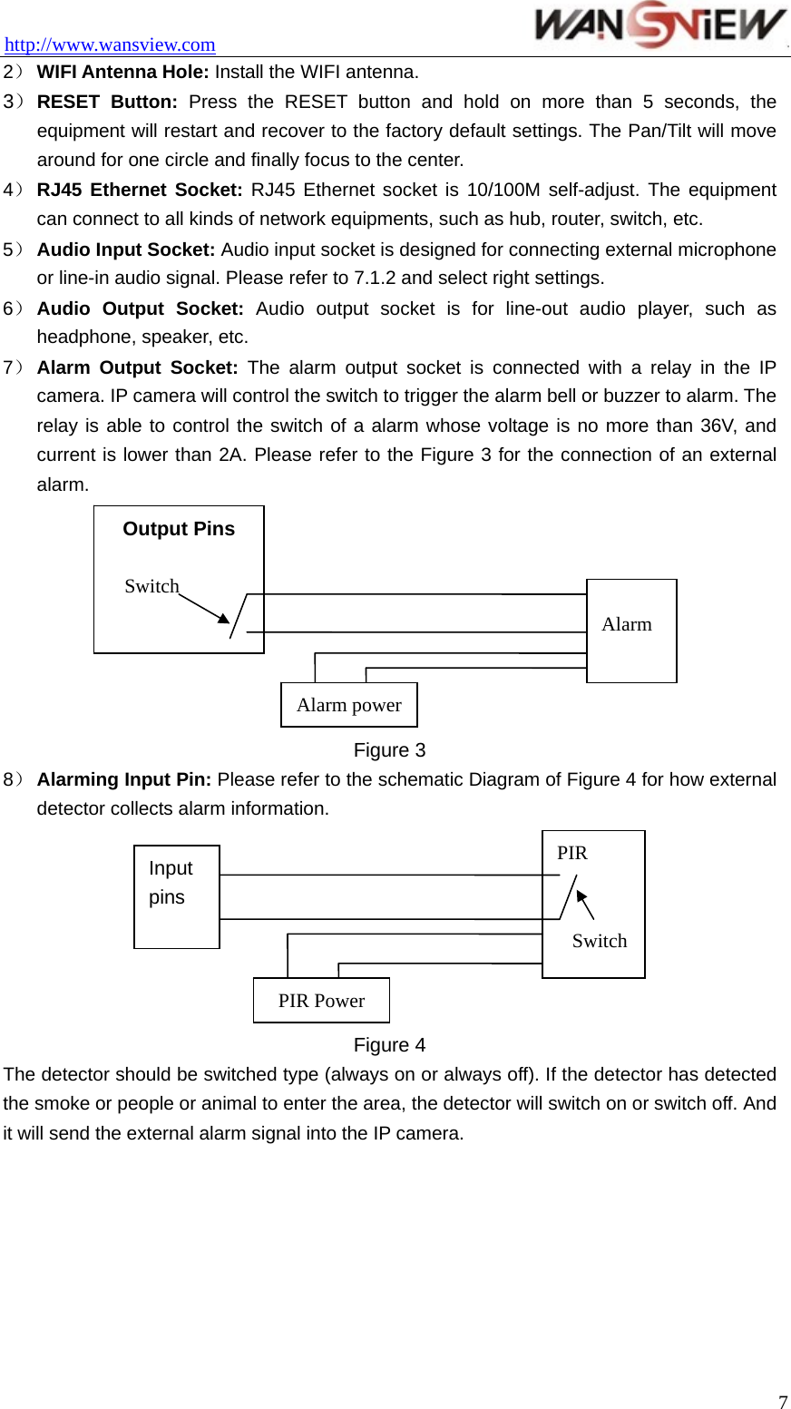
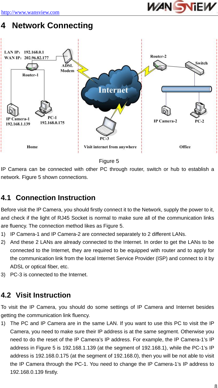
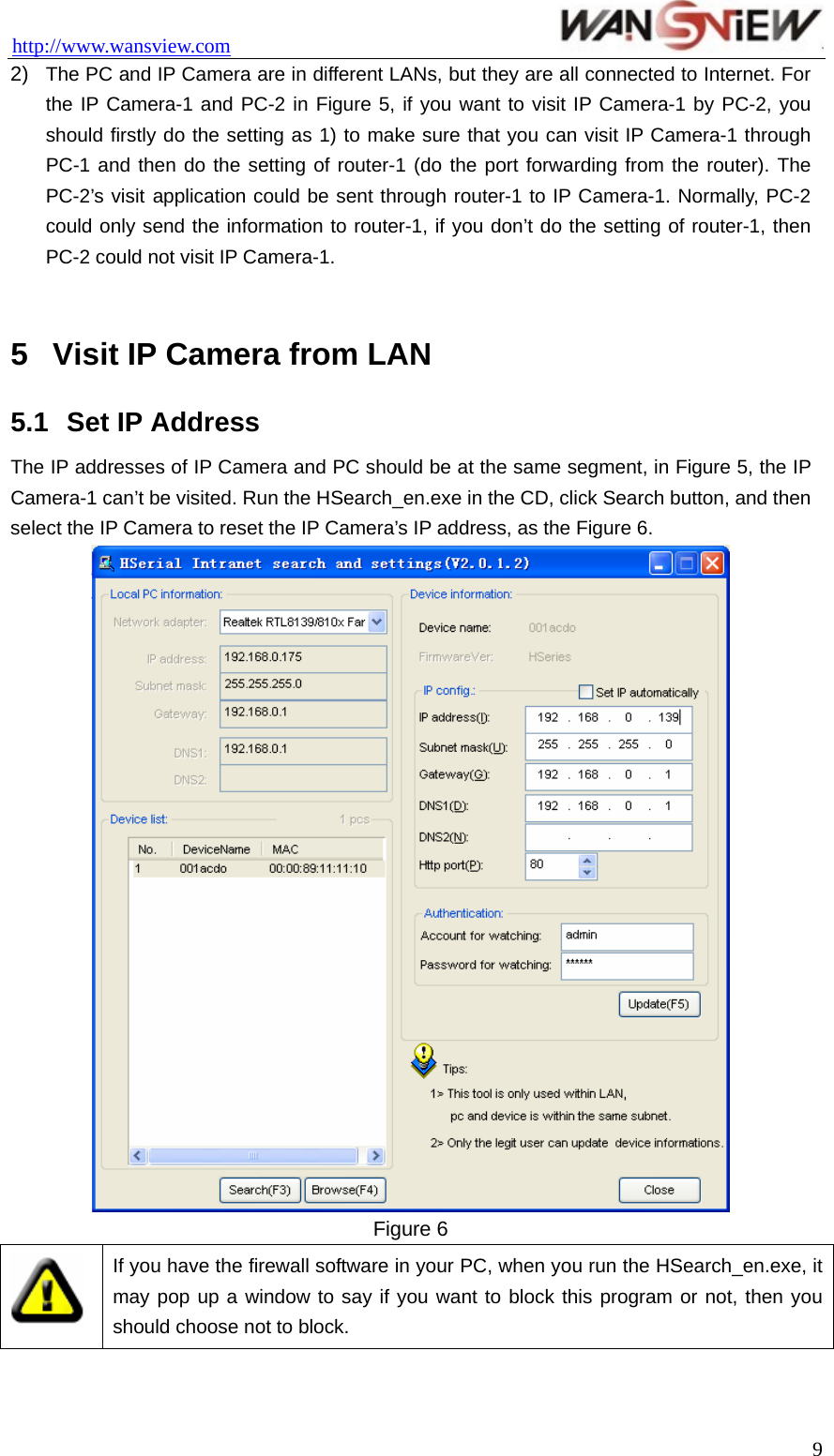
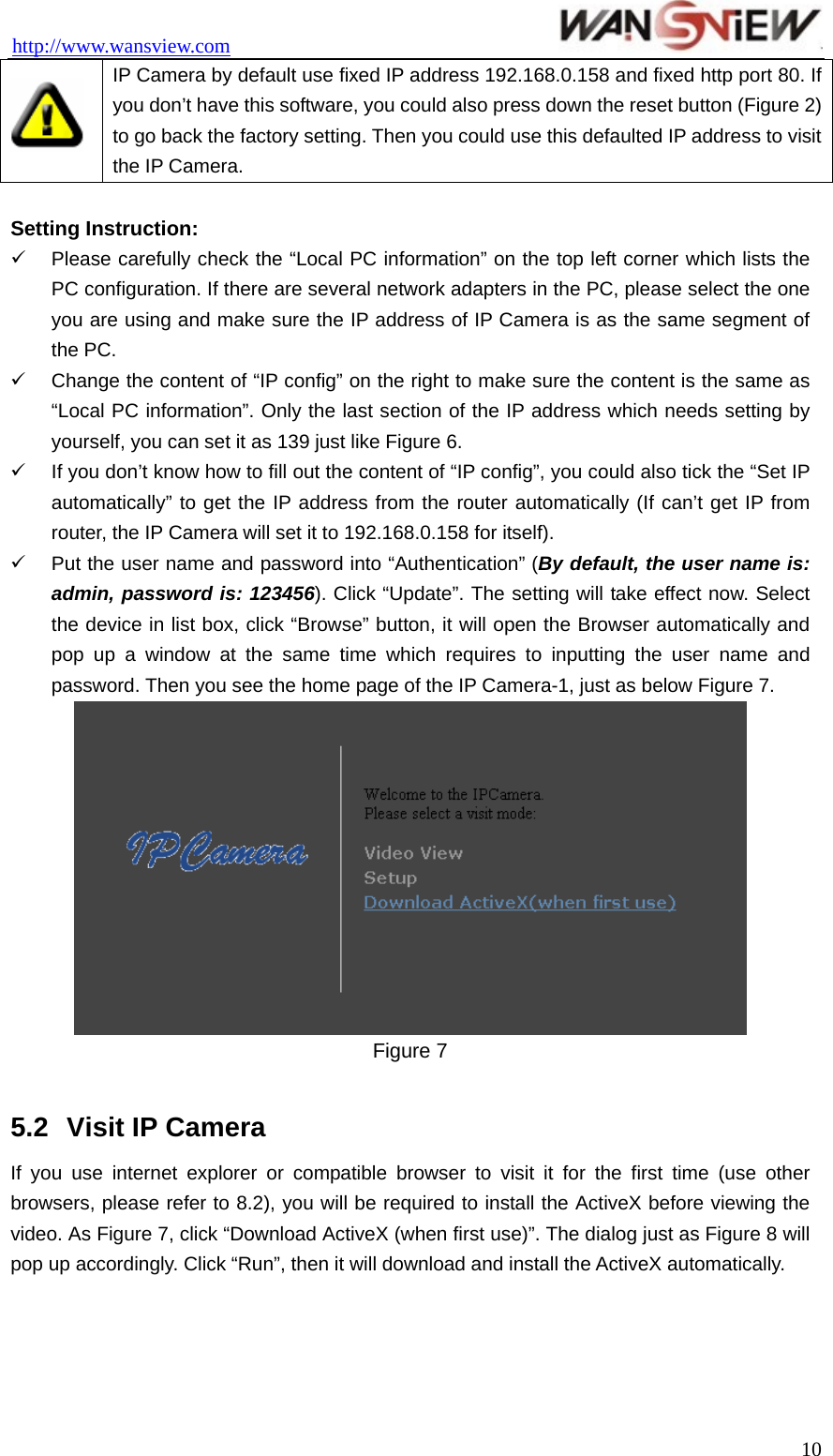
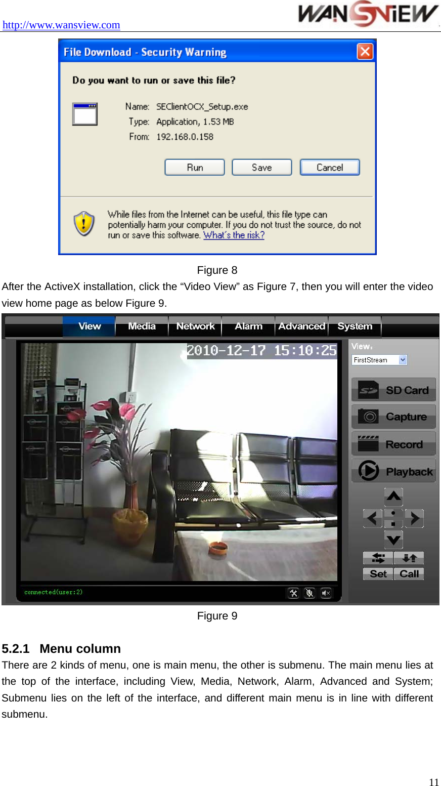
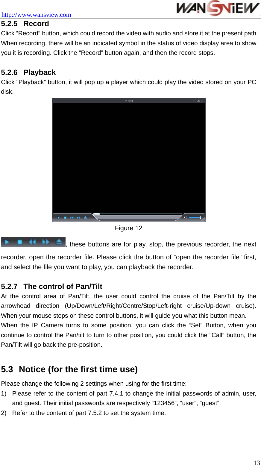
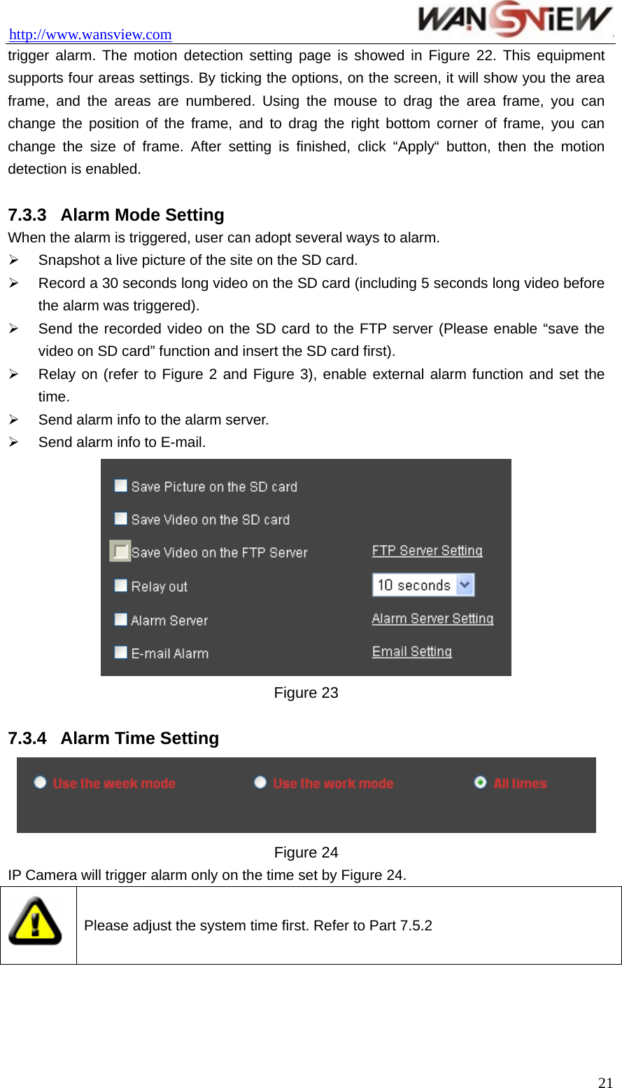
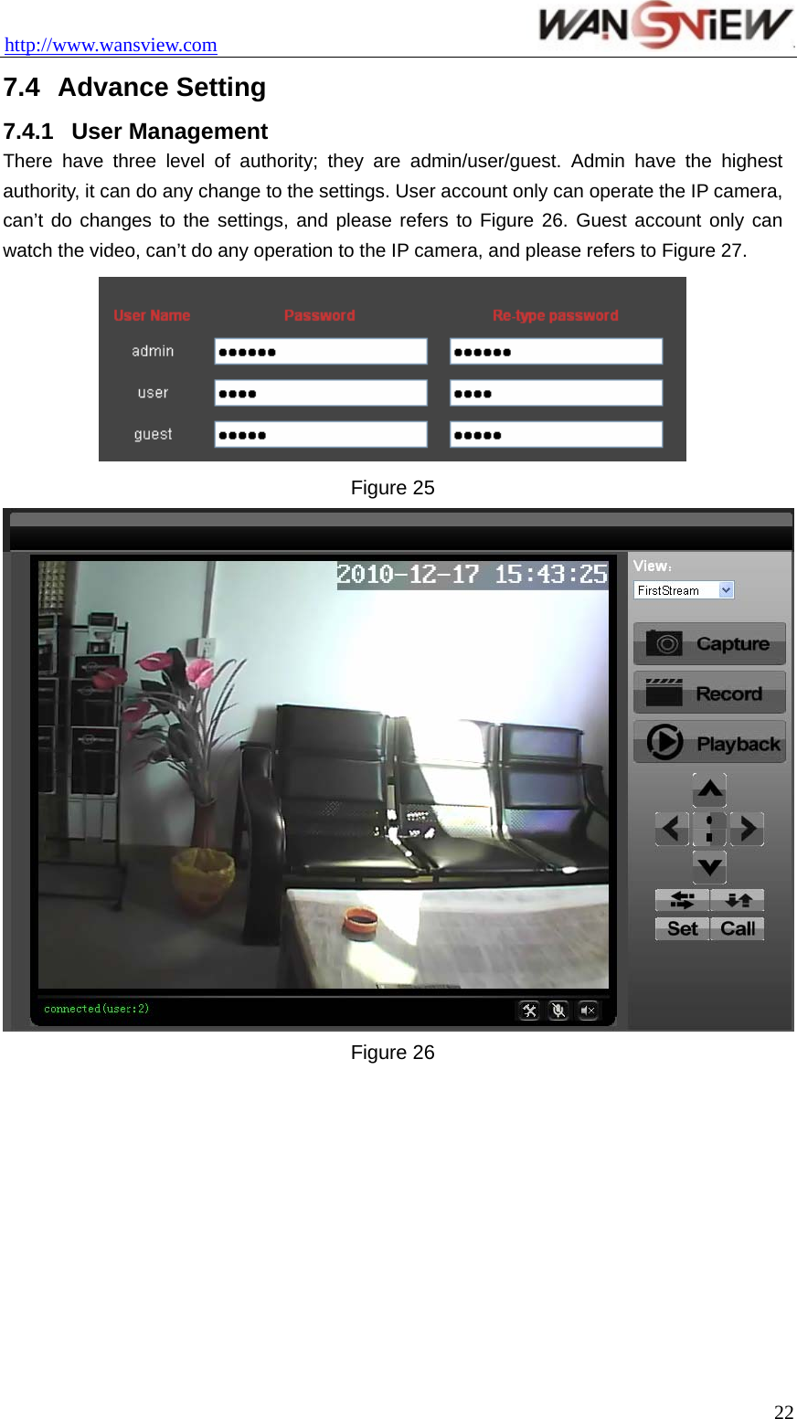
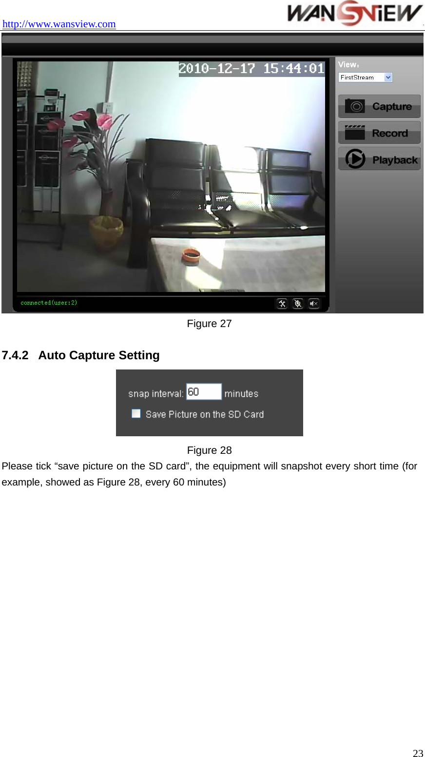
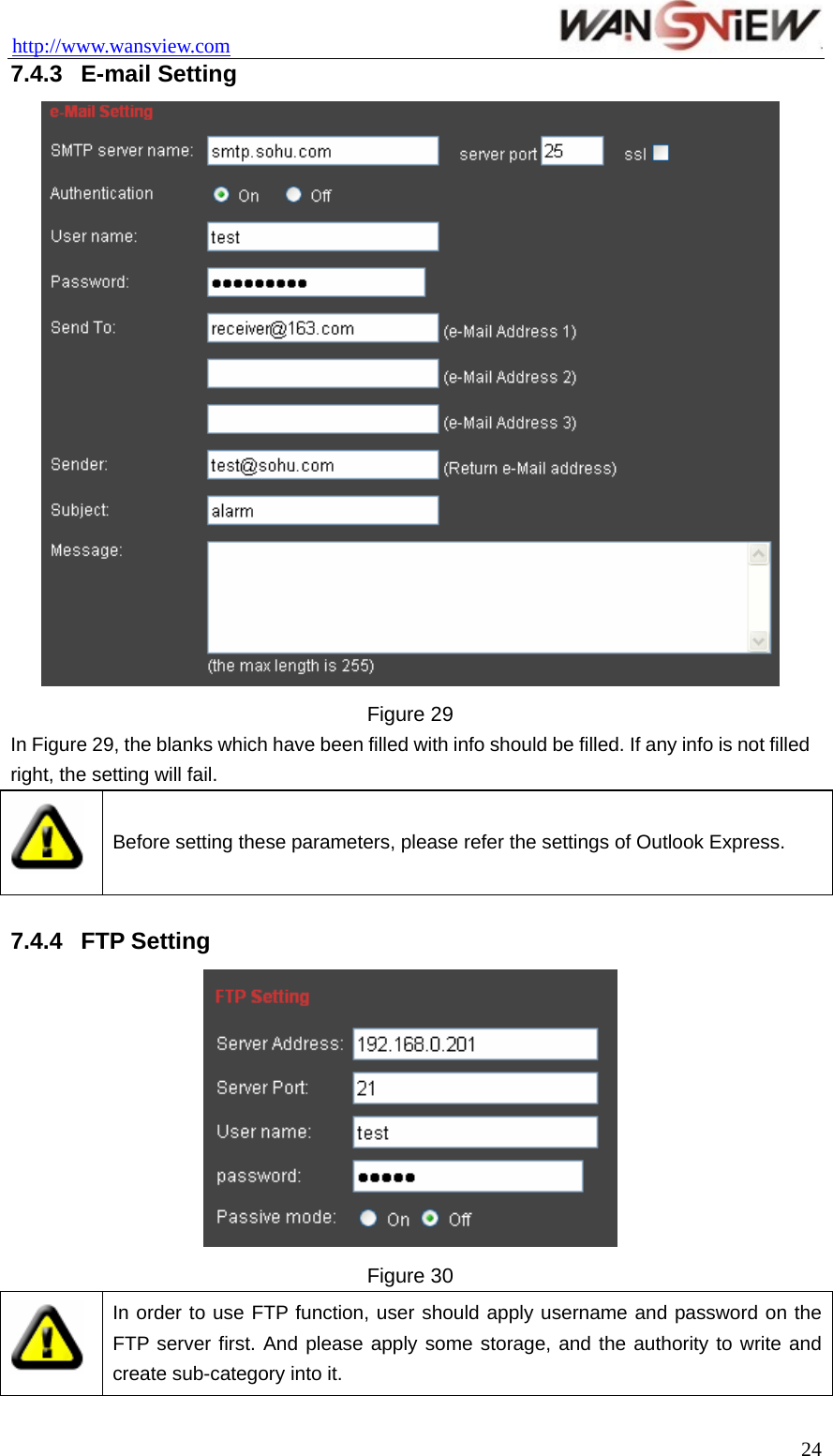
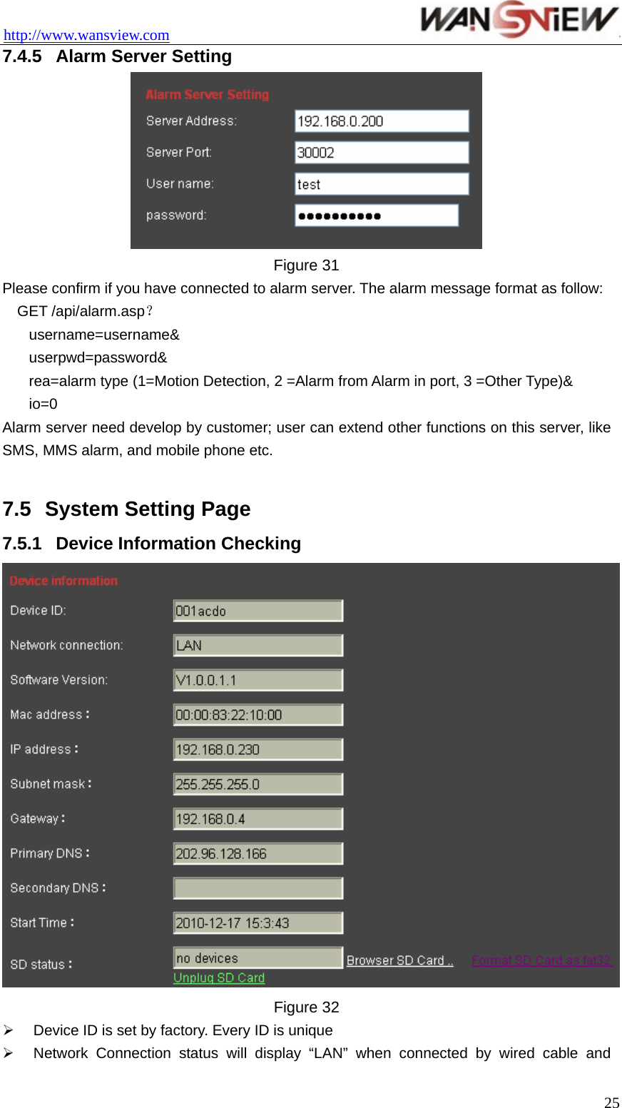
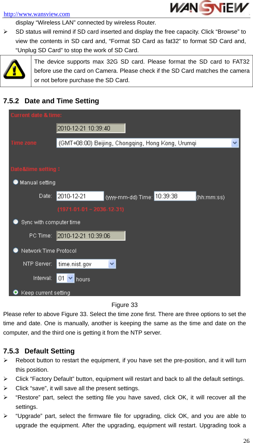
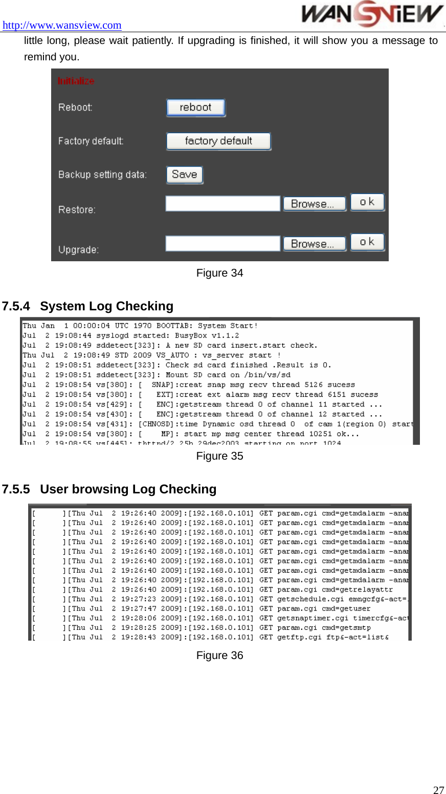
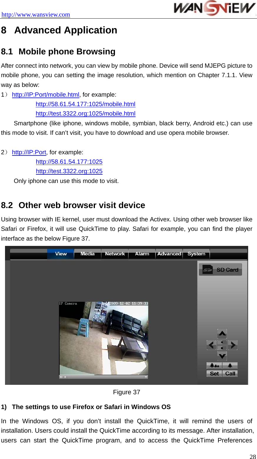
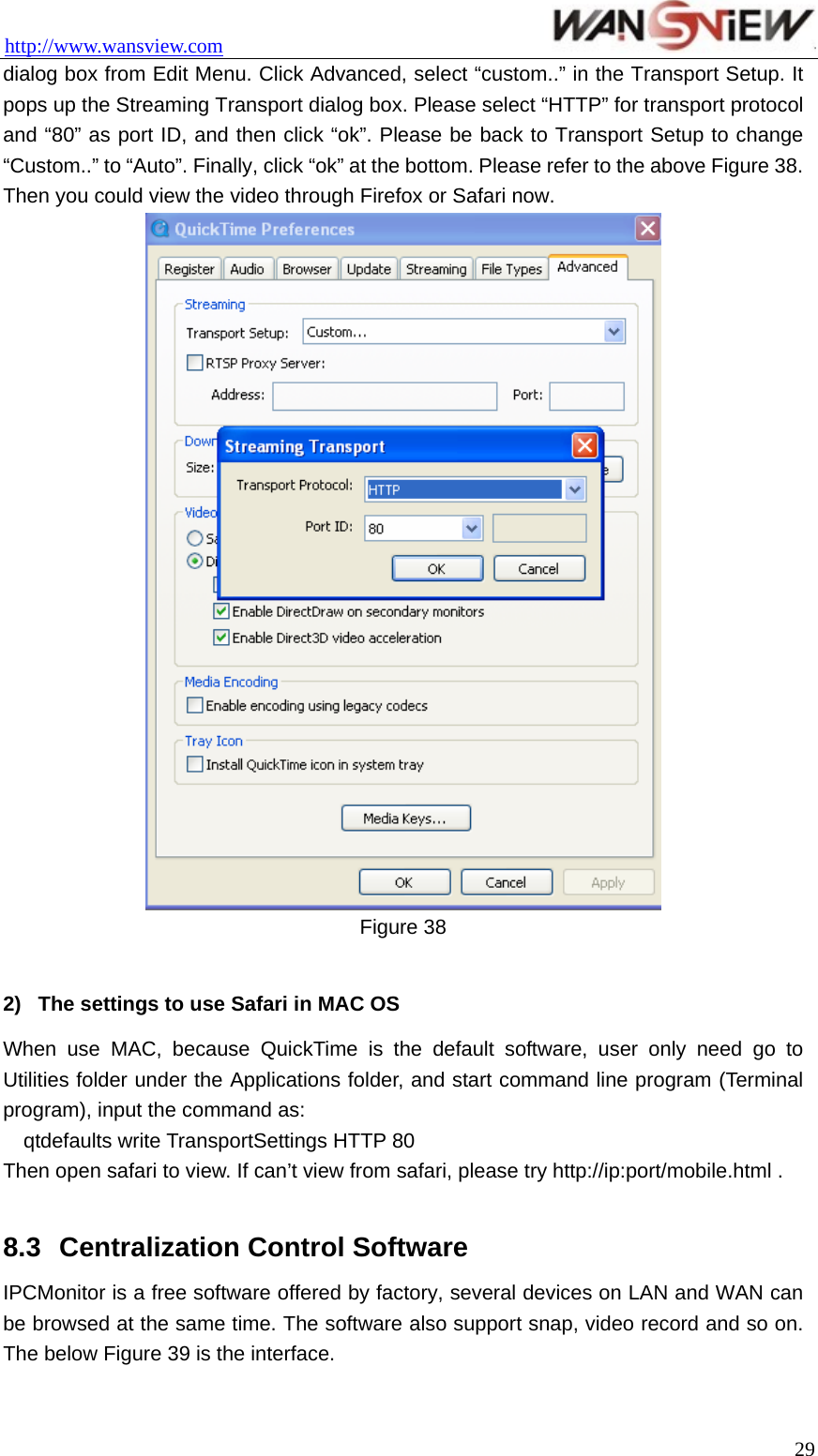
![http://www.wansview.com 5.2.2 Video Displaying Area The video displaying area is correspond to the resolution, the higher the resolution is, larger the displaying area will be. If motion detection was set, when it has detected any movements of the certain area, it will show a pane to call user’s attention. Figure 10 is status column at the bottom of video displaying area. Figure 10 1) Displaying how many users are visiting this video. 2) If user has clicked the “Record” button in the Figure 9, here will show “Rec”, means the video is being recorded. If click the “Record” button again, it will stop recording. 3) File Saving Path Setting: User can click it to browse a file saving path to save the recorded video and snapshots. 4) Talk-back Button: Click it, and the stereo equipment which was connected to the IP Camera will play the achieved audio. Click it again, the speaker will stop playing. 5) Audio Play Button: Click it to play the audio getting from IP Camera, click it again, it will disable this function. 5.2.3 Browse SD Card When SD Card inserted, click the submenu, the pop-up page will display the content in SD Card like the Figure 11. Figure 11 In above figure, text in [ ] is catalog info, click sub catalog to browse the recorded images and videos. The images will be displayed when you click them and the videos will be downloaded and played by the video player in user’s computer automatically when click the video. 5.2.4 Capture Click the “Capture” button, which could take photos for the current video and store the image at the present path. 12](https://usermanual.wiki/Smart-eye-Digital-Electronics/HYIPC-530W/User-Guide-1485543-Page-12.png)