SmartBridges CLIENT AirClient TOTAL 241(Outdoor AP) User Manual Users manual
SmartBridges Pte Ltd AirClient TOTAL 241(Outdoor AP) Users manual
UserManual.wiki
>
SmartBridges
>
CLIENT User Manual
Users manual
Navigation menu
Upload a User Manual
Namespaces
Wiki Guide
HTML
PDF
Info
Views
User Manual
Discussion / Help
Navigation
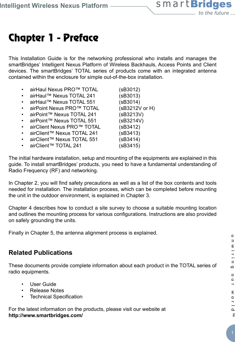
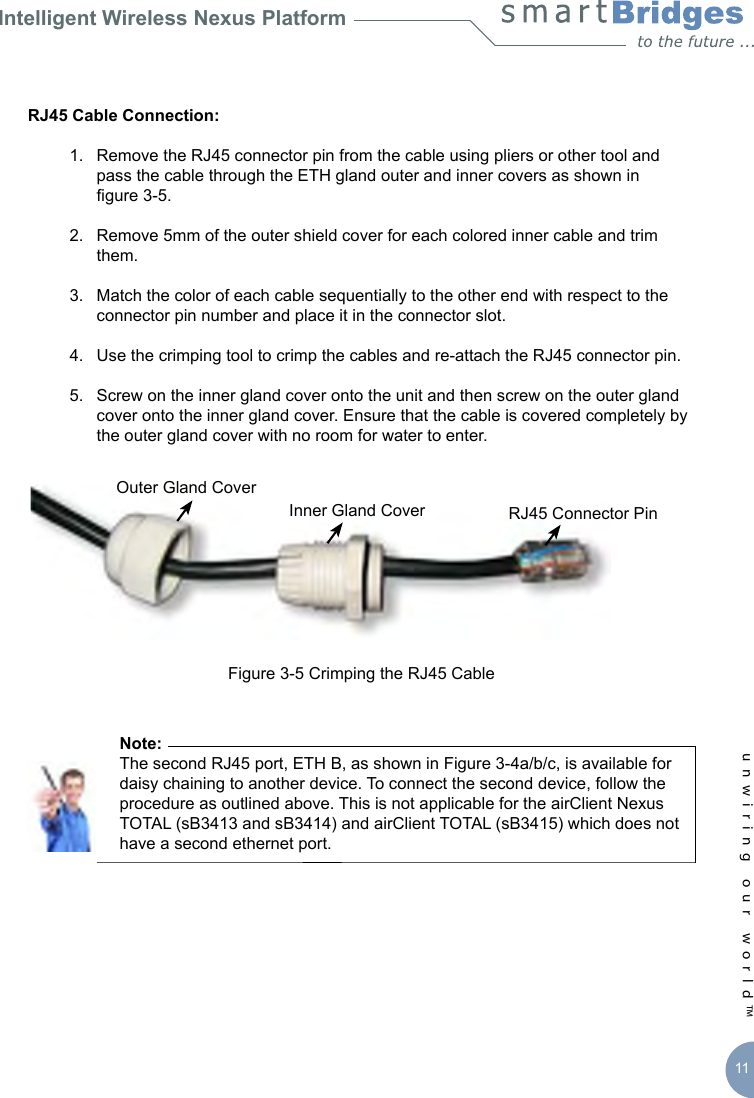

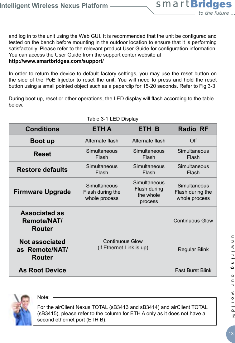
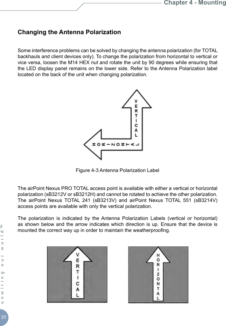
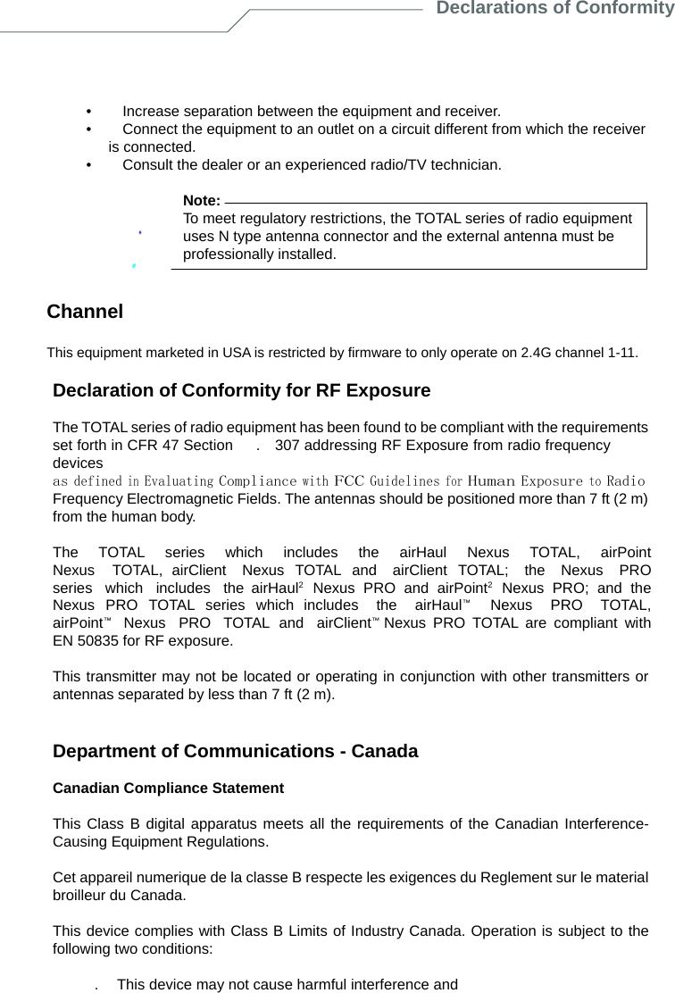
![26unwiring our world™ The following CE mark is afxed to the TOTAL radio equipment.The following smartBridges wireless LAN products use Coded Orthogonal Frequency Division Multiplexing (COFDM) radio technology.airHaul2 Nexus PRO [sB3021]airPoint2 Nexus PRO [sB3221]airHaul Nexus [sB3010] airPoint Nexus [sB3210]airHaul Nexus PRO TOTAL [sB3012]airPoint Nexus PRO TOTAL [sB3212]airClient Nexus PRO TOTAL [sB3412]airHaul Nexus TOTAL 241 [sB3013]airPoint Nexus TOTAL 241 [sB3213]airClient Nexus TOTAL 241 [sB3413]airHaul Nexus TOTAL 551 [sB3014]airPoint Nexus TOTAL 551 [sB3214]airClient Nexus Total 551 [sB3414]These products are designed for wireless point-to-point and point-to-multipoint links conforming to the following standards:Europe - European Union NoticeRadio Products with CE marking comply with R&TTE Directive (1995/5/EC) issued by the Commission of European Community.Compliance with this Directive implies conformity to the following European norms (corresponding international standards are given in brackets).EN 60950 (IEC 60950) - Product and SafetyEN 301.893 – Technical Requirements of Broadband Radio Access Networks; 5 GHz high performance RLANEN 301.489 – General EMC requirement for radio equipmentEN 55022 (CISPR 22) – Electromagnetic InterferenceEN 301.489 (IEC 61000 – 4 – 2, 3, 4, 5, 6, 8, 11) – Electromagnetic ImmunityDeclarations of Conformity](https://usermanual.wiki/SmartBridges/CLIENT/User-Guide-818714-Page-30.png)
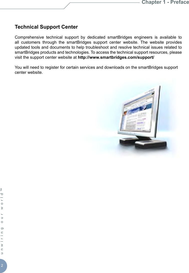
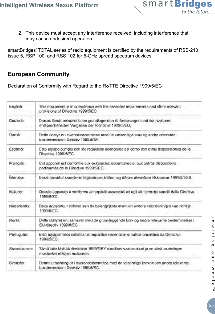
![Intelligent Wireless Nexus Platformunwiring our world™ 27EN 300.328 – General EMC requirements: 2.4 GHz ISM BandCompliance with UK’s regulatory body OFCOM standards – EMI (5.725 to 5.85 GHz) Products containing the radio transmitters are labeled with the CE markingsmartBridges External Multi-band AntennasDish, 29/21 dBi, 24” [sB3802-2921]Panel, 90 degree, 12 dBi, V Pol [sB3802-1290V]Dish, 23/15 dBi, 12” [sB3802-2315]Panel, 90 degree, 12 dBi, H Pol [sB3802-1290H]Panel, 17/15 dBi [sB3802-1715]Caution:During deployment, the RF power should be set so that the total EIRP of the system complies with the power transmission levels set by the local regulatory body.Wireless LAN and your HealthWireless LAN products, like other radio devices, emit radio frequency electromagnetic energy. The level of energy emitted by wireless LAN devices is far less compared to wireless devices like mobile phones. Because wireless LAN products operate within the guidelines and recommendations found in radio frequency safety standards, it is understood that wireless LAN is safe for use by consumers. These standards and recommendations reect the consensus of the scientic community and result from the deliberations of panels and committees of scientists who continually review and interpret the extensive research literature.Regulatory InformationThis device must be installed and used in strict accordance with manufacturer’s instructions as described in the user documentation that comes with the product. For country specic radio and telecommunications approvals, please consult local authorities. In some situations or environments, the use of wireless devices may be restricted by the proprietor of the building or responsible representatives of the organization. These situations may for example include:Using the wireless equipment onboard airplanes, or in any other environment where the risk of interference to other devices or services is perceived or identied as harmful.If you are uncertain of the policy that applies to the use of wireless equipment in a specic organization or environment (e.g. airports), you are required to ask for authorization to use](https://usermanual.wiki/SmartBridges/CLIENT/User-Guide-818714-Page-31.png)
![Intelligent Wireless Nexus Platformunwiring our world™ 29Appendix B – Warranty InformationsmartBridges Limited Warranty, Disclaimer of Warranty, and End User License AgreementCheck latest agreement at URL http://www.smartbridges.com/support/warranty.aspHardwaresmartBridges warrants that commencing from the date of purchase from a smartBridges authorized distributor/reseller to Customer and continuing for a period of 12 months or 16 months from the date of manufacture (whichever is earlier), the Hardware will be free from defects in material and workmanship under normal use. This limited warranty extends only to the original user of the Product. Customer’s sole and exclusive remedy and the entire liability of smartBridges and its suppliers under this limited warranty will be, at smartBridges’ option, shipment of a replacement within the warranty period or a refund of the purchase price if the Hardware is returned to the authorized distributor/reseller supplying it to Customer, freight and insurance prepaid. The Customer is to contact their authorized distributor/reseller for all such matters and proof of purchase might be required. smartBridges replacement parts used in Hardware replacement may be new or equivalent to new. smartBridges’ obligations hereunder are conditioned upon the return of affected Hardware in accordance with smartBridges’ or its service center’s then-current Return Merchandise Authorization (RMA) procedures. This warranty does not cover accidents, misuse, neglect, unauthorized product modication, or acts of nature.SoftwaresmartBridges warrants that commencing from the date of purchase from a smartBridges authorized distributor/reseller to Customer and continuing for a period of 12 months or 16 months from the date of manufacture (whichever is earlier), [a] the media on which the Software is furnished will be free of defects in materials and workmanship under normal use; and [b] the Software substantially conforms to its published specications. This limited warranty extends only to the original user of the Software. Except for the foregoing, the Software is provided AS IS. This limited warranty extends only to the Customer who is the original licensee. Customer’s sole and exclusive remedy and the entire liability of smartBridges and its suppliers and licensors under this limited warranty will be, at smartBridges’ option, repair, replacement, or refund of the Software if reported (or, upon request, returned) to smartBridges or the authorized distributor/reseller supplying the Software to Customer. The Customer is to contact their authorized distributor/reseller for](https://usermanual.wiki/SmartBridges/CLIENT/User-Guide-818714-Page-33.png)