SmartBridges CLIENT AirClient TOTAL 241(Outdoor AP) User Manual Users manual
SmartBridges Pte Ltd AirClient TOTAL 241(Outdoor AP) Users manual
Users manual


unwiring our world™
i
Intelligent Wireless Platform
Contents
Chapter 1 Preface 1
Chapter 2 Before you Begin 3
Safety Precautions and Pre-installation Information
• Safety Precautions
• Required Tools and Cables
• Package Contents
Chapter 3 Installation 7
Overview of the Installation Process
• Typical Radio System Installation
• Connections
• Powering and Resetting the Unit
Chapter 4 Mounting 15
Important Considerations when Choosing
the Mounting Location
• Link Distance
• Signal Path Clearance (Fresnel Zone)
Mounting the Nexus Radio Equipment.
• Tower or Pole Mounting
• Wall Mounting
Chapter 5 Antenna Alignment Overview 21
Instructions on Aligning the Antennas
Appendix A Declarations of Conformity 23
Appendix B Warranty Information 29

Intelligent Wireless Nexus Platform
unwiring our world™
1
Chapter 1 - Preface
This Installation Guide is for the networking professional who installs and manages the
smartBridges’ Intelligent Nexus Platform of Wireless Backhauls, Access Points and Client
devices. The smartBridges’ TOTAL series of products come with an integrated antenna
contained within the enclosure for simple out-of-the-box installation.
• airHaul Nexus PRO™ TOTAL (sB3012)
• airHaul™ Nexus TOTAL 241 (sB3013)
• airHaul™ Nexus TOTAL 551 (sB3014)
• airPoint Nexus PRO™ TOTAL (sB3212V or H)
• airPoint™ Nexus TOTAL 241 (sB3213V)
• airPoint™ Nexus TOTAL 551 (sB3214V)
• airClient Nexus PRO™ TOTAL (sB3412)
• airClient™ Nexus TOTAL 241 (sB3413)
• airClient™ Nexus TOTAL 551 (sB3414)
• airClient™ TOTAL 241 (sB3415)
The initial hardware installation, setup and mounting of the equipments are explained in this
guide. To install smartBridges’ products, you need to have a fundamental understanding of
Radio Frequency (RF) and networking.
In Chapter 2, you will nd safety precautions as well as a list of the box contents and tools
needed for installation. The installation process, which can be completed before mounting
the unit in the outdoor environment, is explained in Chapter 3.
Chapter 4 describes how to conduct a site survey to choose a suitable mounting location
and outlines the mounting process for various congurations. Instructions are also provided
on safely grounding the units.
Finally in Chapter 5, the antenna alignment process is explained.
Related Publications
These documents provide complete information about each product in the TOTAL series of
radio equipments.
• User Guide
• Release Notes
• Technical Specication
For the latest information on the products, please visit our website at
http://www.smartbridges.com/

2
unwiring our world™
Technical Support Center
Comprehensive technical support by dedicated smartBridges engineers is available to
all customers through the smartBridges support center website. The website provides
updated tools and documents to help troubleshoot and resolve technical issues related to
smartBridges products and technologies. To access the technical support resources, please
visit the support center website at http://www.smartbridges.com/support/
You will need to register for certain services and downloads on the smartBridges support
center website.
Chapter 1 - Preface

Intelligent Wireless Nexus Platform
unwiring our world™
3
Chapter 2 - Before you Begin
This chapter provides the safety precautions that you need to follow while installing and
operating the smartBridges units. It contains the following sections:
• Safety Precautions
• Required Tools and Cables
• Box Contents
Safety Precautions
For your safety and to achieve a proper working installation, please read and follow
these safety precautions:
1. Only trained and qualied personnel should install, replace, or service this
product.
2. Select your installation site with safety and performance in mind. Conduct a
proper site survey before deployment.
3. Discuss your plans for installation with your power company. Ask them to visit
your proposed installation site.
4. Plan your installation carefully and completely before you begin. Never perform
the installation alone.
5. Do not locate the product near overhead power lines, circuits or electrical light
sources or where it can come into contact with them. During installation, take
extreme care not to come into contact with such circuits, as they may cause
serious injury or death. For proper installation and grounding of the equipment,
please refer to national and local codes.
Note:
Electric power lines and telephone lines look alike.
6. This product must be grounded. Never operate the equipment in the absence of
a suitably installed ground conductor. Contact the appropriate electrical
inspection authority or an electrician if you are uncertain whether suitable
grounding is available.

4
unwiring our world™
7. When installing the products, remember:
a. Not to use a metal ladder.
b. Not to work on a wet or windy day or when there is lightning.
c. To dress properly: wear shoes with rubber soles and heels, rubber gloves and
long sleeved shirt or jacket.
8. If any part of the equipment should come into contact with a power line, do not
touch it or try to remove it yourself. Call your local power company to have it
removed safely. If an accident occurs involving power lines, please call for
qualied emergency help immediately.
9. Do not work on the equipment or connect or disconnect cables during periods of
lightning activity.
10. Do not operate this product near unshielded blasting caps or in an explosive
environment.
11. In order to comply with Radio Frequency (RF) exposure limits, the antennas for
this product should be positioned at not less than 6.6 ft (2 m) from the human
body.
Required Tools and Cables
You will require the following tools to mount the TOTAL unit:
• 6 mm wrench or socket
• #2 Phillips screwdriver
• Crimping tool
• You may also require tools for user-supplied hardware or fasteners
• CAT5 cable of required length. smartBridges recommends the use of a shielded
CAT5 cable rated for outdoor use.
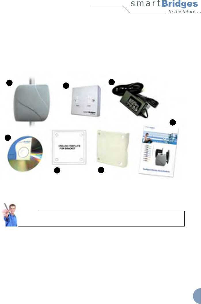
Box Contents
Each TOTAL unit box contains the items listed below. Ensure that all items are included in
the shipment. Notify your vendor if any item is damaged or missing.
1. TOTAL unit
2. Power over Ethernet (PoE) Injector (with mounting screws placed inside the
enclosure)
3. Power module and AC power cord
Chapter 2 - Before you Begin
Intelligent Wireless Nexus Platform
unwiring our world™
5
4. User Guide (Documentation CD)
5. Drilling Template
6. Mounting bracket
7. Quick Installation Guide (this document)
Figure 2-1 Photos of Accessories packed with TOTAL unit.
Note:
The smartBridges equipment shipping box is designed to be eco-friendly.
99.9% of packaging material by weight is bio-degradable.
123
4
7
6
5

6
unwiring our world™
8. An accessories pouch that contains the following items:
a. M8 mm Anchor Hex nuts (4 pieces)
b. M8 mm Anchor washers (4 pieces)
c. M8X60 mm Anchor bolts (4 pieces)
d. M8 mm SS nuts (4 pieces)
e. M8 mm SS plain washers (4 pieces)
f. M8 mm SS spring washers (4 pieces)
g. M8X75 mm SS bolts (4 pieces)
Chapter 2 - Before you Begin
a
b
cd
e
f
g
Intelligent Wireless Nexus Platform
unwiring our world™
7
Chapter 3 – Installation
This chapter provides the hardware installation information for smartBridges’ TOTAL series
of products which come with an integrated antenna. It shows the steps for installation and
connections of all the components before mounting in the outdoor location. This chapter
includes the following sections:
• Typical Radio System Installation
• Connections
• Powering and Resetting the Unit
Typical Radio System Installation
These units are designed to be mounted in an outdoor environment, typically on a tower
or building. The units are shipped with all the required accessories for an out-of-the-box
installation. For mounting information, please refer to Chapter 4.
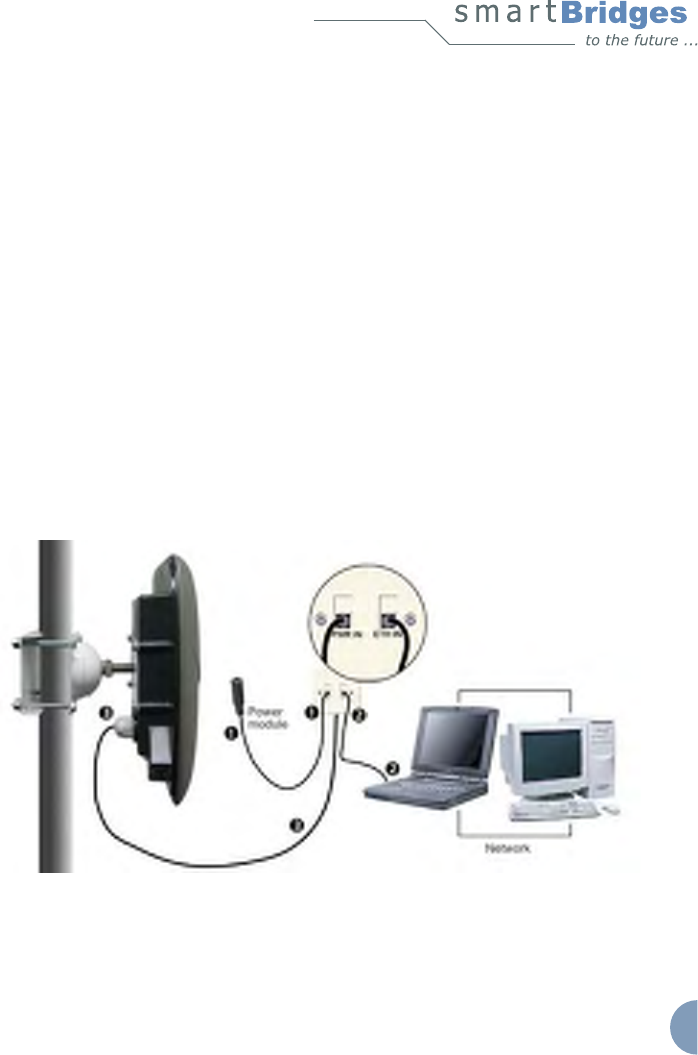
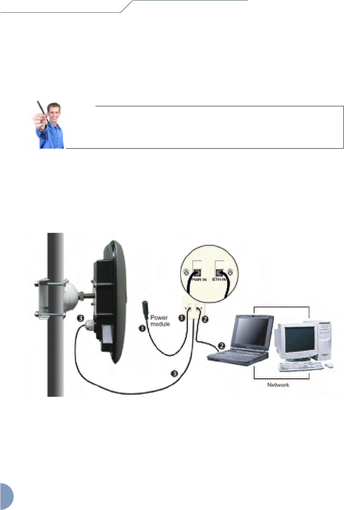
Figure 3-1 below gives an overall view of how the conguration should look like once you
have completed the installation procedures outlined in this chapter and chapter 4.
Figure 3-1 Connections for smartBridges’ TOTAL unit
8
unwiring our world™
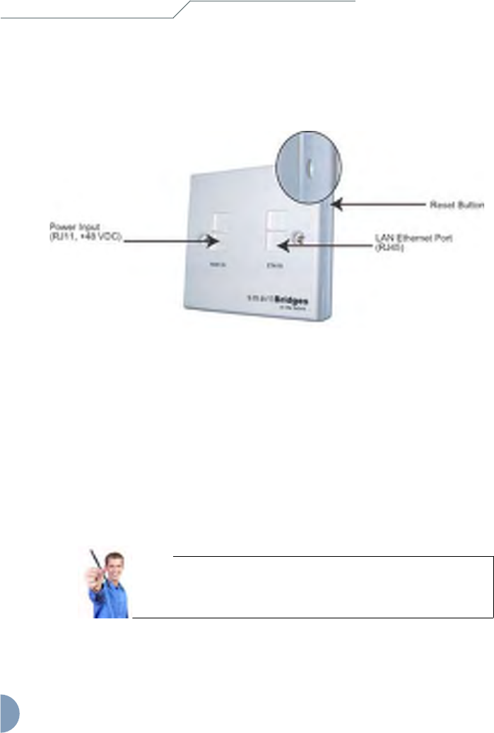
PoE Injector Connections
After grounding the PoE Injector, it can be mounted on a wall or secured otherwise in an
accessible location. Figure 3-3 illustrates the placement of the RJ11 and RJ45 cables.
Figure 3-3 PoE Injector Indicators and Connectors
Connecting the PoE Injector:
1. Connect the PoE Injector to the power module via the PWR IN RJ11 jack
(see Figure 3-3).
2. Connect the PoE Injector to the computer or network via the ETH IN RJ45 jack
(see Figure 3-3).
3. Connect the PoE Injector via the RJ45 jack running from the ETH OUT port on
the back to the Ethernet Port ETH A on the unit (as shown in Figures 3-4a and
3-4b).
Note:
The RJ45 cable connector pin needs to be removed and re-attached
in order to t the ETH port gland on the unit. This is to ensure that the
connections are fully weather-proofed. Please refer to the following
instructions on connecting the RJ45 cable.
Chapter 3 - Installation
Intelligent Wireless Nexus Platform
unwiring our world™
9
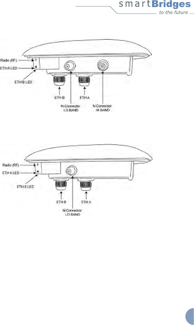
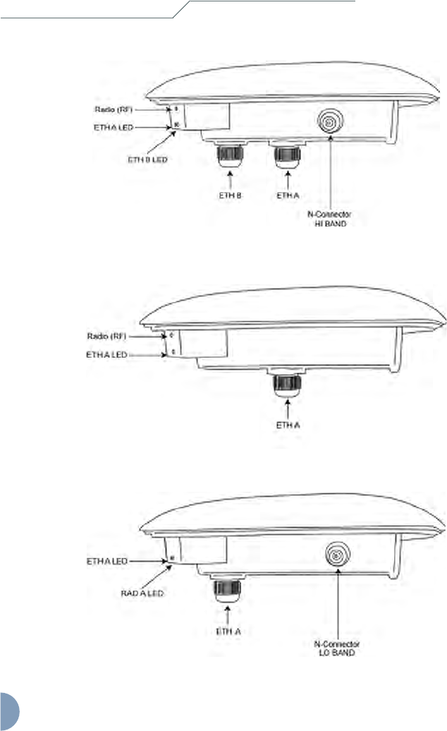
Figure 3-4a Connections on the PRO TOTAL unit
Figure 3-4b Connections on the airHaul and airPoint Nexus TOTAL 241 units (Low Band)
10
unwiring our world™
Figure 3-4c Connections on the airHaul and airPoint Nexus TOTAL 551 units (High Band)
Figure 3-4d Connections on the airClient Nexus TOTAL 241 (Low Band) and
airClient Nexus TOTAL 551 (High Band) units
Figure 3-4e Connections on the airClient TOTAL 241 (Low Band) unit
Chapter 3 - Installation
Intelligent Wireless Nexus Platform
unwiring our world™
11
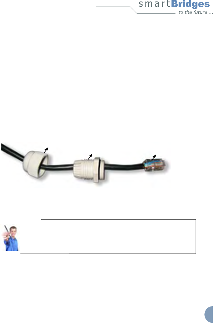
RJ45 Cable Connection:
1. Remove the RJ45 connector pin from the cable using pliers or other tool and
pass the cable through the ETH gland outer and inner covers as shown in
gure 3-5.
2. Remove 5mm of the outer shield cover for each colored inner cable and trim
them.
3. Match the color of each cable sequentially to the other end with respect to the
connector pin number and place it in the connector slot.
4. Use the crimping tool to crimp the cables and re-attach the RJ45 connector pin.
5. Screw on the inner gland cover onto the unit and then screw on the outer gland
cover onto the inner gland cover. Ensure that the cable is covered completely by
the outer gland cover with no room for water to enter.
Figure 3-5 Crimping the RJ45 Cable
Note:
The second RJ45 port, ETH B, as shown in Figure 3-4a/b/c, is available for
daisy chaining to another device. To connect the second device, follow the
procedure as outlined above. This is not applicable for the airClient Nexus
TOTAL (sB3413 and sB3414) and airClient TOTAL (sB3415) which does not
have a second ethernet port.
Outer Gland Cover
Inner Gland Cover RJ45 Connector Pin
12
unwiring our world™
Antenna Connections
The TOTAL series of products provides the exibility of using an external antenna through
the N-Connector.
Note:
This is not applicable for the airClient Nexus TOTAL (sB3413 and sB3414)
which do not have an external antenna connector.
To connect the external antenna:
1. Connect the antenna RF cable to the correct N-Connector (please see
Figure 3-4a/b/c/e).
After completing all the connections, the radio system should look similar to the following
gure.
Figure 3-6 Typical TOTAL radio system
Powering and Resetting the Unit
After performing the installations and connections as shown in Figure 3-6, you may boot up
Chapter 3 - Installation

Intelligent Wireless Nexus Platform
unwiring our world™
13
and log in to the unit using the Web GUI. It is recommended that the unit be congured and
tested on the bench before mounting in the outdoor location to ensure that it is performing
satisfactorily. Please refer to the relevant product User Guide for conguration information.
You can access the User Guide from the support center website at
http://www.smartbridges.com/support/
In order to return the device to default factory settings, you may use the reset button on
the side of the PoE Injector to reset the unit. You will need to press and hold the reset
button using a small pointed object such as a paperclip for 15-20 seconds. Refer to Fig 3-3.
During boot up, reset or other operations, the LED display will ash according to the table
below.
Table 3-1 LED Display
Conditions ETH A ETH B Radio RF
Boot up Alternate ash Alternate ash Off
Reset Simultaneous
Flash
Simultaneous
Flash
Simultaneous
Flash
Restore defaults Simultaneous
Flash
Simultaneous
Flash
Simultaneous
Flash
Firmware Upgrade
Simultaneous
Flash during the
whole process
Simultaneous
Flash during
the whole
process
Simultaneous
Flash during the
whole process
Associated as
Remote/NAT/
Router
Continuous Glow
(if Ethernet Link is up)
Continuous Glow
Not associated
as Remote/NAT/
Router
Regular Blink
As Root Device Fast Burst Blink
Note:
For the airClient Nexus TOTAL (sB3413 and sB3414) and airClient TOTAL
(sB3415), please refer to the column for ETH A only as it does not have a
second ethernet port (ETH B).

14
unwiring our world™
Chapter 3 - Installation

Intelligent Wireless Nexus Platform
unwiring our world™
15
Chapter 4 - Mounting
This section describes how to physically mount the smartBridges’ TOTAL series of products
on the site. The chapter contains the following sections:
• Important Considerations when Choosing the Mounting Location
1. Link Distance
2. Signal Path Clearance (Fresnel Zone)
• Mounting the TOTAL Unit
1. Tower or Pole Mounting
2. Wall Mounting
• Changing Antenna Polarization
Important Considerations when Choosing the Mounting
Location
Each Radio Frequency (RF) application is a unique installation. A site survey is needed
to determine the optimum use of the TOTAL unit to optimize link distance, coverage, and
network performance. The most important considerations are link length and clearance from
obstacles.
The following operating and environmental conditions should be taken into account when
performing a site survey:
• Data rates - Sensitivity and range are inversely proportional to data bit rates. The
data rate increases with a decrease in link distance and/or decrease in receiver
sensitivity.
• Antenna placement - Proper antenna conguration is critical in maximizing radio
range in maximizing radio range. In general, greater heights allow for longer
distances and the avoidance of obstructions. However, do not install the TOTAL
unit at the extreme top of a tower, radio mast or high building to minimize risk of
being directly struck by lightning. It is advisable to install it at least 2 feet below
such heights. Extra height may also increase potential interference from other
unlicensed radio systems.
Note:
Do not install the unit in the proximity of a TV or Radio receiving mast.

16
unwiring our world™
• Physical environment - Clear, open areas provide better radio range than
enclosed, crowded areas. Physical obstructions such as buildings, trees, or hills
can hinder performance of wireless devices. Avoid locating the TOTAL unit
where there is an obstruction between the sending and receiving antennas.
1. Link Distance
If there is no obstacle in the signal path, the maximum link distance depends primarily on the
type of antenna and the free space path loss. Ensure that your proposed mounting site is
within range of the remote antenna. To help estimate the range, the TOTAL unit has a built-in
Link Budget Calculator under Tools in the Web GUI which is accessible upon logging into
the unit. Please refer to the product User Guide for more information on this tool.
2. Signal Path Clearance (Fresnel Zone)
A radio beam travels from one antenna to another in a straight line. Therefore, the path
between the antennas must be free of major obstacles. The effects of obstacles and terrain,
both along and near the path, have a signicant bearing on the propagation of radio signals
and can cause both interference and signal cancellation.
When choosing a site, consider the effects of the following common obstacles:
• Trees and large plants - A tree directly in the signal path can completely block the
signal. You can avoid this by leaving sufcient clearance above the treetops.
You may need to leave extra clearance above smaller tress to allow for future
growth into the signal path.
• Man-made obstacles - A large round building such as a gas storage
reservoir or water tower that is partially in the path may cause some blocking.
These obstacles may also reect RF, which can lead to multi path interference
with other receivers. Objects in or near the path that have rectangular surfaces
can block and diffract signals over and around them.
• Earth surface - The earth’s curvature may also interfere with the signal if the
antenna is mounted too low. Mount the antenna just high enough to allow
adequate clearance from the ground.
Note:
For tower installations, you may need to climb the tower to verify a
clear signal path to the other antenna.
Chapter 4 - Mounting

Intelligent Wireless Nexus Platform
unwiring our world™
17
Table 4-1 (below) is a guide to determine the amount of clearance to leave around the signal
path. Install the bridge or external antenna where obstacles along the propagation path,
including the ground, are no closer than these values.
Table 4-1 Fresnel Zone Clearance Guidelines for Frequencies
Total Path
Length in Miles
(kilometers)
Clearance Radius
around Signal path
in Feet (meters)
2.4GHz
Clearance Radius
around Signal Path
in Feet (meters)
5.x GHz
4 (6) 27.6 (8.4) 17.9 (5.4)
6 (10) 33.8 (10.3) 22.0 (6.7)
8 (13) 39.1 (11.9) 25.4 (7.7)
10 (16) 43.7 (13.3) 28.4 (8.6)
12 (20) 47.9 (14.5) 31.1 (9.4)
For more information on site survey techniques, please visit
http://www.smartbridges.com/education/
Note:
Before proceeding to mount the units in the outdoor location, it is strongly
recommended that they be congured and tested on the bench rst to ensure
that they operate satisfactorily. Please refer to the product User Guide for
conguration information.
18
unwiring our world™
Mounting the Equipment
The TOTAL unit is shipped with mounting hardware that accommodates tower, mast or
rooftop installations. This section describes the mounting process for each installation. The
unit must be professionally installed. The installer must understand wireless techniques,
antenna alignment, adjustment and grounding techniques.
The TOTAL unit is designed for a quick and simple out-of-the-box installation. Remove the
unit from the shipping box and locate the mounting plate with the M14 HEX bolt and nut.
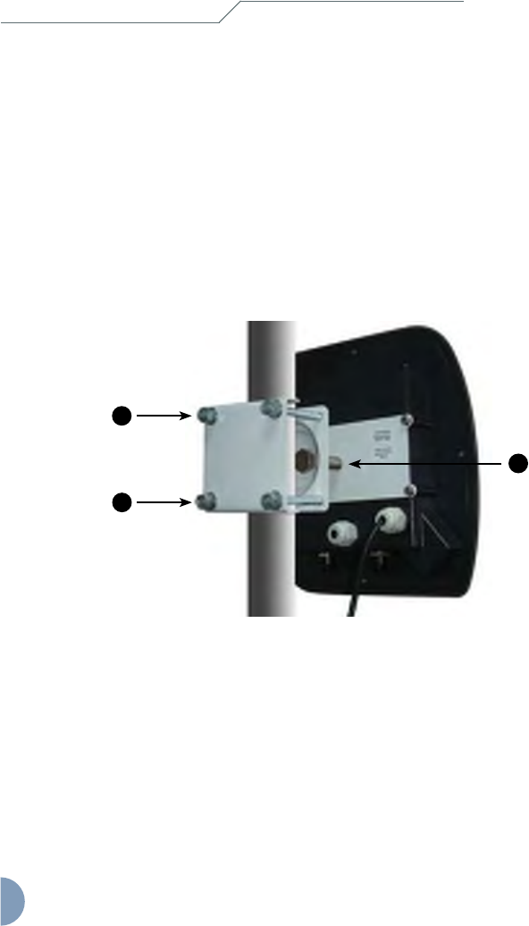
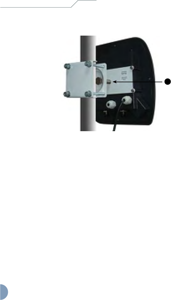
1. Tower or Pole Mounting
Figure 4-1 Tower or Pole Mounting
To mount the unit on a tower or pole, follow the steps below:
1. Find a suitable mounting location on the tower and hoist the entire assembly to
the selected location.
2. Position the assembly as shown in Figure 4-1 and attach the mounting plate to
the tower or pole using the 4 supplied M8x75 mm SS bolts, which t 0.5 to 2.0
inch poles. Use the two sets of washers between the bracket and the nut/bolt
head (see Figure 4-1).
Chapter 4 - Mounting
2
2
3

Intelligent Wireless Nexus Platform
unwiring our world™
19
3. Loosen the M14 HEX nut and adjust the vertical and horizontal alignment of the
unit to point towards the remote base station.
2. Wall Mounting
Follow these steps to wall mount the TOTAL unit using the same wall/pole mounting
plate:
1. Choose a location on the wall where you are going to install the unit.
2. Mark the drill hole locations on the wall using the template provided.
3. Drill the wall to a depth of 2 inches (50 mm) with a 0.3 inch (8mm) diameter.
4. Drive the M8X60 mm Anchor bolt inside each hole and ensure that it is rmly
xed to the wall.
5. Place the mounting plate over the Anchor bolts already inserted onto the wall
and secure them with the 4 M8 mm Anchor HEX nuts provided. Use the washer
between the nut and the bracket (see Figure 4-2).
6. Loosen the M14 HEX nut and adjust the vertical and horizontal alignment of the
antenna to point towards the remote base station.
Figure 4-2 Wall Mounting
5
5
6
20
unwiring our world™
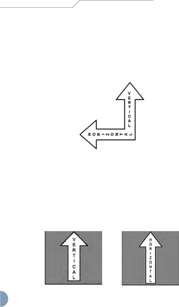
Changing the Antenna Polarization
Some interference problems can be solved by changing the antenna polarization (for TOTAL
backhauls and client devices only). To change the polarization from horizontal to vertical or
vice versa, loosen the M14 HEX nut and rotate the unit by 90 degrees while ensuring that
the LED display panel remains on the lower side. Refer to the Antenna Polarization label
located on the back of the unit when changing polarization.
Figure 4-3 Antenna Polarization Label
The airPoint Nexus PRO TOTAL access point is available with either a vertical or horizontal
polarization (sB3212V or sB3212H) and cannot be rotated to achieve the other polarization.
The airPoint Nexus TOTAL 241 (sB3213V) and airPoint Nexus TOTAL 551 (sB3214V)
access points are available with only the vertical polarization.
The polarization is indicated by the Antenna Polarization Labels (vertical or horizontal)
as shown below and the arrow indicates which direction is up. Ensure that the device is
mounted the correct way up in order to maintain the weatherproong.
Chapter 4 - Mounting

Intelligent Wireless Nexus Platform
unwiring our world™
21
Chapter 5 - Antenna Alignment
This section covers the antenna alignment process to achieve the best radio link performance.
The goal when positioning the unit is to align the antenna for maximum signal strength. In
addition, TOTAL radio units incorporate RSSI Audio Tone to simplify the antenna alignment
process. The RSSI Audio tone is convenient to use and adequate for most installations.
A built-in speaker is provided to monitor the RSSI Audio tone. The TOTAL radios can be
aligned to any angle with in a +/- 30 degree span for a given polarization.
Note:
This chapter is not applicable for the TOTAL access points and airClient
TOTAL (sB3415) as they do not have the RSSI Audio Tone feature.
Establishing Association
On short links where the remote radio is visible, point the unit in the approximate direction
and use the site survey tool to nd the radio at the far end and establish a more precise
association. The integrated antenna is located on the front side of the enclosure.
For longer links where there is no visibility, use the GPS coordinates of the unit at the far
end and calculate its compass direction from the near unit. Point the unit along that precise
direction.
Once the association is established, you can align the antenna using RSSI Audio Tone from
the built-in speaker on the unit. The RSSI Audio produces a tone ranging from 523 Hz (low
pitch) to 2093 Hz (high pitch) that is proportional to the received signal level. The RSSI
Audio Tone provides instantaneous feedback as you move the unit with built-in antenna
within the enclosure.
22
unwiring our world™
Aligning the Antenna Using RSSI Audio Tone
Figure 5-1 Aligning the Unit
To position the antenna using the RSSI Audio tone, follow these steps:
1. Slowly pan the unit to the left and right of the signal path and monitor
the RSSI Audio Tone for peaks in signal strength. Be sure to swing the unit
in an arc of 30 degrees to each side or in a hemispherical cut, while keeping
the desired polarization to ensure that the signal passes through the main and
side lobes of the antenna.
2. Return the unit to the position where the signal is strongest, or in the case of two
similar peaks, halfway between them.
3. Secure the unit by tightening the M14 HEX nut.
After installing and mounting the unit and antennas, please refer to the relevant product
User Guide for more detailed information on conguring the wireless links. For technical
updates, please visit the Support Center website at
http://www.smartbridges.com/support/
For typical deployment scenarios, please visit our website at
http://www.smartbridges.com/products/
Chapter 5 - Antenna Alignment Overview
3

Intelligent Wireless Nexus Platform
Appendix
A
-
Declar
ations
of
Conf
or
mity
This chapter provides declarations of conformity and regulatory information for smartBridges’
Intelligent Nexus Platform of wireless backhauls, access points and client devices.
This appendix contains the following sections:
• FCC Declaration of Conformity Statement
• Declaration of Conformity for RF Exposure
• Department of Communications-Canada Declaration of Conformity Statement
• European Community - Declaration of Conformity Statement
FCC Declaration of Conformity Statement
Models : sB30 2, sB30 3, sB30 4, sB32
2V/H, sB32 3V, sB32 4V, sB34 2,
sB34 3, sB34 4, sB34 5
FCC ID : PWG NEXUS & PWG NEXUS 2
Manufacturer : smartBridges Pte Ltd
745, Toa Payoh Lorong 5
#04-0 , Singapore 3 9455
This device complies with Part- 5 rules. Operation is subject to the
following two conditions:
. This device may not cause harmful interference, and
2. This device must accept any interference received, including interference that
may cause undesired operation.
This transmitter must not be co-located or operating in conjunction with any other antenna or
transmitter.
The antennas used for this transmitter must be installed to provide a separation distance of at
least 20 cm from all persons and must not be co-located or operating in conjunction with any
other antenna or transmitter。
This equipment has been tested to comply with the limits of a Class B
digital device, pursuant to Part 5 of the FCC Rules. These limits are designed to
provide reasonable protection against harmful interference when the equipment is
operated in a residential environment. This equipment generates, uses, and radiates
radio frequency energy, and if not installed and used in accordance with the instructions,
may cause harmful interference. However, there is no guarantee that interference
will not occur. If this equipment does cause interference to radio or television
reception, which can be determined by turning the equipment off and on, the user is
encouraged to correct the interference by one of the following measures:
• Reorient or relocate the receiving antenna. 23

Declarations of Conformity
• Increase separation between the equipment and receiver.
• Connect the equipment to an outlet on a circuit different from which the receiver
is connected.
• Consult the dealer or an experienced radio/TV technician.
Note:
To meet regulatory restrictions, the TOTAL series of radio equipment
uses N type antenna connector and the external antenna must be
professionally installed.
Channel
This equipment marketed in USA is restricted by firmware to only operate on 2.4G channel 1-11.
Declaration of Conformity for RF Exposure
The TOTAL series of radio equipment has been found to be compliant with the requirements
set forth in CFR 47 Section . 307 addressing RF Exposure from radio frequency
devices
as
defined
in
Evaluating
Compliance
with
FCC
Guidelines
for
Human
Exposure
to
Radio
Frequency Electromagnetic Fields. The antennas should be positioned more than 7 ft (2 m)
from the human body.
The TOTAL series which includes the airHaul Nexus TOTAL, airPoint
Nexus TOTAL, airClient Nexus TOTAL and airClient TOTAL; the Nexus PRO
series which includes the airHaul
2
Nexus PRO and airPoint
2
Nexus PRO; and the
Nexus PRO TOTAL series which includes the airHaul
™
Nexus PRO TOTAL,
airPoint
™
Nexus PRO TOTAL and airClient
™
Nexus PRO TOTAL are compliant with
EN 50835 for RF exposure.
This transmitter may not be located or operating in conjunction with other transmitters or
antennas separated by less than 7 ft (2 m).
Department of Communications - Canada
Canadian Compliance Statement
This Class B digital apparatus meets all the requirements of the Canadian Interference-
Causing Equipment Regulations.
Cet appareil numerique de la classe B respecte les exigences du Reglement sur le material
broilleur du Canada.
This device complies with Class B Limits of Industry Canada. Operation is subject to the
following two conditions:
. This device may not cause harmful interference and
Intelligent Wireless Nexus Platform
unwiring our world™
25
2. This device must accept any interference received, including interference that
may cause undesired operation.
smartBridges’ TOTAL series of radio equipment is certied by the requirements of RSS-210
issue 5, RSP 100, and RSS 102 for 5-GHz spread spectrum devices.
European Community
Declaration of Conformity with Regard to the R&TTE Directive 1999/5/EC

26
unwiring our world™
The following CE mark is afxed to the TOTAL radio equipment.
The following smartBridges wireless LAN products use Coded Orthogonal Frequency
Division Multiplexing (COFDM) radio technology.
airHaul2 Nexus PRO
[sB3021]
airPoint2 Nexus PRO
[sB3221]
airHaul Nexus
[sB3010]
airPoint Nexus
[sB3210]
airHaul Nexus PRO TOTAL
[sB3012]
airPoint Nexus PRO TOTAL
[sB3212]
airClient Nexus PRO TOTAL
[sB3412]
airHaul Nexus TOTAL 241
[sB3013]
airPoint Nexus TOTAL 241
[sB3213]
airClient Nexus TOTAL 241
[sB3413]
airHaul Nexus TOTAL 551
[sB3014]
airPoint Nexus TOTAL 551
[sB3214]
airClient Nexus Total 551
[sB3414]
These products are designed for wireless point-to-point and point-to-multipoint links
conforming to the following standards:
Europe - European Union Notice
Radio Products with CE marking comply with R&TTE Directive (1995/5/EC) issued by the
Commission of European Community.
Compliance with this Directive implies conformity to the following European norms
(corresponding international standards are given in brackets).
EN 60950 (IEC 60950) - Product and Safety
EN 301.893 – Technical Requirements of Broadband Radio Access Networks; 5 GHz high
performance RLAN
EN 301.489 – General EMC requirement for radio equipment
EN 55022 (CISPR 22) – Electromagnetic Interference
EN 301.489 (IEC 61000 – 4 – 2, 3, 4, 5, 6, 8, 11) – Electromagnetic Immunity
Declarations of Conformity

Intelligent Wireless Nexus Platform
unwiring our world™
27
EN 300.328 – General EMC requirements: 2.4 GHz ISM Band
Compliance with UK’s regulatory body OFCOM standards – EMI (5.725 to 5.85 GHz)
Products containing the radio transmitters are labeled with the CE marking
smartBridges External Multi-band Antennas
Dish, 29/21 dBi, 24”
[sB3802-2921]
Panel, 90 degree, 12 dBi, V Pol
[sB3802-1290V]
Dish, 23/15 dBi, 12”
[sB3802-2315]
Panel, 90 degree, 12 dBi, H Pol
[sB3802-1290H]
Panel, 17/15 dBi
[sB3802-1715]
Caution:
During deployment, the RF power should be set so that the total EIRP of the system complies
with the power transmission levels set by the local regulatory body.
Wireless LAN and your Health
Wireless LAN products, like other radio devices, emit radio frequency electromagnetic
energy. The level of energy emitted by wireless LAN devices is far less compared to
wireless devices like mobile phones. Because wireless LAN products operate within the
guidelines and recommendations found in radio frequency safety standards, it is understood
that wireless LAN is safe for use by consumers. These standards and recommendations
reect the consensus of the scientic community and result from the deliberations of panels
and committees of scientists who continually review and interpret the extensive research
literature.
Regulatory Information
This device must be installed and used in strict accordance with manufacturer’s instructions
as described in the user documentation that comes with the product. For country specic
radio and telecommunications approvals, please consult local authorities. In some
situations or environments, the use of wireless devices may be restricted by the proprietor
of the building or responsible representatives of the organization. These situations may for
example include:
Using the wireless equipment onboard airplanes, or in any other environment where the risk
of interference to other devices or services is perceived or identied as harmful.
If you are uncertain of the policy that applies to the use of wireless equipment in a specic
organization or environment (e.g. airports), you are required to ask for authorization to use

28
unwiring our world™
this device prior to deploying the equipment.
The manufacturer is not responsible for any radio or television interferences caused by
unauthorized use or modication of the devices included in the manufacturer’s kit, or the
substitution or attachment of connecting cables and equipment other than that specied by
the manufacturer.
The correction of interference caused by such unauthorized modication, substitution or
attachment will be the responsibility of the user.
The manufacturer and its authorized resellers or distributors are not liable for any damage
or violation of government regulations that may arise from failing to comply with these
guidelines.
Declaration of Compliance – RoHS & WEEE
smartBridges Pte Ltd hereby declares that the smartBridges products listed above are
RoHS and WEEE compliant, meeting the European Union RoHS (Restriction of Hazardous
Substances) and WEEE Directives (Waste Electrical and Electronic Equipment).
smartBridges bases its declaration on information provided by its manufacturing partners
and/or component suppliers. It is the responsibility of the third parties to ensure that the
proclaimed compliance is truly adhered. In no event shall smartBridges be held legally
responsible for the declarations of compliance provided by the third parties.
Declarations of Conformity

Intelligent Wireless Nexus Platform
unwiring our world™
29
Appendix B – Warranty Information
smartBridges Limited Warranty, Disclaimer of Warranty, and End User License Agreement
Check latest agreement at URL http://www.smartbridges.com/support/warranty.asp
Hardware
smartBridges warrants that commencing from the date of purchase from a smartBridges
authorized distributor/reseller to Customer and continuing for a period of 12 months or 16
months from the date of manufacture (whichever is earlier), the Hardware will be free from
defects in material and workmanship under normal use. This limited warranty extends only to
the original user of the Product. Customer’s sole and exclusive remedy and the entire liability
of smartBridges and its suppliers under this limited warranty will be, at smartBridges’ option,
shipment of a replacement within the warranty period or a refund of the purchase price if the
Hardware is returned to the authorized distributor/reseller supplying it to Customer, freight
and insurance prepaid. The Customer is to contact their authorized distributor/reseller for
all such matters and proof of purchase might be required. smartBridges replacement parts
used in Hardware replacement may be new or equivalent to new. smartBridges’ obligations
hereunder are conditioned upon the return of affected Hardware in accordance with
smartBridges’ or its service center’s then-current Return Merchandise Authorization (RMA)
procedures. This warranty does not cover accidents, misuse, neglect, unauthorized product
modication, or acts of nature.
Software
smartBridges warrants that commencing from the date of purchase from a smartBridges
authorized distributor/reseller to Customer and continuing for a period of 12 months or 16
months from the date of manufacture (whichever is earlier),
[a] the media on which the Software is furnished will be free of defects in materials and
workmanship under normal use; and
[b] the Software substantially conforms to its published specications.
This limited warranty extends only to the original user of the Software. Except for the
foregoing, the Software is provided AS IS. This limited warranty extends only to the
Customer who is the original licensee. Customer’s sole and exclusive remedy and the
entire liability of smartBridges and its suppliers and licensors under this limited warranty will
be, at smartBridges’ option, repair, replacement, or refund of the Software if reported (or,
upon request, returned) to smartBridges or the authorized distributor/reseller supplying the
Software to Customer. The Customer is to contact their authorized distributor/reseller for

30
unwiring our world™
Warranty Information
all such matters and proof of purchase might be required. In no event does smartBridges
warrant that the Software is error free or that Customer will be able to operate the Software
without problems or interruptions. In addition, due to the continual development of new
techniques for intruding upon and attacking networks, smartBridges does not warrant that
the Software or any equipment, system or network on which the Software is used will be free
of vulnerability to intrusion or attack.
Restrictions
This warranty does not apply if the Software, Product or any other equipment upon which
the Software is authorized to be used (a) has been altered, except by smartBridges or its
authorized representative, (b) has not been installed, operated, repaired, or maintained
in accordance with instructions supplied by smartBridges, or (c) has been subjected to
abnormal physical or electrical stress, misuse, negligence, or accident.
End User License Agreement
IMPORTANT:
PLEASE READ THIS END USER LICENSE AGREEMENT CAREFULLY. DOWNLOADING,
INSTALLING OR USING SMARTBRIDGES’ SOFTWARE CONSTITUTES ACCEPTANCE
OF THIS AGREEMENT. SMARTBRIDGES IS WILLING TO LICENSE THE SOFTWARE
TO YOU ONLY UPON THE CONDITION THAT YOU ACCEPT ALL OF THE TERMS
CONTAINED IN THIS LICENSE AGREEMENT. BY DOWNLOADING OR INSTALLING
THE SOFTWARE, OR USING THE EQUIPMENT THAT CONTAINS THIS SOFTWARE,
YOU ARE BINDING YOURSELF AND THE BUSINESS ENTITY THAT YOU REPRESENT
(COLLECTIVELY, “CUSTOMER”) TO THIS AGREEMENT. IF YOU DO NOT AGREE TO
ALL OF THE TERMS OF THIS AGREEMENT, THEN SMARTBRIDGES IS UNWILLING TO
LICENSE THE SOFTWARE TO YOU AND (A) DO NOT DOWNLOAD, INSTALL OR USE
THE SOFTWARE, AND (B) YOU MAY RETURN THE SOFTWARE FOR A FULL REFUND,
OR, IF THE SOFTWARE IS SUPPLIED AS PART OF ANOTHER PRODUCT, YOU MAY
RETURN THE ENTIRE PRODUCT FOR A FULL REFUND. YOUR RIGHT TO RETURN
AND REFUND EXPIRES 30 DAYS AFTER PURCHASE FROM SMARTBRIDGES OR AN
AUTHORIZED SMARTBRIDGES RESELLER, AND APPLIES ONLY IF YOU ARE THE
ORIGINAL END USER PURCHASER.
The following terms of this End User License Agreement (“Agreement”) govern
Customer’s access and use of the Software, except to the extent (a) there is a separate
signed agreement between Customer and smartBridges governing Customer’s
use of the Software or (b) the Software includes a separate “click-accept” license
agreement as part of the installation and/or download process. To the extent of a
conict between the provisions of the foregoing documents, the order of precedence
shall be (1) the signed agreement, (2) the click-accept agreement, and (3) this End
User License Agreement.

Intelligent Wireless Nexus Platform
unwiring our world™
31
License. Conditioned upon compliance with the terms and conditions of this Agreement,
smartBridges or its subsidiary licensing the Software grants to Customer a nonexclusive and
nontransferable license to use for Customer’s internal business purposes the Software and
the Documentation for which Customer has paid the required license fees. “Documentation”
means written information (whether contained in user or technical manuals, training
materials, specications or otherwise) specically pertaining to the Software and made
available by smartBridges with the Software in any manner (including on CD-Rom, or
on-line). Customer’s license to use the Software shall be limited to, and Customer shall
not use the Software in excess of the applicable Purchase Order which has been paid
to smartBridges the required license fee. Unless otherwise expressly provided in the
Documentation, Customer shall use the Software solely as embedded in, for execution on,
or (where the applicable documentation permits installation on nonsmartBridges equipment)
for communication with smartBridges equipment owned or leased by Customer and used
for Customer’s internal business purposes.
General Limitations. This is a license, not a transfer of title, to the Software and
Documentation, and smartBridges retains ownership of all copies of the Software and
Documentation. Customer acknowledges that the Software and Documentation contain
trade secrets of smartBridges, its suppliers or licensors, including but not limited to the
specic internal design and structure of individual programs and associated interface
information. Accordingly, except as otherwise expressly provided under this Agreement,
Customer shall have no right and Customer specically agrees not to:
i. transfer, assign or sublicense its license rights to any other person or entity,
or use the Software on unauthorized or secondhand smartBridges equipment,
and Customer acknowledges that any attempted transfer, assignment, sublicense or
use shall be void;
ii. make error corrections to or otherwise modify or adapt the Software or create
derivative works based upon the Software, or permit third parties to do the same;
iii. reverse engineer or decompile, decrypt, disassemble or otherwise reduce the
Software to human readable form, except to the extent otherwise expressly permitted
under applicable law notwithstanding this restriction;
iv. use or permit the Software to be used to perform services for third parties, whether
on a service bureau or time sharing basis or otherwise, without the express written
authorization of smartBridges; or
v. disclose, provide, or otherwise make available trade secrets contained within the
Software and Documentation in any form to any third party without the prior written
consent of smartBridges. Customer shall implement reasonable security measures to
protect such trade secrets.

32
unwiring our world™
Warranty Information
To the extent required by law, and at Customer’s written request, smartBridges shall
provide Customer with the interface information needed to achieve interoperability between
the Software and another independently created program, on payment of smartBridges’
applicable fee, if any. Customer shall observe strict obligations of condentiality with respect
to such information and shall use such information in compliance with any applicable terms
and conditions upon which smartBridges makes such information available.
Software, Upgrades and Additional Copies. For purposes of this Agreement, “Software”
shall include (and the terms and conditions of this Agreement shall apply to) computer
programs, including rmware, as provided to Customer by smartBridges or an authorized
smartBridges reseller, and any upgrades, updates, bug xes or modied versions thereto
(collectively, “Upgrades”) or backup copies of the Software licensed or provided to
Customer by smartBridges or an authorized smartBridges reseller. NOTWITHSTANDING
ANY OTHER PROVISION OF THIS AGREEMENT: (1) CUSTOMER HAS NO LICENSE
OR RIGHT TO USE ANY ADDITIONAL COPIES OR UPGRADES UNLESS CUSTOMER,
AT THE TIME OF ACQUIRING SUCH COPY OR UPGRADE, ALREADY HOLDS A VALID
LICENSE TO THE ORIGINAL SOFTWARE AND HAS PAID THE APPLICABLE FEE FOR
THE UPGRADE OR ADDITIONAL COPIES; (2) USE OF UPGRADES IS LIMITED TO
SMARTBRIDGES EQUIPMENT FOR WHICH CUSTOMER IS THE ORIGINAL END USER
PURCHASER OR LESSEE OR WHO OTHERWISE HOLDS A VALID LICENSE TO USE
THE SOFTWARE WHICH IS BEING UPGRADED; AND (3) THE MAKING AND USE OF
ADDITIONAL COPIES IS LIMITED TO NECESSARY BACKUP PURPOSES ONLY.
Proprietary Notices. Customer agrees to maintain and reproduce all copyright and other
proprietary notices on all copies, in any form, of the Software in the same form and manner
that such copyright and other proprietary notices are included on the Software. Except as
expressly authorized in this Agreement, customer shall not make any copies or duplicates
of any Software without the prior written permission of smartBridges.
Term and Termination. This Agreement and the license granted herein shall remain
effective until terminated. Customer may terminate this Agreement and the license at any
time by destroying all copies of Software and any Documentation. Customer’s rights under
this Agreement will terminate immediately without notice from smartBridges if Customer fails
to comply with any provision of this Agreement. Upon termination, Customer shall destroy
all copies of Software and Documentation in its possession or control. All condentiality
obligations of Customer and all limitations of liability and disclaimers and restrictions of
warranty shall survive termination of this Agreement. In addition, the provisions of the
sections titled “U.S. Government End User Purchasers” and “General Terms Applicable
to the Limited Warranty Statement and End User License” shall survive termination of this
Agreement.

Intelligent Wireless Nexus Platform
unwiring our world™
33
General Terms Applicable to the Limited Warranty Statement and
End User License
Disclaimer of Warranty. EXCEPT AS SPECIFIED IN THIS WARRANTY, ALL
EXPRESS OR IMPLIED CONDITIONS, REPRESENTATIONS, AND WARRANTIES
INCLUDING, WITHOUT LIMITATION, ANY IMPLIED WARRANTY OR CONDITION OF
MERCHANTABILITY, FITNESS FOR A PARTICULAR PURPOSE, NON-INFRINGEMENT,
SATISFACTORY QUALITY, NON-INTERFERENCE, ACCURACY OF INFORMATIONAL
CONTENT, OR ARISING FROM A COURSE OF DEALING, LAW, USAGE, OR TRADE
PRACTICE, ARE HEREBY EXCLUDED TO THE EXTENT ALLOWED BY APPLICABLE
LAW AND ARE EXPRESSLY DISCLAIMED BY SMARTBRIDGES, ITS SUPPLIERS AND
LICENSORS. TO THE EXTENT AN IMPLIED WARRANTY CANNOT BE EXCLUDED,
SUCH WARRANTY IS LIMITED IN DURATION TO THE EXPRESS WARRANTY PERIOD.
BECAUSE SOME STATES OR JURISDICTIONS DO NOT ALLOW LIMITATIONS ON HOW
LONG AN IMPLIED WARRANTY LASTS, THE ABOVE LIMITATION MAY NOT APPLY. THIS
WARRANTY GIVES CUSTOMER SPECIFIC LEGAL RIGHTS, AND CUSTOMER MAY
ALSO HAVE OTHER RIGHTS WHICH VARY FROM JURISDICTION TO JURISDICTION.
This disclaimer and exclusion shall apply even if the express warranty set forth above fails
of its essential purpose.
Disclaimer of Liabilities. REGARDLESS WHETHER ANY REMEDY SET FORTH
HEREIN FAILS OF ITS ESSENTIAL PURPOSE OR OTHERWISE, IN NO EVENT WILL
SMARTBRIDGES OR ITS SUPPLIERS BE LIABLE FOR ANY LOST REVENUE, PROFIT,
OR LOST OR DAMAGED DATA, BUSINESS INTERRUPTION, LOSS OF CAPITAL, OR
FOR SPECIAL, INDIRECT, CONSEQUENTIAL, INCIDENTAL, OR PUNITIVE DAMAGES
HOWEVER CAUSED AND REGARDLESS OF THE THEORY OF LIABILITY OR
WHETHER ARISING OUT OF THE USE OF OR INABILITY TO USE SOFTWARE OR
OTHERWISE AND EVEN IF SMARTBRIDGES OR ITS SUPPLIERS OR LICENSORS
HAVE BEEN ADVISED OF THE POSSIBILITY OF SUCH DAMAGES. In no event shall
smartBridges’ or its suppliers’ or licensors’ liability to Customer, whether in contract, tort
(including negligence), breach of warranty, or otherwise, exceed the rice paid by Customer
for the Product that gave rise to the claim. BECAUSE SOME STATES OR JURISDICTIONS
DO NOT ALLOW LIMITATION OR EXCLUSION OF CONSEQUENTIAL OR INCIDENTAL
DAMAGES, THE ABOVE LIMITATION MAY NOT APPLY TO YOU.
The Warranty and the End User License shall be governed by and construed in accordance
with the laws of the Singapore, without reference to or application of choice of law rules
or principles. The United Nations Convention on the International Sale of Goods shall not
apply. If any portion hereof is found to be void or unenforceable, the remaining provisions
of the Agreement shall remain in full force and effect. Except as expressly provided herein,
this Agreement constitutes the entire agreement between the parties and supersedes any
conicting or additional terms contained in any purchase order or elsewhere, all of which
terms are excluded. This Agreement has been written in the English language, and the
parties agree that the English version will govern.

34
unwiring our world™
Warranty Information
Copyright & Trademarks
All trademarks and brand names mentioned in this document are the property of their
respective owners.
For detailed product information and demo, visit www.smartbridges.com/products/
Copyright © 1999-2007 smartBridges. All Rights Reserved.
The content herein is subject to change without further notice. smartBridges, Nexus, Nexus
PRO, Nexus PRO TOTAL, airHaul, airPoint, airClient and/or all other products and/or
services referenced herein are either registered trademarks, trademarks or service marks
of smartBridges Pte Ltd. All other names are/or may be the trademarks of their respective
owners.