SmartLabs 2475DA1 In-Line Hardwired Light Dimming Module User Manual 2475DA1 Owners Manual
SmartLabs, Inc. In-Line Hardwired Light Dimming Module 2475DA1 Owners Manual
Users Manual
April 20, 2012
In-Line Hardwired Light Dimming Module
Model: 2475DA1
FCC ID: SBP2475DA1
IC: 5202A-2475DA1
The owner’s manual below may be accessed freely via the Internet
with any web browser and supports the PDF format.
www.smarthome.com/2475DA1.html
Complies with Section 5 of FCC document 784748 D01 Labeling Part 15 18 Guidelines v07 where
cautionary statements in the user manual may be provided over the Internet.
On-Line Owner’s Manual Containing
Cautionary FCC & IC Statements
Page 1 of 14 2475DA1 - Rev: 4/20/2012 4:35 PM
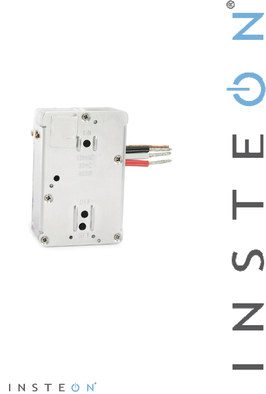
In-LineLinc™
Dimmer
INSTEON® In-LineLinc Dimmer, Dual-Band
Owner’s Manual (#2475DA1)

Page 2 of 14 2475DA1 - Rev: 4/20/2012 4:35 PM
In-LineLinc Dimmer Dual-Band .................................................................................................................3
Features and Benefits.................................................................................................................................3
What’s in the Box?.....................................................................................................................................3
Installation ...................................................................................................................................................4
Identifying the Electrical Wires in your Home............................................................................................4
Tools Needed ............................................................................................................................................4
Installing In-LineLinc Dimmer Dual-Band..................................................................................................5
Using In-LineLinc Dimmer Dual-Band ......................................................................................................6
LEDs..........................................................................................................................................................6
Using the ON and OFF Buttons ................................................................................................................6
Button Functions........................................................................................................................................6
Local On-Level ..........................................................................................................................................6
Beeper Behavior..........................................................................................................................................7
Setting Up an INSTEON Scene ..................................................................................................................7
Adding In-LineLinc Dimmer Dual-Band to a Scene as an INSTEON Responder.....................................7
Removing In-LineLinc Dimmer Dual-Band from a Scene as an INSTEON Responder............................7
Advanced Features.....................................................................................................................................8
Using In-LineLinc Dimmer Dual-Band as a Phase Bridge ........................................................................8
Power Restoration.....................................................................................................................................8
X10 Programming .......................................................................................................................................8
Factory Reset ............................................................................................................................................8
Local Ramp Rate.......................................................................................................................................9
Specifications............................................................................................................................................10
Troubleshooting........................................................................................................................................13
Certification and Warranty .......................................................................................................................14
Certification..............................................................................................................................................14
FCC and Industry Canada Compliance Statement.................................................................................14
Limited Warranty .....................................................................................................................................14
Limitations............................................................................................................................................14
Page 3 of 14 2475DA1 - Rev: 4/20/2012 4:35 PM
In-LineLinc Dimmer Dual-Band
Congratulations on your purchase of the elegant, high-quality In-LineLinc Dimmer Dual-Band. In-LineLinc
Dimmer Dual-Band installs in-line to provide INSTEON control of individual dimmable lighting fixtures.
Additionally, In-LineLinc Dimmer Dual-Band eliminates the need for a conventional light switch, reducing
the “switch sprawl” common to automation projects. You can also use In-LineLinc Dimmer Dual-Band for
INSTEON signal repeating and phase bridging (like an Access Point, #2443). In-LineLinc Dimmer Dual-
Band supports voltages from 100-277V, 50/60Hz and loads up to 400W, making it the perfect energy-
saving, wireless controller.
Features and Benefits
Once installed, INSTEON setup is easy
Controls incandescent loads up to 400W
Supports up to 400 scene memberships
Shows INSTEON setup mode activity with beeper and dual-color Status LED
Communicates simultaneously over both radio frequency (RF) and the powerline
Acts as an Access Point for RF-only INSTEON devices
Stores setup state in non-volatile memory so settings aren’t lost during power outages
Wires into standard junction boxes (requires a NEUTRAL connection)
Two-year warranty
What’s in the Box?
In-LineLinc Dimmer Dual-Band
Quick Start Guide
Four (4) wire nuts

Page 4 of 14 2475DA1 - Rev: 4/20/2012 4:35 PM
Installation
CAUTIONS AND WARNINGS
Read and understand these instructions before installing and retain them for future reference.
In-LineLinc Dimmer Dual-Band is intended for installation in accordance with the National Electric Code and local regulations in
the United States or the Canadian Electrical Code and local regulations in Canada. Use indoors only. In-LineLinc Dimmer Dual-
Band is not designed nor approved for use on power lines other than single-phase voltages between 100v and 277v with 50 0r
60Hz service. Attempting to use In-LineLinc Dimmer Dual-Band on non-approved power lines may have hazardous
consequences.
Recommended installation practices:
- Use only indoors or in an outdoor-rated box
- Be sure that you have turned off the circuit breaker or removed the fuse for the circuit in which you are installing In-LineLinc
Dimmer Dual-Band. Installing In-LineLinc Dimmer Dual-Band with the power on will expose you to dangerous voltages.
- The wires connecting In-LineLinc to the incoming power must be protected by a fuse or circuit breaker of 15 amps or less
- Connect only copper or copper-clad wire to In-LineLinc Dimmer Dual-Band
- In-LineLinc Dimmer Dual-Band may feel warm during operation. The amount of heat generated is within approved limits and
poses no hazards. To minimize heat buildup, ensure that the area surrounding the rear of In-LineLinc Dimmer Dual-Band is
as clear of clutter as possible.
- Each In-LineLinc Dimmer Dual-Band is assigned a unique INSTEON I.D., which is printed on the device’s label.
- To reduce the risk of overheating and possible damage to other equipment, use In-LineLinc Dimmer Dual-Band to control
no more than 400 Watts of incandescent at 100VAC to 277VAC.
- To reduce the risk of overheating and possible damage to other equipment, do not use this product to control Loads in
excess of the specified maximum(s) or, install in locations with electricity specifications which are outside of the product’s
specifications. If this device supports dimming, please note that dimming an inductive Load, such as a fan or transformer,
could cause damage to the dimmer, the load bearing device, or both. If the manufacturer of the load device does not
recommend dimming, use a non-dimming INSTEON on/off switch. USER ASSUMES ALL RISKS ASSOCIATED WITH
DIMMING AN INDUCTIVE LOAD.
- You will need a flathead screwdriver, a Phillips screwdriver and a voltage meter to install In-LineLinc Dimmer Dual-Band
Identifying the Electrical Wires in your Home
- Line - usually black, may also be called Hot, Live or Power, carries 100-277VAC electricity into the wall box
- Neutral - usually white, commonly daisy-chained from box to box usually appearing as a white wire bundle
- Load - usually black from a separate cable jacket
- Ground – Bare copper wire or metal fixture (if grounded)
IMPORTANT! If you are not knowledgeable about and/or and comfortable with, electrical circuitry, you should have a qualified
electrician install In-LineLinc Dimmer Dual-Band for you. If you have any questions, please consult an electrician or call the
INSTEON Support Line at 800-762-7845.
Tools Needed
- Flathead screwdriver - Phillips screwdriver
- Wire cutter/stripper - Voltage meter
Page 5 of 14 2475DA1 - Rev: 4/20/2012 4:35 PM
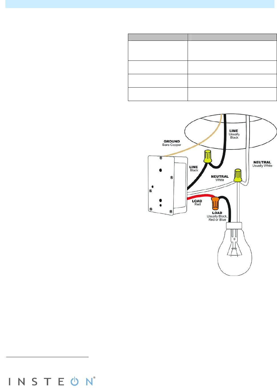
Wiring Diagram
NOTE: Home’s wire colors
and locations may vary
Installing In-LineLinc Dimmer Dual-Band
1) At electrical panel, turn off circuit breaker(s) and/or remove fuse(s) feeding wall box. Verify the power
is off.
2) Remove the fixture’s wallplate, unscrew the fixture and pull it out from the junction box.
3) Disconnect the wires from the fixture and
ensure that you have ½” of bare wire on
the ends.1
4) After ensuring wires are not touching, turn
breaker(s) back on.
5) Use a voltage meter to identify the Line
and Load wires connected to the fixture,
then identify Neutral and Ground wires.
6) Turn off breaker(s).
7) Connect wires according to the wiring
diagram below. Confirm there are firm
attachments with no exposed wire.
8) Prior to reinstalling the fixture, turn on circuit
breaker supplying power to the fixture.
9) Use In-LineLinc Dimmer Dual-Band’s ON and
OFF buttons to test load control.
10) Add In-LineLinc Dimmer Dual-Band to scene(s)
as a responder to desired INSTEON devices.
11) Turn off breaker(s).
12) Gently place In-LineLinc Dimmer Dual-Band into
the junction box, making sure nothing could
accidentally press any of the buttons on its face.
13) Reinstall the fixture.
14) Turn on breaker(s).
In-LineLinc Wire Wall Box Wires
Bare copper Ground
(commonly bare green wire or
green screw)
White Neutral
(commonly white wire bundle)
Red Load
(Light, etc.)
Black Line
(100 - 277V to Neutral)
Page 6 of 14 2475DA1 - Rev: 4/20/2012 4:35 PM
Using In-LineLinc Dimmer Dual-Band
LEDs
LED Meaning
Solid green Load is on (at any dim level)
Solid red Load is off
Blinking green Unit is in linking mode
Blinking red Unit is in unlinking mode
Fast blinking red and optional
blink-on-traffic is turned on
Dimmer is off and INSTEON traffic received
Fast blinking green and optional
blink-on-traffic is turned on
Dimmer is on and INSTEON traffic received
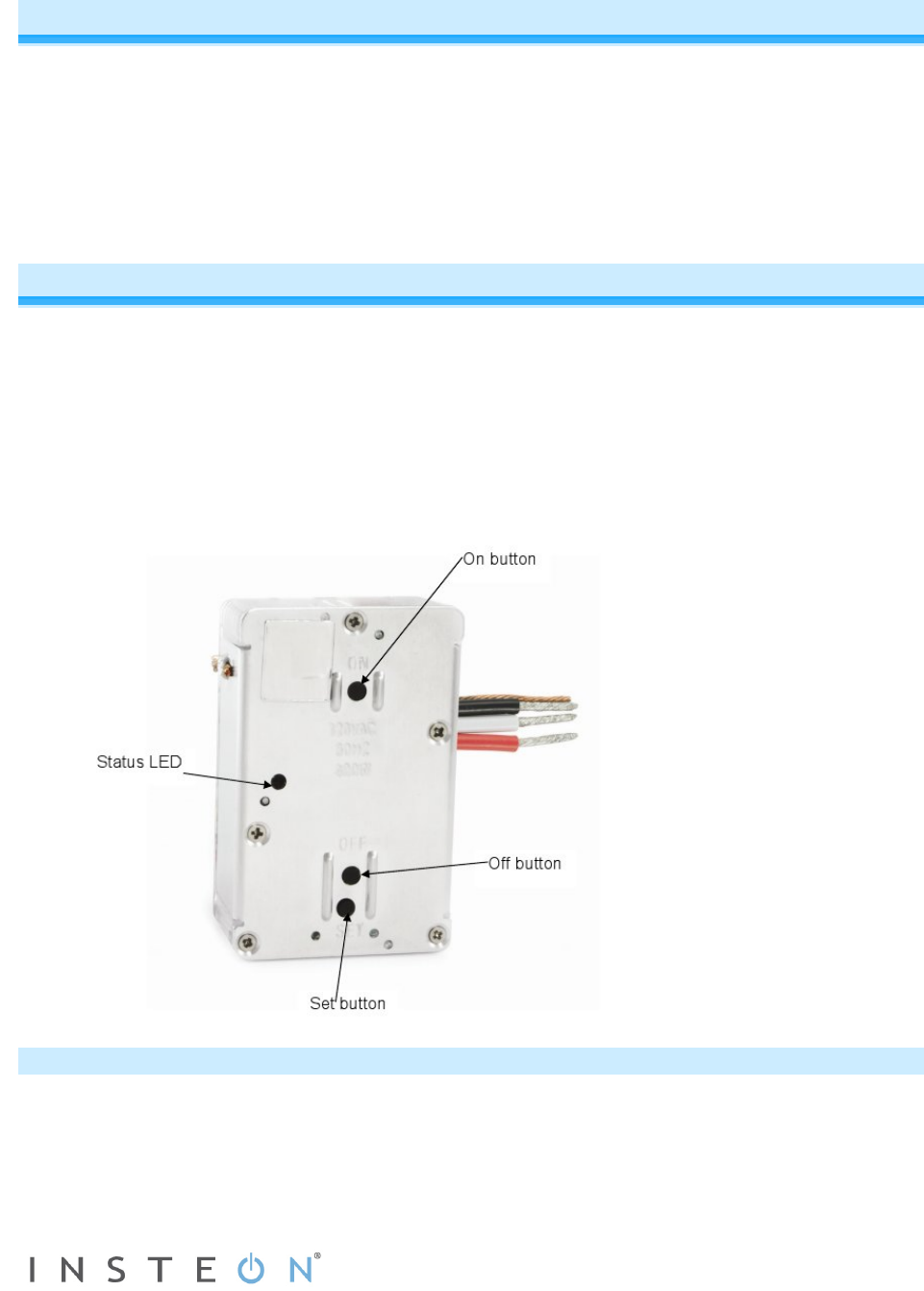
Using the ON and OFF Buttons
The small button switches allows you to test the load and functions prior to final installation.
- Tap ON button to make load turn on at local ramp rate to local on-level brightness
- Tap OFF button to make load turn off at local ramp rate to full-off
- Double-tap ON button to make load turn full-on quickly
- Double-tap OFF button to make load turn full-off quickly
- Press and hold ON button to gradually brighten load to full-on
- Press and hold OFF button to gradually dim load to full-off
Button Functions
Button Tap Double-Tap Press and Hold
ON Ramp to on-level Fast on Brighten
OFF Ramp to off Fast off Dim
Set Set the default
on-level Sets the default
ramp rate Starts linking
mode
Local On-Level
The local on-level is the brightness level at which the light(s) physically wired to In-LineLinc Dimmer Dual-
Band turn on. The default on-level is 100%, but it can be adjusted to any brightness level.
1) Use either ON or OFF buttons on In-LineLinc Dimmer Dual-Band to adjust light to desired brightness.
2) Tap the In-LineLinc Dimmer Dual-Band’s Set button.
SwitchLinc will beep.
3) Test on-level settings by tapping the ON/OFF buttons on In-LineLinc Dimmer Dual-Band.

Page 7 of 14 2475DA1 - Rev: 4/20/2012 4:35 PM
NOTE:
If In-LineLinc Dimmer Dual-Band’s Status LED is blinking, you held the Set button down too long and
accidentally placed it into linking mode, which times out after 4 minutes of inactivity. To manually exit
linking mode, tap any button except Set button.
Beeper Behavior
The In-LineLinc Dimmer Dual-Band features a built-in beeper which aids in programming and can also be
used as an indicator via compatible software controllers. Here are the different beeping behaviors and
what they mean:
- Single beep: Transition from one setup mode to another
- Double-beep: Successful link or unlink
- Continuous beeps for 3 seconds: unsuccessful link or 4-minute setup timeout
- Continuous beeps for 10 seconds: warning prior to a factory reset
Setting Up an INSTEON Scene
INSTEON remote control is done using scenes. Scenes allow you to instantly activate favorite lighting
and appliance settings at the touch of a button (or in response to a command from a central controller or
sensor). Each scene has at least one controller and at least one responder linked to one another. Simple
scenes can be set up using the instructions below. Software such as HouseLinc is recommended for
setup of larger scenes.
Adding In-LineLinc Dimmer Dual-Band to a Scene as an INSTEON Responder
1) Use the ON/OFF buttons on In-LineLinc Dimmer Dual-Band to adjust the load to the state you wish to
activate from the controller .
2) Press and hold the scene controller button until it beeps.1
Controller’s LED will blink.
3) Press and hold the Set button on In-LineLinc Dimmer Dual-Band until it double-beeps.
Controller will double-beep2 and its LED will stop blinking.
4) Confirm that scene addition was successful by toggling the controller’s scene button on and off.
Light should go to the level you defined in step 2.
Removing In-LineLinc Dimmer Dual-Band from a Scene as an INSTEON Responder
If you are going to uninstall In-LineLinc Dimmer Dual-Band, it is very important that you remove it from all
of its scene controllers. Otherwise, controllers will experience delays and may produce flashing error
indications.
1) Press and hold controller’s scene button until controller beeps.3
Controller’s LED will blink.
2) Press and hold Controller’s scene button until controller beeps again.3
Controller’s LED will continue blinking.
3) Press and hold Set button on In-LineLinc Dimmer Dual-Band until it double-beeps.
Controller will double-beep2 and its LED will stop blinking.
4) Confirm scene removal was successful by tapping the button on the controller with the scene you just
removed.
In-LineLinc Dimmer Dual-Band will no longer respond.
1 If the controller does not have a beeper, wait until its LED begins blinking
2 Most models
3 For devices without beepers hold until its LED begins blinking (this may take 10+ seconds)

Page 8 of 14 2475DA1 - Rev: 4/20/2012 4:35 PM
Advanced Features
Using In-LineLinc Dimmer Dual-Band as a Phase Bridge
In-LineLinc Dimmer Dual-Band automatically bridges the electrical phases in your home to allow
powerline-only INSTEON devices to communicate with RF-only INSTEON devices. If you are relying on
In-LineLinc Dimmer Dual-Band to bridge the building’s electrical phases, use the following procedure to
activate phase bridging detection mode:
1) Start phase bridging detection mode by tapping In-LineLinc Dimmer Dual-Band’s Set button four
times quickly.
In-LineLinc Dimmer Dual-Band will begin beeping and setup LED will be solid green.
2) Check the LED behavior of the “other” dual-band devices.
a) If it is blinking green, it is within range and not on the same electrical phase. Go to step 3.
b) If it is not blinking green, try moving the device, check other devices or begin the test from a
different device.
3) Tap In-LineLinc Dimmer Dual-Band’s Set Button.
In-LineLinc Dimmer Dual-Band stops beeping and LED returns to previous state.
Other devices’ LEDs will stop blinking in a few seconds.
Power Restoration
In-LineLinc Dimmer Dual-Band stores all of its scenes, properties, etc. in its internal non-volatile memory.
As such, all settings are retained after a power outage. Upon power restoration, In-LineLinc Dimmer Dual-
Band will return its connected load and all LEDs to their states prior to power outage.
X10 Programming
Instructions on setting X10 primary address and scene addresses can be found online at
http://www.smarthome.com/insteon-x10-programming.html.
Factory Reset
Factory Reset clears all user settings from In-LineLinc Dimmer Dual-Band including INSTEON Scenes,
On-Levels, Ramp Rates, X10 addresses, etc.
Option 1
1) If possible, remove all scene memberships prior to performing the factory reset.
2) Press and hold Set button on In-LineLinc Dimmer Dual-Band until it beeps.
LED will blink green.
3) Press and hold In-LineLinc Dimmer Dual-Band’s Set button until it beeps again.
In-LineLinc Dimmer Dual-Band’s LED will blink red.
4) Double-tap the Set button, then immediately press and hold it until the long beep stops.
In-LineLinc Dimmer Dual-Band will emit a long beep and its LED will turn off.
The connected load will turn on.
Option 2 – partner required
1) If possible, remove all scene memberships prior to performing the factory reset.
2) Turn off circuit breaker.
3) While pressing and holding In-LineLinc Dimmer Dual-Band’s Set button (do not let go), have a partner
turn on the circuit breaker.
As you continue to press and hold, In-LineLinc Dimmer Dual-Band will emit a long beep.
4) Continue to press and hold Set button until long beep stops, then release.
As soon as you release Set button, In-LineLinc Dimmer Dual-Band LED will turn on.

Page 9 of 14 2475DA1 - Rev: 4/20/2012 4:35 PM
After a few seconds, In-LineLinc Dimmer Dual-Band will double-beep.
The connected load will turn on.
Local Ramp Rate
The local ramp rate is the time it takes for the light(s) physically wired to In-LineLinc Dimmer Dual-Band to
brighten from off to 100% brightness and vice versa. The default ramp rate is 0.5 seconds, but it is
adjustable from 0.1 seconds to 9 seconds locally or up to 8 minutes using software such as HouseLinc.
Ramp rate is determined using the brightness level of the load. Refer to the chart below to determine the
ramping speed based on the load brightness.
Brightness Level Ramp Rate in
Seconds
90-100% 0.1
77-87% 0.2
65-74% 0.3
52-61% 2.0
39-48% 2.0
26-35% 4.5
13-23% 6.5
1-10% 8.5
1% 9.0
1) Adjust the connected light(s) to the brightness level corresponding to desired ramp rate.
2) Double-tap In-LineLinc Dimmer Dual-Band’s Set button.
In-LineLinc Dimmer Dual-Band will double-beep.
3) Test the ramp rate settings by tapping the ON/OFF buttons.
The connected light(s) will brighten and dim at the new rate.
4) If your double-tap was not fast enough, you may have accidentally changed the local on-level instead
of the local ramp rate. (Note: software such as HouseLinc allows you to remotely set on-levels and
ramp rates exactly as desired and consistently around the house.)
Page 10 of 14 2475DA1 - Rev: 4/20/2012 4:35 PM
Specifications
General
Product name In-LineLinc Dimmer Dual-Band – INSTEON Remote
Control In-Line Dimmer (Dual-Band)
Brand INSTEON
Manufacturer product number 2475DA1
UPC 813922012361
FCC ID SBP2475DA1
Patent number 7,345,998; protected under U.S. and foreign patents
(see www.insteon.com )
Warranty 2 years, limited
INSTEON
INSTEON I.D. 1
INSTEON 400 responder groups and 1 controller group
Maximum scene memberships 400 (combined controller and responder)
On Off
Fast on Fast off
Scene commands supported
as responder
Brighten Dim
Software configurable Yes, always
RF range 100’ open air
X10 support Yes
X10 addresses 1 max, unassigned by default
Page 11 of 14 2475DA1 - Rev: 4/20/2012 4:35 PM
INSTEON device category 0x01
INSTEON device subcategory 0x32
Mechanical
Mounting Mounts inside standard electrical box in the ceiling
or in the wall
Wires
Colors:
White – Neutral 18-gauge
Black – Hot 16-gauge
Red – Load 16-gauge
Copper – Earth ground 16-gauge
Set button 1
Beeper Yes
LED Dual-color green and red
Dimensions 2.75" H x 1.75" W x 0.88" D
Weight 120 grams / 0.26 pounds
Operating environment Indoors
Operating temperature range 32 - 104 degrees Fahrenheit
(0 – 40 degrees Celsius)
Operating humidity range 0-90% relative humidity, non-condensing
Storage conditions 4F to +158F (-20 – 70 degrees Celsius)
Electrical
Voltage 100 to 277VAC (+/- 10%)
Frequency 50/60Hz (+/- 5%) Auto Detected at power-up

Page 12 of 14 2475DA1 - Rev: 4/20/2012 4:35 PM
Maximum load 400 Watts
Load type(s) Wired-in incandescent lighting
Retains all settings without
power Yes, all saved in Non-volatile EEPROM
Standby power consumption < 1 watt
Safety approved ETL (Intertek Testing Services)
Certifications FCC, IC Canada
Page 13 of 14 2475DA1 - Rev: 4/20/2012 4:35 PM
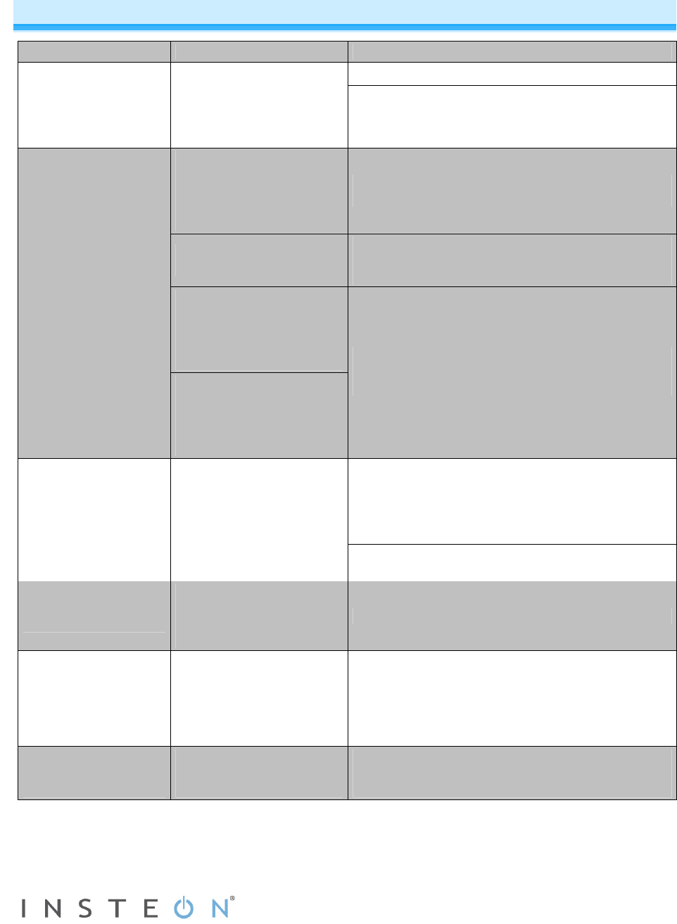
Troubleshooting
Problem Possible Cause Solution
Make sure the circuit breaker is turned on.
In-LineLinc Dimmer
Dual-Band won’t
control the load and
the Status LED is not
turning on.
In-LineLinc Dimmer Dual-
Band may not be getting
power.
Check the junction box wires to ensure all
connections are tight and no bare wires are
exposed.
The controller might have
been reset without
removing In-LineLinc
Dimmer Dual-Band from a
scene.
Re-add In-LineLinc Dimmer Dual-Band to the
controller.
The INSTEON signal may
be too weak.
Add additional INSTEON devices or move around
existing INSTEON devices. All INSTEON devices
act as INSTEON network repeaters
Large appliances such as
refrigerators or air
conditioners may be
producing electrical noise
on the powerline.
In-LineLinc Dimmer
Dual-Band won’t add
to a scene or respond
to a controller.
Other electrical devices,
such as computers,
televisions, or power
strips, may be absorbing
the INSTEON signal.
Install a powerline noise filter (FilterLinc #1626-10)
to filter electrical noise and minimize signal
attenuation.
Remove any unused responders from the
controller.
HINT: If you are using home automation software
such as HouseLinc, you can easily check scene
membership and eliminate any unnecessary links.
In-LineLinc Dimmer
Dual-Band is taking a
long time to respond
to a controller.
The controller may be
sending commands to a
responder that is no
longer in use. Commands
for the unused responder
are being resent and
loading down the signal. If the above doesn’t work, perform a factory reset
on the controller.
The load turned on by
itself.
Another controller or timer
could have triggered In-
LineLinc Dimmer Dual-
Band.
Perform a factory reset. See Factory Reset.
The controller can turn
off In-LineLinc Dimmer
Dual-Band but it
doesn’t turn on.
In-LineLinc Dimmer Dual-
Band may be added to a
scene at its off state.
Re-add In-LineLinc Dimmer Dual-Band to a scene
on the controller while the load is on. See Adding
In-LineLinc Dimmer Dual-Band to a Scene as an
INSTEON Responder.
In-LineLinc Dimmer
Dual-Band is locked
up.
A surge or excessive
noise on the powerline
may have glitched it.
Temporarily remove power from In-LineLinc
Dimmer Dual-Band, usually by opening the
breaker feeding it.
If you have tried these solutions, reviewed this manual and still cannot resolve an issue you are having
with In-LineLinc Dimmer Dual-Band, please call the INSTEON Support Line at 800-762-7845.

Page 14 of 14 2475DA1 - Rev: 4/20/2012 4:35 PM
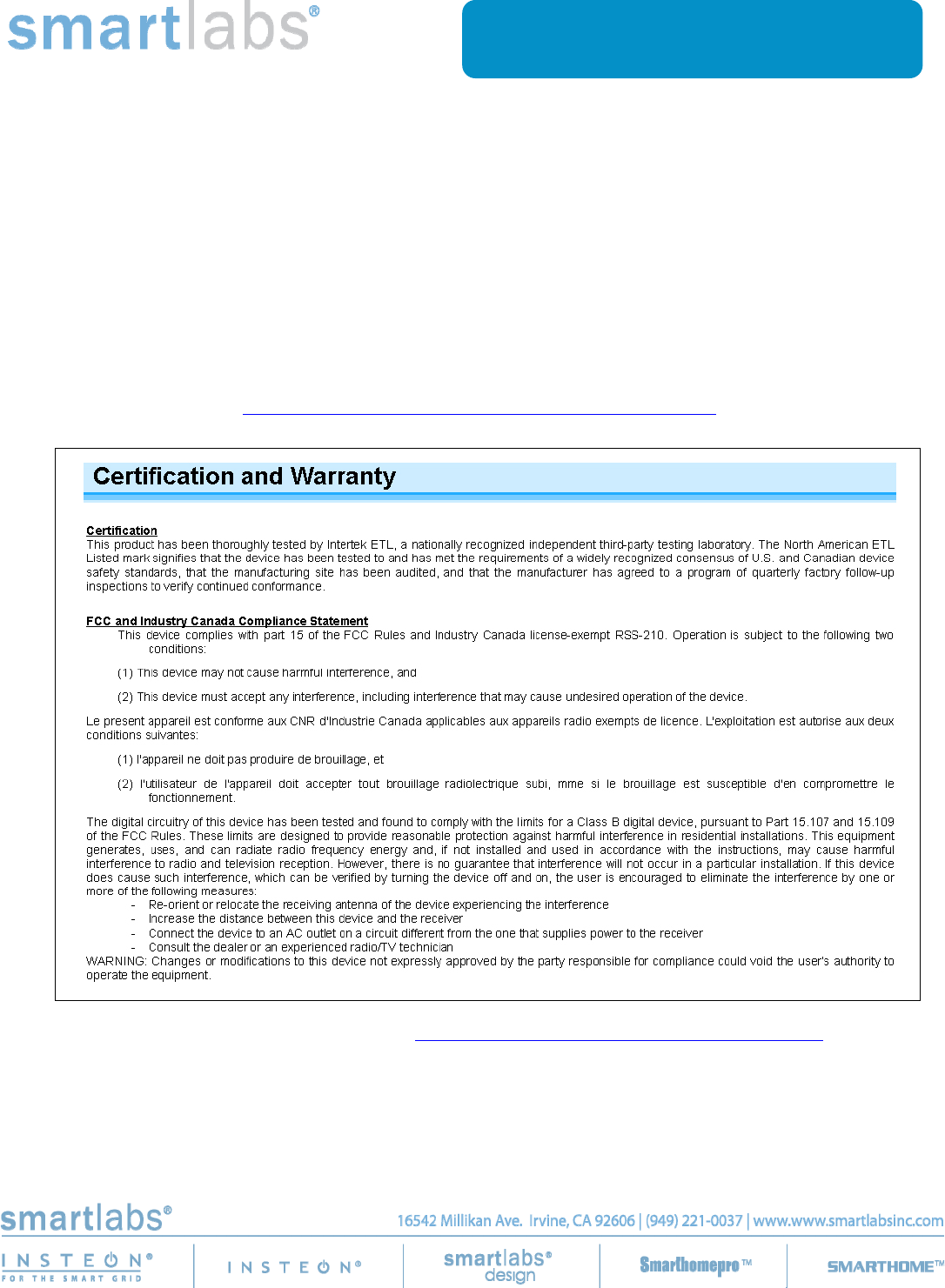
Certification and Warranty
Certification
This product has been thoroughly tested by Intertek ETL, a nationally recognized independent third-party testing laboratory. The North American ETL
Listed mark signifies that the device has been tested to and has met the requirements of a widely recognized consensus of U.S. and Canadian device
safety standards, that the manufacturing site has been audited, and that the manufacturer has agreed to a program of quarterly factory follow-up
inspections to verify continued conformance.
FCC and Industry Canada Compliance Statement
This device complies with part 15 of the FCC Rules and Industry Canada license-exempt RSS-210. Operation is subject to the following two
conditions:
(1) This device may not cause harmful interference, and
(2) This device must accept any interference, including interference that may cause undesired operation of the device.
Le present appareil est conforme aux CNR d'Industrie Canada applicables aux appareils radio exempts de licence. L'exploitation est autorise aux deux
conditions suivantes:
(1) l'appareil ne doit pas produire de brouillage, et
(2) l'utilisateur de l'appareil doit accepter tout brouillage radiolectrique subi, mme si le brouillage est susceptible d'en compromettre le
fonctionnement.
The digital circuitry of this device has been tested and found to comply with the limits for a Class B digital device, pursuant to Part 15.107 and 15.109
of the FCC Rules. These limits are designed to provide reasonable protection against harmful interference in residential installations. This equipment
generates, uses, and can radiate radio frequency energy and, if not installed and used in accordance with the instructions, may cause harmful
interference to radio and television reception. However, there is no guarantee that interference will not occur in a particular installation. If this device
does cause such interference, which can be verified by turning the device off and on, the user is encouraged to eliminate the interference by one or
more of the following measures:
- Re-orient or relocate the receiving antenna of the device experiencing the interference
- Increase the distance between this device and the receiver
- Connect the device to an AC outlet on a circuit different from the one that supplies power to the receiver
- Consult the dealer or an experienced radio/TV technician
WARNING: Changes or modifications to this device not expressly approved by the party responsible for compliance could void the user’s authority to
operate the equipment.
Limited Warranty
Seller warrants to the original consumer purchaser of this product that, for a period of two years from the date of purchase, this product will be free
from defects in material and workmanship and will perform in substantial conformity to the description of the product in this Owner’s Manual. This
warranty shall not apply to defects or errors caused by misuse or neglect. If the product is found to be defective in material or workmanship, or if the
product does not perform as warranted above during the warranty period, Seller will either repair it, replace it, or refund the purchase price, at its
option, upon receipt of the product at the address below, postage prepaid, with proof of the date of purchase and an explanation of the defect or error.
The repair, replacement, or refund that is provided for above shall be the full extent of Seller’s liability with respect to this product. For repair or
replacement during the warranty period, call the INSTEON Gold Support Line at 800-762-7845 with the Model # and Revision # of the device to receive
an RMA# and send the product, along with all other required materials to:
INSTEON
ATTN: Receiving
16542 Millikan Ave.
Irvine, CA 92606-5027
Limitations
The above warranty is in lieu of and Seller disclaims all other warranties, whether oral or written, express or implied, including any warranty or
merchantability or fitness for a particular purpose. Any implied warranty, including any warranty of merchantability or fitness for a particular purpose,
which may not be disclaimed or supplanted as provided above shall be limited to the two-year of the express warranty above. No other representation
or claim of any nature by any person shall be binding upon Seller or modify the terms of the above warranty and disclaimer.
Home automation devices have the risk of failure to operate, incorrect operation, or electrical or mechanical tampering. For optimal use, manually verify
the device state. Any home automation device should be viewed as a convenience, but not as a sole method for controlling your home.
In no event shall Seller be liable for special, incidental, consequential, or other damages resulting from possession or use of this device, including
without limitation damage to property and, to the extent permitted by law, personal injury, even if Seller knew or should have known of the possibility of
such damages. Some states do not allow limitations on how long an implied warranty lasts and/or the exclusion or limitation of damages, in which case
the above limitations and/or exclusions may not apply to you. You may also have other legal rights that may vary from state to state.
Protected under U.S. and foreign patents (see www.insteon.com )
© Copyright 2012 INSTEON, 16542 Millikan Ave., Irvine, CA 92606, 800-762-7845, www.insteon.com