SmartLabs 4773 120-277V Heavy-Duty RF InLine Switch User Manual 4773 QSG 20110429
SmartLabs, Inc. 120-277V Heavy-Duty RF InLine Switch 4773 QSG 20110429
Contents
- 1. Owners Manual
- 2. Users Manual
Users Manual
Page 1 of 1
Rev. 04-29-2011
SMART Limited Warranty – SMART warrants to original consumer of this product for a period of 2 years from date of purchase, this product will be free from
defects in material & workmanship & will perform in substantial conformity with its Installation and Programming Guide. Warranty shall not apply to defects
caused by misuse or neglect.
U.S. Patent No. 7,345,998, International patents pending © Copyright 2011
SMART, 16542 Millikan Ave., Irvine, CA 92606, 866-883-9220
*Setup Modes will automatically time out after 4 minutes.
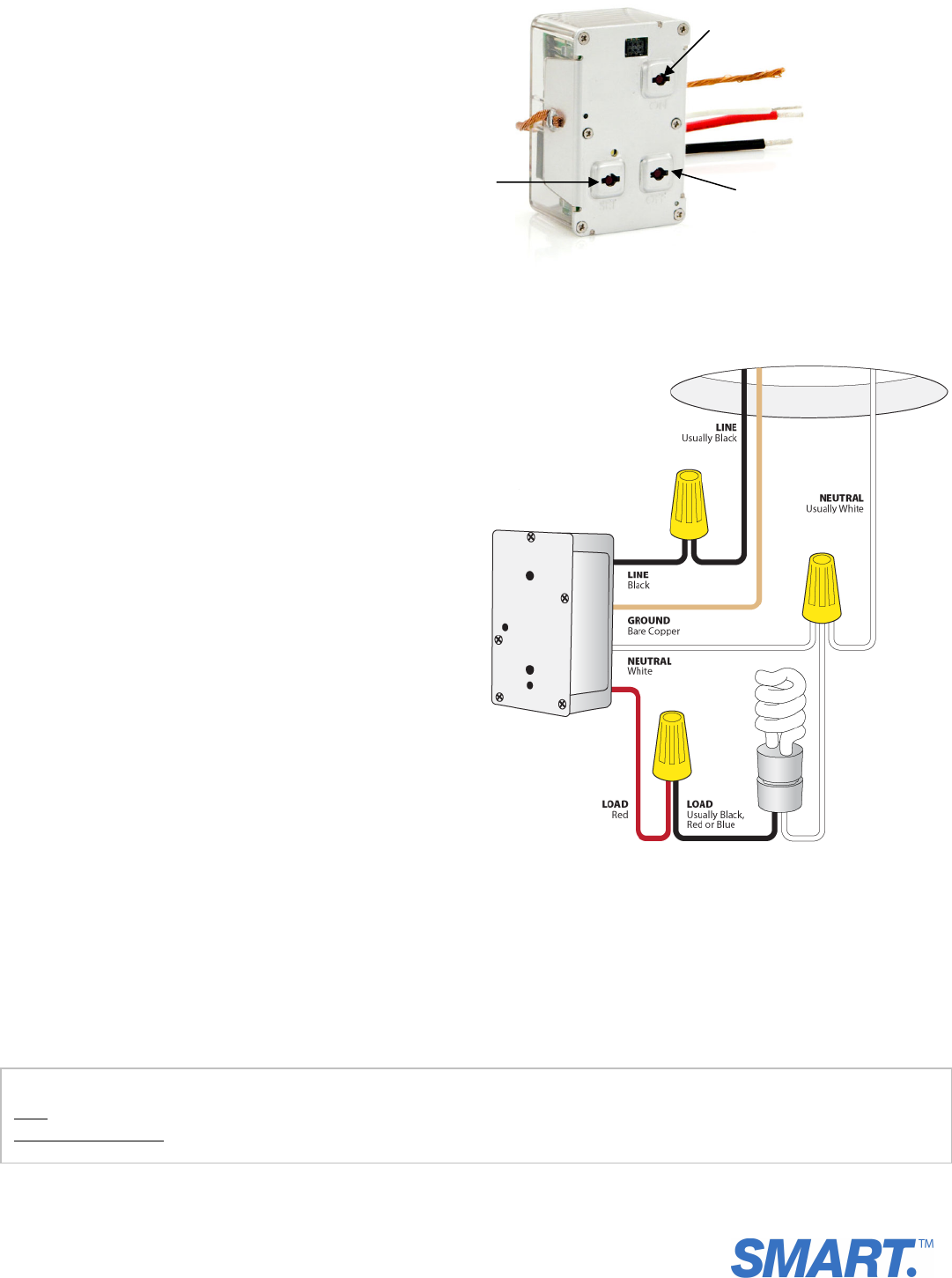
Wiring Diagram
NOTE: Home’s wire color and wire location may vary
Figure 1
Installation
1) Be sure to write down the INSTEON ID and location of
the fixture you’ll be controlling (e.g., 01.F7.G5, Mike’s
bedroom light)
2) At the circuit breaker or fuse panel, disable the circuit
supplying power to the fixture
3) Remove the wallplate from the fixture you are replacing.
Then, unscrew the fixture itself and pull it out from the
junction box.
4) Disconnect the wires from the fixture you will be
controlling and ensure you have 1/2” of bare wire on the
ends. If the wires cannot be detached by unscrewing
them, cut the wires where they enter the switch and
then strip ½ inch of insulation off the ends.
5) See Figure 1 to identify and connect the LINE, LOAD,
NEUTRAL, and GROUND wires on In-Line Switch. Be sure
you have correctly identified the wires in the junction
box before connecting them.
6) After you have connected all the wires, ensure that the
wire connectors are firmly attached and that there is no
exposed copper except for the GROUND wire
7) Prior to reinstalling the fixture, enable power to the
fixture from the circuit breaker or fuse panel
8) Use the On/Off buttons to test that the module is
working and controlling the load
9) Link In-Line Switch to the desired INSTEON Controllers:
a. Set the Controller to Linking Mode.* (For most
Controllers, press & hold an On or Scene button
for 10 seconds or the Set button for 3 seconds.)
b. Press & hold the Set button on In-Line Switch
until it double-beeps (3 seconds)
The In-Line Switch Status LED will flash once
and then turn on solid if the load is off or turn
off if the load is on
c. Confirm that Linking was successful by tapping
the button you just Linked to on the Controller
In-Line Switch will respond appropriately
10) Gently place In-Line Switch into the junction box,
making sure that nothing could accidentally be pressing
any of the buttons on its face
11) Reinstall the fixture
Quic
k
-Start Guide
In-Line Switch, 277V
Model: 4773
Tools Needed
• Phillips screwdriver
• Wire cutter / stripper
• Voltage tester
• Non-conductive probe
Complete Instructions, Troubleshooting, and Tech Support
Call: Tech. Support @ 866-883-9220
Contact Us Online: www.smartproline.com
Set button
On button
Of
f
button