SmartLabs MM01 Micro Module User Manual Dimmer
SmartLabs, Inc. Micro Module Users Manual Dimmer
UserManual.wiki
>
SmartLabs
>
MM01 User Manual
>
Users Manual Dimmer
Contents
1.
Users Manual Dimmer
2.
Users Manual Relay
3.
Users Manual Shutter
4.
Users Manual 1
5.
Users Manual 2
6.
Users Manual 3
7.
Users Manual 4
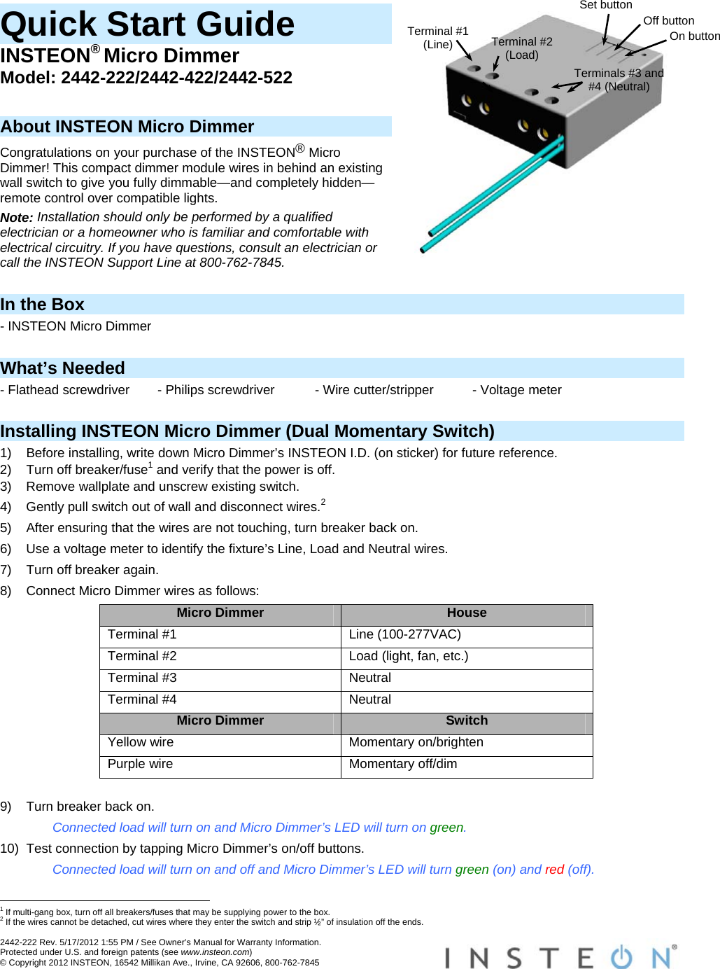
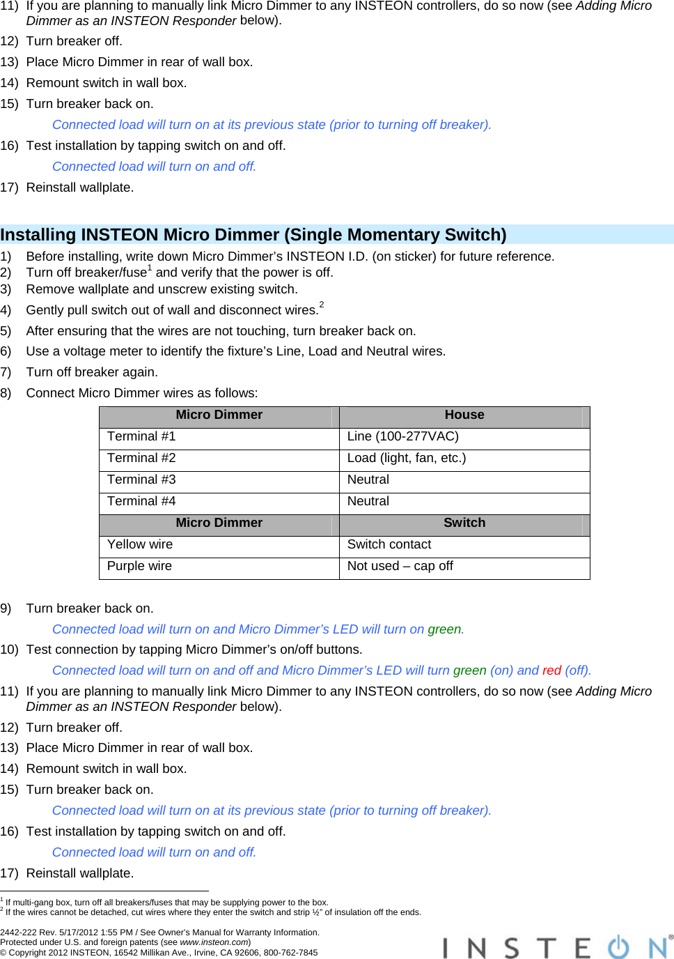
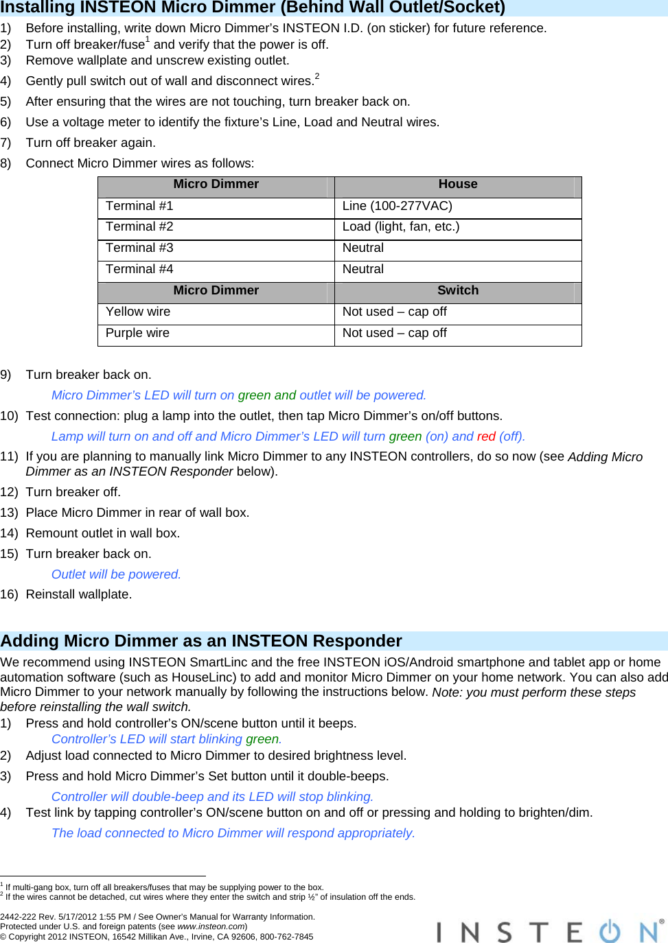
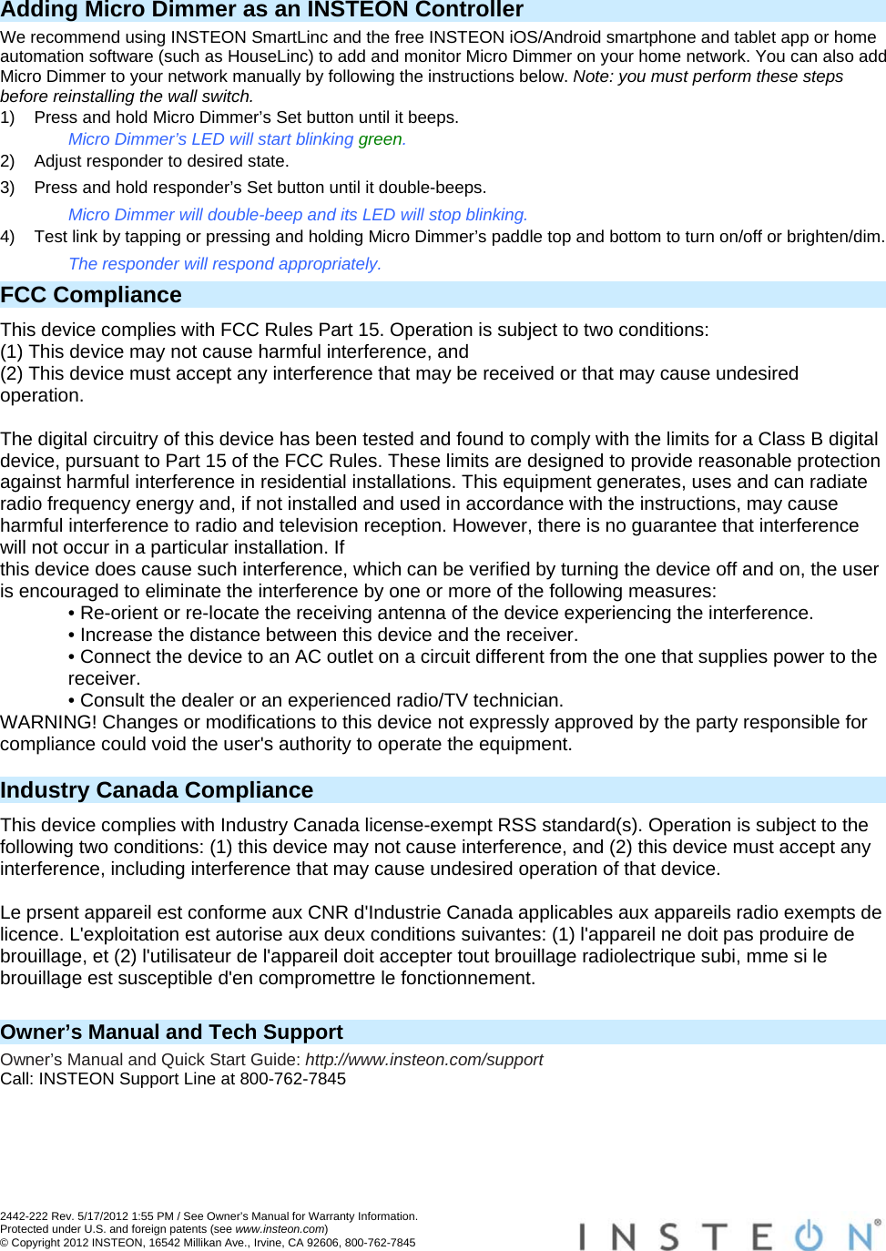
Users Manual Dimmer
Navigation menu
Upload a User Manual
Namespaces
Wiki Guide
HTML
PDF
Info
Views
User Manual
Discussion / Help
Navigation