SmartSight Networks S1000 S1000 User Manual S1000
SmartSight Networks Inc S1000 S1000
UserManual.wiki
>
SmartSight Networks
>
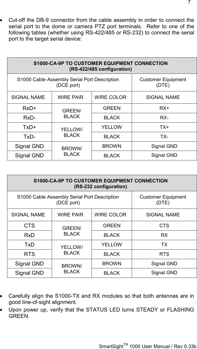
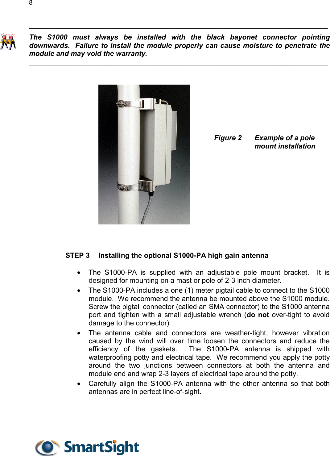
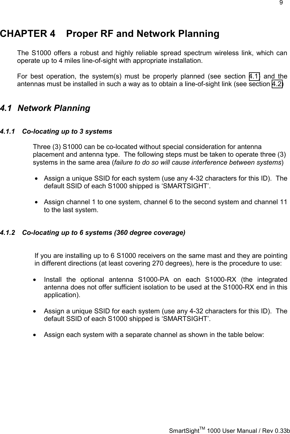
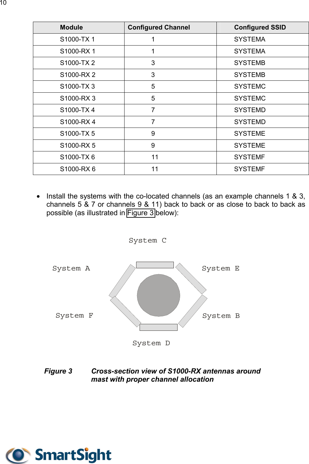
S1000 User Manual
>
Revised users manual
Contents
1.
Users manual
2.
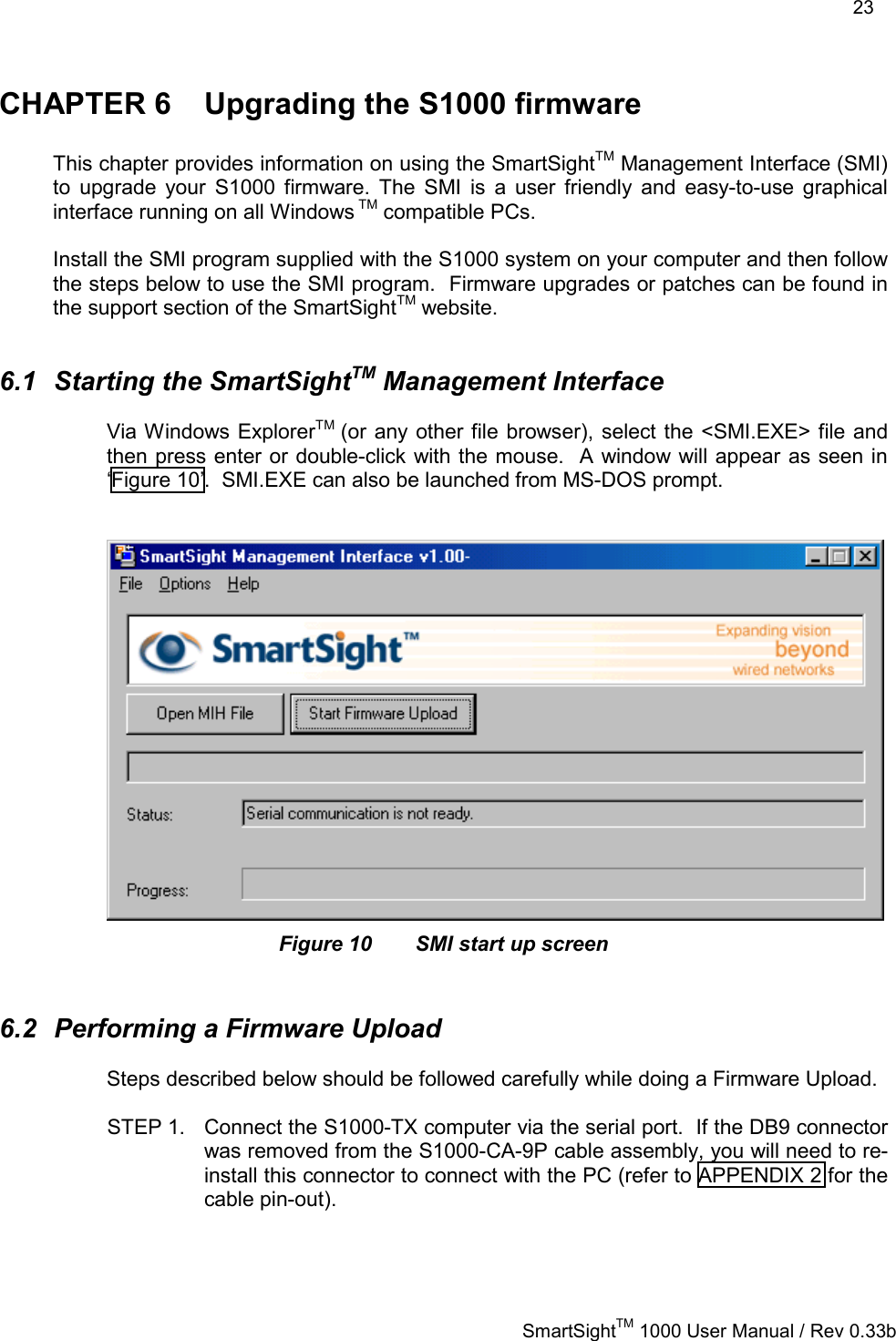
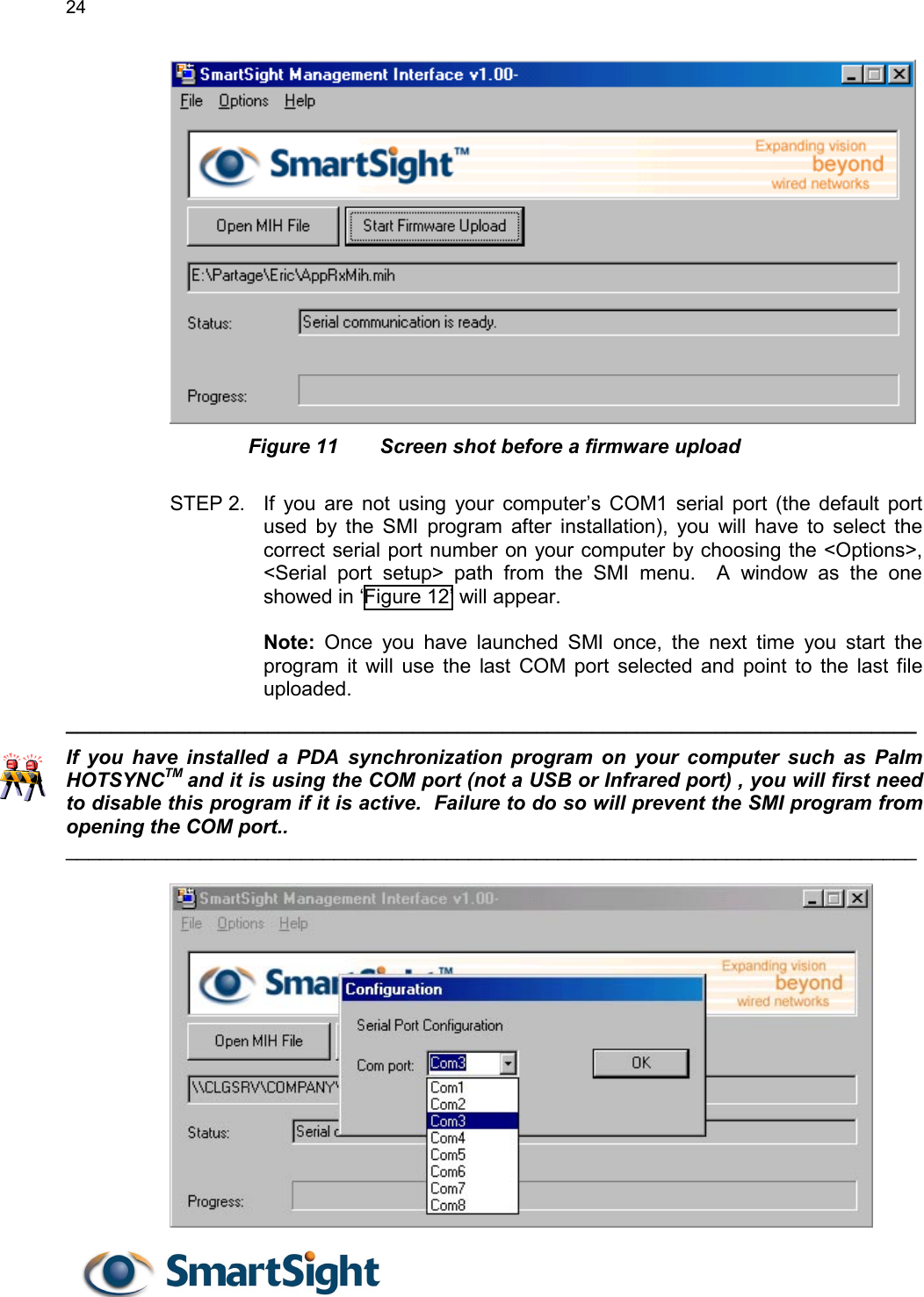
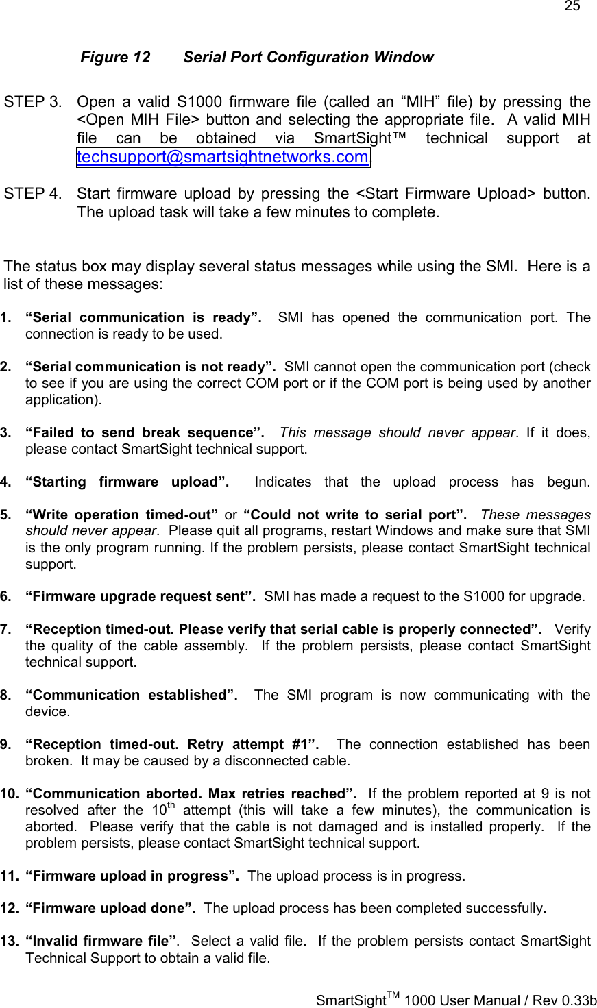
Revised users manual
Revised users manual
Navigation menu
Upload a User Manual
Namespaces
Wiki Guide
HTML
PDF
Info
Views
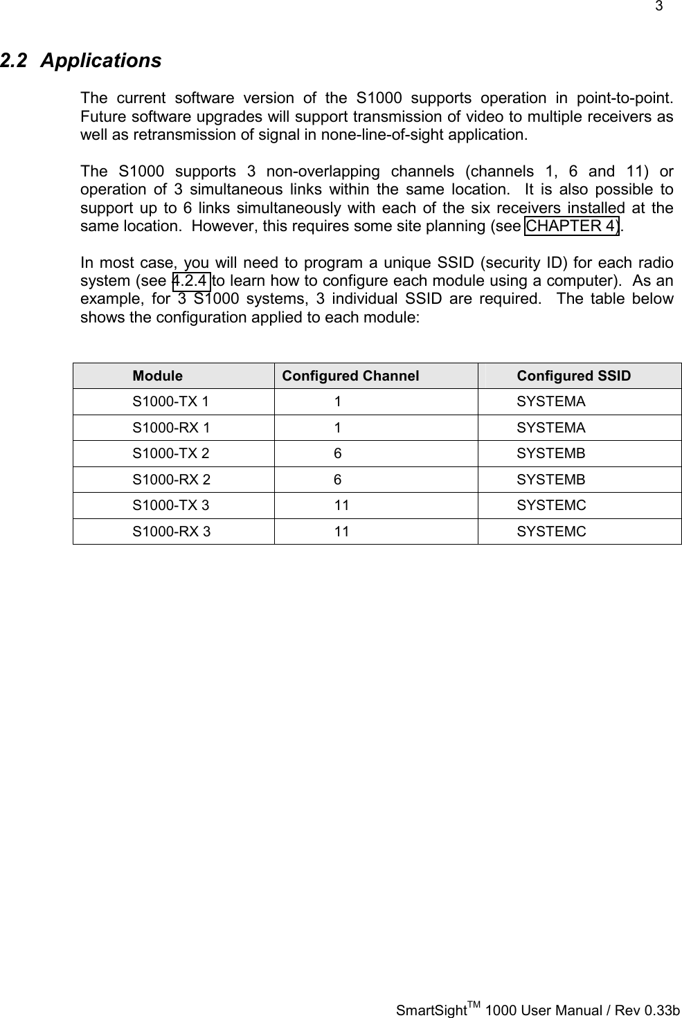
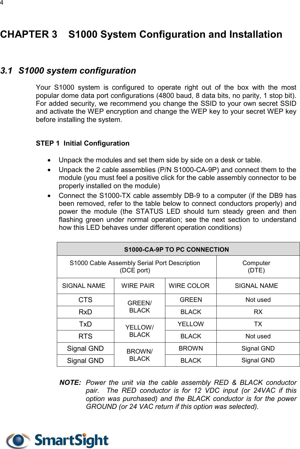
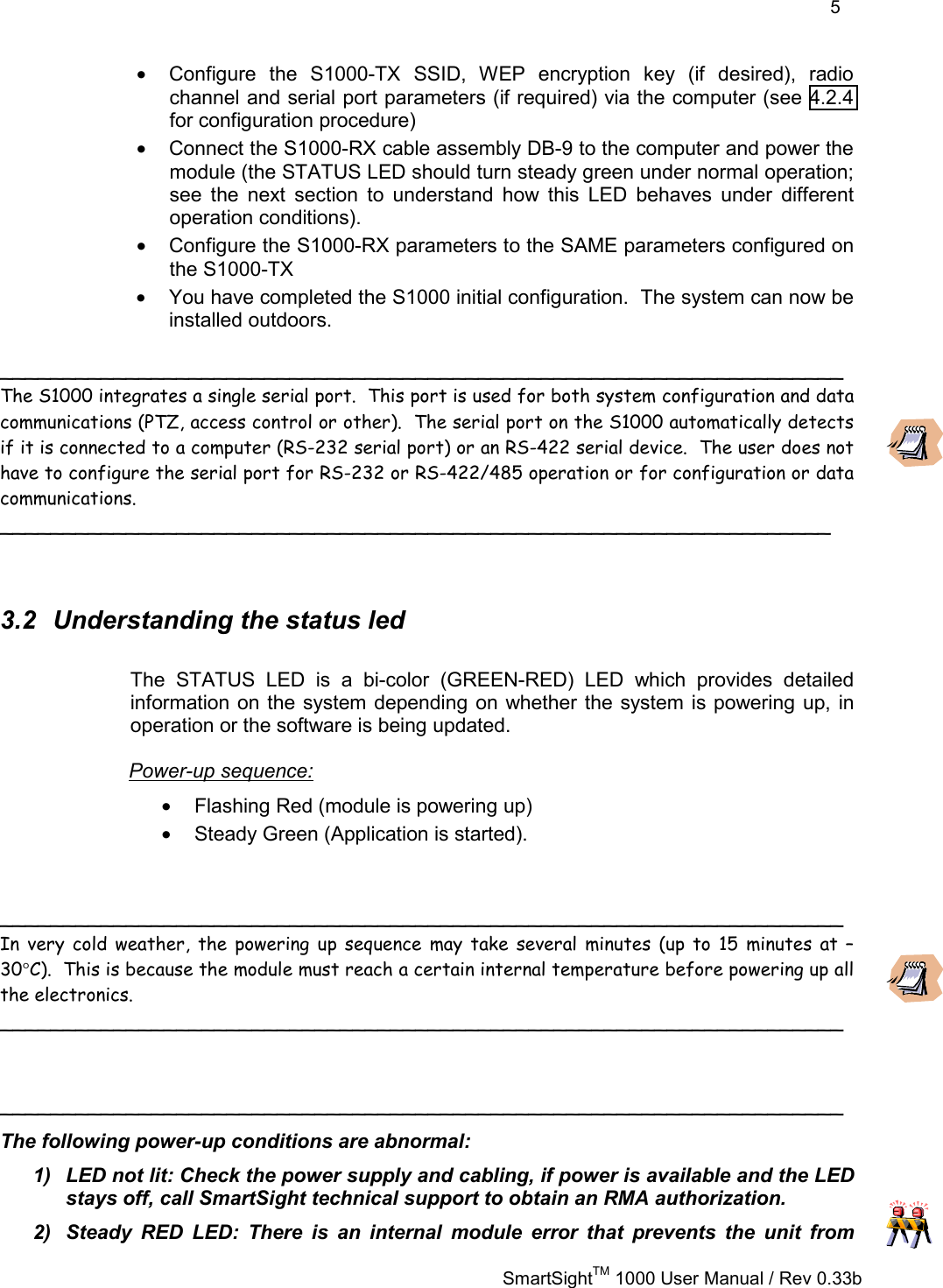
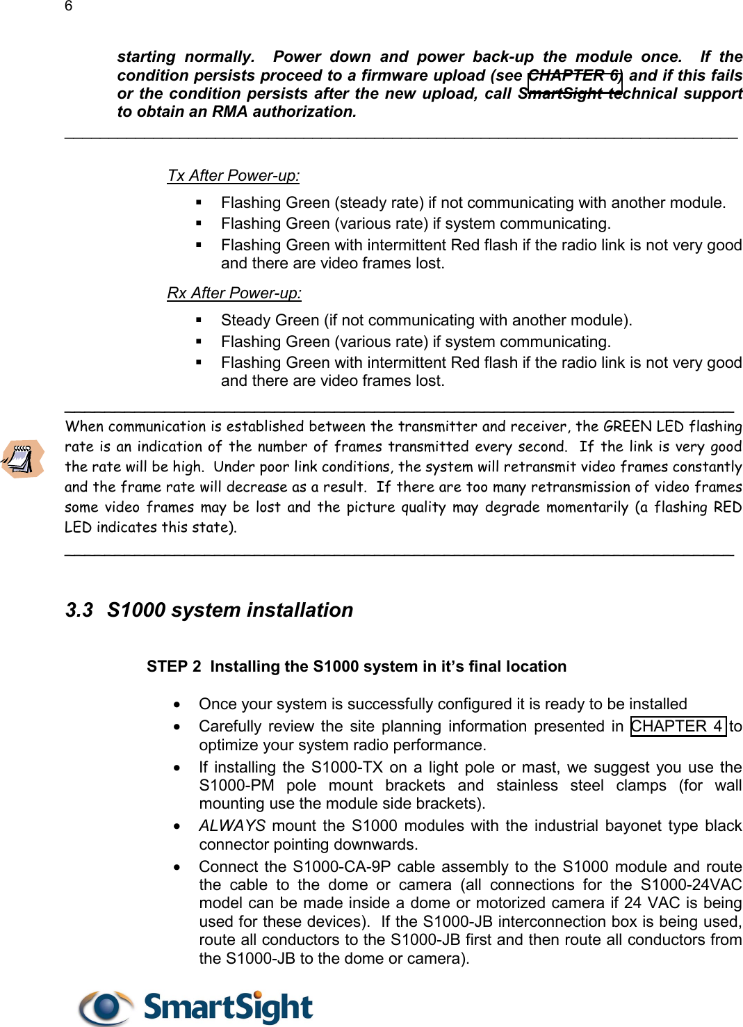
User Manual
Discussion / Help
Navigation