SmartSight Networks S1000 S1000 User Manual S1000
SmartSight Networks Inc S1000 S1000
Contents
- 1. Users manual
- 2. Revised users manual
Revised users manual


ii
INFORMATION TO USER
This device complies with Part 15 of the FCC (Federal Communications Commission)
Rules (see http://www.fcc.gov/). Operation is subject to the following two conditions: (1)
This device may not cause harmful interference, and (2) This device must accept any
interference received, including interference that may cause undesired operation.
This equipment has been tested and found to comply with the limits for Class B Digital
Device, pursuant to Part 15 of the FCC Rules. These limits are designed to provide
reasonable protection against harmful interference in residential installation. This
equipment generates and can radiate radio frequency energy and, if not installed and used
in accordance with the instructions, may cause harmful interference to radio
communications. However, there is no guarantee that interference will not occur in a
particular installation. If this equipment does cause harmful interference to radio or
television reception, which can be determined by turning the equipment off and on, the
user is encouraged to try to correct the interference by one or more of the following
measures:
• Reorient or relocate the receiving antenna
• Increase the separation between the equipment and S1000 module
• Connect the equipment into an outlet on a circuit different from that to which the
Receiver is connected
• Consult the dealer or an experienced radio/TV technician for help
Any changes or modifications not expressly approved by SmartSight Networks could void
the user’s authority to operate the equipment.
SMARTSIGHT is a trademark of SmartSight Networks, Inc.
Copyright © 2001 SmartSight Networks, inc., Laval, Quebec, -All rights reserved.
iii
SmartSightTM 1000 User Manual / Rev 0.33b
WARRANTY
Each standard product manufactured by SmartSight™ Networks is warranted to meet all
published specifications and to be free from defects in material and workmanship for a
period of one (1) year from date of delivery as evidenced by SmartSight™ Networks
packing slip or other transportation receipt. Products showing damage by misuse,
abnormal conditions of operation or products which have been modified by Buyer or have
been repaired or altered outside SmartSight™ Networks factory without a specific
authorization from SmartSight™ Networks shall be excluded from this warranty.
SmartSight™ Networks shall in no event be responsible for incidental or consequential
damages including without limitation, personal injury or property damage.
SmartSight™ Networks responsibility under this warranty shall be to repair or replace, at
its option, defective work or parts returned to SmartSight™ Networks with transportation
charges to SmartSight™ Networks factory paid by Buyer and return paid by SmartSight™
Networks. If SmartSight™ Networks determines that the Product is not defective within
the terms of the warranty, Buyer shall pay all costs of handling and transportation.
SmartSight™ Networks may, at its option, elect to correct any warranty defects by sending
its supervisory or technical representative, at SmartSight™ Networks expense, to
customer’s plant or location. SmartSight™ Networks shall in no event be responsible for
incidental or consequential damages including, without limitation, personal injury or
property damage.
SINCE SMARTSIGHT™ NETWORKS HAS NO CONTROL OVER CONDITIONS OF
USE, NO WARRANTY IS MADE OR IMPLIED AS TO SUITABILITY FOR CUSTOMER’S
INTENDED USE. THERE ARE NO WARRANTIES, EXPRESSED OR IMPLIED,
EXCEPT AS STATED HEREIN. This limitation on warranties shall not be modified by
verbal representations.
Equipment shipped EX-Works SmartSight™ Networks factory shall become the property
of Buyer, upon transfer to the common carrier. Buyer shall communicate directly with the
carrier by immediately requesting carrier’s inspection upon evidence of damage in
shipment.
Buyer must obtain a Return Materials Authorization (RMA) number and shipping
instructions from SmartSight™ Networks prior to returning any Product under warranty.
DO NOT RETURN ANY SMARTSIGHT™ NETWORKS PRODUCT TO THE FACTORY
UNTIL RMA AND SHIPPING INSTRUCTIONS ARE RECEIVED.
iv
Customer Support
If after reading this manual, you encounter any trouble installing or using any
SmartSight™ product, please contact your local distributor or SmartSight representative.
If problems are not solved, we will be glad to assist you directly. You can call
SmartSight™ Networks Customer Service for assistance during normal business hours.
The fax and phone numbers are:
Ph: 450-686-9000 (Canada) and 888-494-7337 (North America)
Fax: 450-686-0198
You may also e-mail your inquiries and comments at the following address:
techsupport@smartsightnetworks.com
About this User Manual
This User’s Manual covers the information and procedures on installing, configuring and
using the SmartSight™ 1000 modules. This manual is also a reference for persons who
must perform or coordinate tasks associated with programming and managing the
SmartSight™ 1000 system.
Pan-Tilt-Zoom functions to be controlled through the use of a 3rd party keyboard shall not
be discussed in this manual. While this user manual will give detailed information on how
to configure the SmartSight™ 1000 for use with any keyboard/PTZ (Pan-Tilt-Zoom)
platform, knowledge of the setup of these keyboard/PTZ platforms remains the
responsibility of the end user.
Prerequisite Knowledge
Throughout the user's manual there are explanations and procedures that presume
working familiarity with radios, as well as basic digital data communication concepts and
practices, and an understanding of the concepts underlying telecommunication systems.
If you are not familiar with the concepts and practices involved in these disciplines, we
recommend that you familiarize yourself with them before proceeding.
Manual Conventions
Suggestion
Note
Warning
v
SmartSightTM 1000 User Manual / Rev 0.33b
TABLE OF CONTENT
CHAPTER 1 OVERVIEW..................................................................................................... 1
1.1 PRODUCT..................................................................................................................... 1
1.2 EQUIPMENT.................................................................................................................. 1
CHAPTER 2 S1000 SYSTEM SETUP GUIDE ..................................................................... 2
2.1 EXTERNAL MODULE DESCRIPTION .................................................................................. 2
2.2 APPLICATIONS .............................................................................................................. 3
CHAPTER 3 S1000 SYSTEM CONFIGURATION AND INSTALLATION ............................ 4
3.1 S1000 SYSTEM CONFIGURATION ................................................................................... 4
3.2 UNDERSTANDING THE STATUS LED................................................................................. 5
3.3 S1000 SYSTEM INSTALLATION ....................................................................................... 6
CHAPTER 4 PROPER RF AND NETWORK PLANNING .................................................... 9
4.1 NETWORK PLANNING .................................................................................................... 9
4.1.1 Co-locating up to 3 systems ................................................................................ 9
4.1.2 Co-locating up to 6 systems (360 degree coverage) ........................................... 9
4.1.3 Co-locating up to 6 systems (less than 180 degree coverage) .......................... 11
4.1.4 Co-locating systems on different sides of a building .......................................... 12
4.2 RF PLANNING............................................................................................................. 13
4.2.1 Evaluation of the location .................................................................................. 13
4.2.2 Evaluation of antenna requirements.................................................................. 14
4.2.3 Coping with Interference ................................................................................... 14
4.2.4 RF Exposure Considerations............................................................................. 15
CHAPTER 5 USING THE COMMAND LINE INTERFACE TO PROGRAM THE S1000 .... 16
5.1 RESET TO FACTORY DEFAULT ...................................................................................... 16
5.2 HYPER TERMINAL ....................................................................................................... 16
5.2.1 Starting the Hyper Terminal from Windows 98 .................................................. 17
5.2.2 Configuring Hyper Terminal............................................................................... 18
5.3 S1000 CLI................................................................................................................. 19
5.3.1 Starting the CLI ................................................................................................. 19
5.3.2 Using the CLI .................................................................................................... 20
5.4 SERIAL PORT SETUP ................................................................................................... 20
5.4.1 Bit rate............................................................................................................... 20
5.4.2 Parity................................................................................................................. 20
5.5 RF COMMUNICATIONS SETUP ...................................................................................... 21
5.5.1 RF channel........................................................................................................ 21
5.5.2 SSID ................................................................................................................. 21
5.5.3 Bit rate............................................................................................................... 21
5.5.4 WEP Key........................................................................................................... 21
5.5.5 WEP Encryption activation ................................................................................ 22
5.6 VIDEO SETTINGS SETUP.............................................................................................. 22
5.6.1 Target frame rate .............................................................................................. 22
5.6.2 Set target bit rate............................................................................................... 22
5.6.3 Video standard: PAL / NTSC............................................................................. 22
CHAPTER 6 UPGRADING THE S1000 FIRMWARE......................................................... 23
6.1 STARTING THE SMARTSIGHTTM MANAGEMENT INTERFACE............................................. 23
6.2 PERFORMING A FIRMWARE UPLOAD............................................................................. 23

vi
LIST OF FIGURES
FIGURE 1 S1000 – EXTERNAL VIEW.......................................................................................... 2
FIGURE 2 EXAMPLE OF A POLE MOUNT INSTALLATION................................................................. 8
FIGURE 3 CROSS-SECTION VIEW OF S1000-RX ANTENNAS AROUND......................................... 10
FIGURE 4 EXAMPLE OF CO-LOCATED SYSTEMS WITH EACH 2 SYSTEMS SHARING ONE CHANNEL .. 12
FIGURE 5 DIFFERENCE BETWEEN FRESNEL ZONE AND VISUAL LINE OF SIGHT........................... 14
FIGURE 6 STARTING HYPER TERMINAL FROM WINDOWS 98...................................................... 17
FIGURE 7 HYPER TERMINAL STARTUP SCREEN ........................................................................ 18
FIGURE 8 HYPER TERMINAL CONFIGURATION WINDOW ............................................................. 19
FIGURE 9 CLI START UP SCREEN ............................................................................................ 20
FIGURE 10 SMI START UP SCREEN ....................................................................................... 23
FIGURE 11 SCREEN SHOT BEFORE A FIRMWARE UPLOAD........................................................ 24
FIGURE 12 SERIAL PORT CONFIGURATION WINDOW .............................................................. 25

1
SmartSightTM 1000 User Manual / Rev 0.33b
CHAPTER 1 Overview
1.1 Product
The SmartSight™ 1000 is a professional video transmission product designed for the
CCTV (Closed Circuit Television) market. It offers a secure (encrypted using a Wired
Equivalent Privacy algorithm) signal 100 times more robust to interference than
conventional AM/FM analog systems. The system consists of a video transmitter
(S1000-TX) and a video receiver (S1000-RX).
1.2 Equipment
Your S1000 shipment should contain the following items:
• 2 - S1000 or S1000-24VAC modules (S1000-TX & S1000-RX)
• 2 - wall mounting bracket set
• 2 cable assemblies (P/N S1000-CA-9P)
• User’s manual.
The shipment may also contain the following options:
• 1 or 2 16 dBi gain antennas (S1000-PA)
• 1 or 2 15 VDC external power supply (S1000-PS)
• 1 or 2 Pole mount bracket sets (S1000-PM)
• 1 or 2 Junction Box with 24 VAC input (S1000-JB).
• 1 or 2 optional alarm/audio cable assemblies (P/N S1000-CA-8P)
___________________________________________________________________
If you have not ordered a power supply option (S1000-PS or S1000-JB) you will need to
supply a 12-15 VDC power supply to each module (or 24 VAC if you have ordered the
S1000-24VAC system). We recommend using a power supply with a capacity of 8 watts or
more.
___________________________________________________________________
___________________________________________________________________
Check the material against the packing list to make sure you have received everything. If
something is missing or if you discover shipping damage, please contact your dealer or
distributor.
___________________________________________________________________
2
CHAPTER 2 S1000 system setup guide
The S1000 is to be professionally installed. The guidelines in the following subsections
will assist the installer in cabling and installing the Microflex.
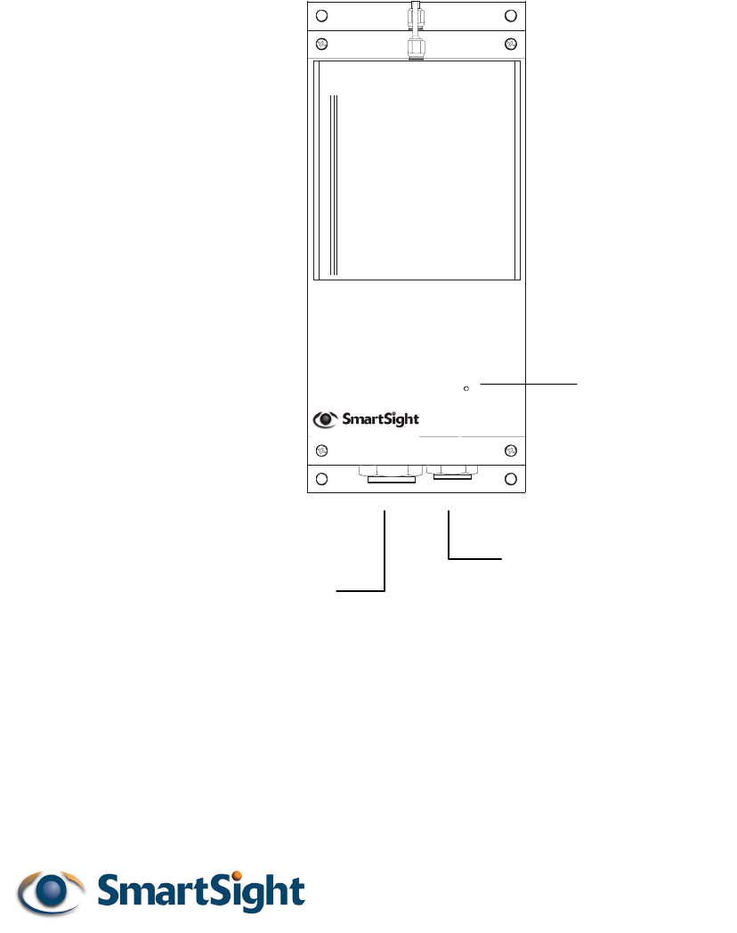
2.1 External module description
The S1000 (Transmitter) is labeled “Tx” and the S1000 (Receiver) is labeled “Rx”.
St at us
TM
Figure 1 S1000 – External view.
The S1000 electronics are enclosed in a weather-tight cast aluminum module. All
cable entries are mounted on the underside of the module to maintain its weather-
tight properties. The front panel of the S1000 integrates one bi-color visual indicator
that indicates the module operational state.
Main connector
(Video, Power
and Serial Port)
Auxiliary connector
(Alarm I/O and Audio)
Status indicator

3
SmartSightTM 1000 User Manual / Rev 0.33b
2.2 Applications
The current software version of the S1000 supports operation in point-to-point.
Future software upgrades will support transmission of video to multiple receivers as
well as retransmission of signal in none-line-of-sight application.
The S1000 supports 3 non-overlapping channels (channels 1, 6 and 11) or
operation of 3 simultaneous links within the same location. It is also possible to
support up to 6 links simultaneously with each of the six receivers installed at the
same location. However, this requires some site planning (see CHAPTER 4).
In most case, you will need to program a unique SSID (security ID) for each radio
system (see 4.2.4 to learn how to configure each module using a computer). As an
example, for 3 S1000 systems, 3 individual SSID are required. The table below
shows the configuration applied to each module:
Module Configured Channel Configured SSID
S1000-TX 1 1 SYSTEMA
S1000-RX 1 1 SYSTEMA
S1000-TX 2 6 SYSTEMB
S1000-RX 2 6 SYSTEMB
S1000-TX 3 11 SYSTEMC
S1000-RX 3 11 SYSTEMC
4
CHAPTER 3 S1000 System Configuration and Installation
3.1 S1000 system configuration
Your S1000 system is configured to operate right out of the box with the most
popular dome data port configurations (4800 baud, 8 data bits, no parity, 1 stop bit).
For added security, we recommend you change the SSID to your own secret SSID
and activate the WEP encryption and change the WEP key to your secret WEP key
before installing the system.
STEP 1 Initial Configuration
• Unpack the modules and set them side by side on a desk or table.
• Unpack the 2 cable assemblies (P/N S1000-CA-9P) and connect them to the
module (you must feel a positive click for the cable assembly connector to be
properly installed on the module)
• Connect the S1000-TX cable assembly DB-9 to a computer (if the DB9 has
been removed, refer to the table below to connect conductors properly) and
power the module (the STATUS LED should turn steady green and then
flashing green under normal operation; see the next section to understand
how this LED behaves under different operation conditions)
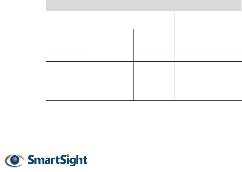
S1000-CA-9P TO PC CONNECTION
S1000 Cable Assembly Serial Port Description
(DCE port)
Computer
(DTE)
SIGNAL NAME WIRE PAIR WIRE COLOR SIGNAL NAME
CTS GREEN Not used
RxD
GREEN/
BLACK BLACK RX
TxD YELLOW TX
RTS
YELLOW/
BLACK BLACK Not used
Signal GND BROWN Signal GND
Signal GND
BROWN/
BLACK BLACK Signal GND
NOTE: Power the unit via the cable assembly RED & BLACK conductor
pair. The RED conductor is for 12 VDC input (or 24VAC if this
option was purchased) and the BLACK conductor is for the power
GROUND (or 24 VAC return if this option was selected).
5
SmartSightTM 1000 User Manual / Rev 0.33b
• Configure the S1000-TX SSID, WEP encryption key (if desired), radio
channel and serial port parameters (if required) via the computer (see 4.2.4
for configuration procedure)
• Connect the S1000-RX cable assembly DB-9 to the computer and power the
module (the STATUS LED should turn steady green under normal operation;
see the next section to understand how this LED behaves under different
operation conditions).
• Configure the S1000-RX parameters to the SAME parameters configured on
the S1000-TX
• You have completed the S1000 initial configuration. The system can now be
installed outdoors.
___________________________________________________________________
The S1000 integrates a single serial port. This port is used for both system configuration and data
communications (PTZ, access control or other). The serial port on the S1000 automatically detects
if it is connected to a computer (RS-232 serial port) or an RS-422 serial device. The user does not
have to configure the serial port for RS-232 or RS-422/485 operation or for configuration or data
communications.
__________________________________________________________________
3.2 Understanding the status led
The STATUS LED is a bi-color (GREEN-RED) LED which provides detailed
information on the system depending on whether the system is powering up, in
operation or the software is being updated.
Power-up sequence:
• Flashing Red (module is powering up)
• Steady Green (Application is started).
___________________________________________________________________
In very cold weather, the powering up sequence may take several minutes (up to 15 minutes at –
30°C). This is because the module must reach a certain internal temperature before powering up all
the electronics.
___________________________________________________________________
___________________________________________________________________
The following power-up conditions are abnormal:
1) LED not lit: Check the power supply and cabling, if power is available and the LED
stays off, call SmartSight technical support to obtain an RMA authorization.
2) Steady RED LED: There is an internal module error that prevents the unit from

6
starting normally. Power down and power back-up the module once. If the
condition persists proceed to a firmware upload (see CHAPTER 6) and if this fails
or the condition persists after the new upload, call SmartSight technical support
to obtain an RMA authorization.
____________________________________________________________________________
Tx After Power-up:
Flashing Green (steady rate) if not communicating with another module.
Flashing Green (various rate) if system communicating.
Flashing Green with intermittent Red flash if the radio link is not very good
and there are video frames lost.
Rx After Power-up:
Steady Green (if not communicating with another module).
Flashing Green (various rate) if system communicating.
Flashing Green with intermittent Red flash if the radio link is not very good
and there are video frames lost.
___________________________________________________________________
When communication is established between the transmitter and receiver, the GREEN LED flashing
rate is an indication of the number of frames transmitted every second. If the link is very good
the rate will be high. Under poor link conditions, the system will retransmit video frames constantly
and the frame rate will decrease as a result. If there are too many retransmission of video frames
some video frames may be lost and the picture quality may degrade momentarily (a flashing RED
LED indicates this state).
___________________________________________________________________
3.3 S1000 system installation
STEP 2 Installing the S1000 system in it’s final location
• Once your system is successfully configured it is ready to be installed
• Carefully review the site planning information presented in CHAPTER 4 to
optimize your system radio performance.
• If installing the S1000-TX on a light pole or mast, we suggest you use the
S1000-PM pole mount brackets and stainless steel clamps (for wall
mounting use the module side brackets).
• ALWAYS mount the S1000 modules with the industrial bayonet type black
connector pointing downwards.
• Connect the S1000-CA-9P cable assembly to the S1000 module and route
the cable to the dome or camera (all connections for the S1000-24VAC
model can be made inside a dome or motorized camera if 24 VAC is being
used for these devices). If the S1000-JB interconnection box is being used,
route all conductors to the S1000-JB first and then route all conductors from
the S1000-JB to the dome or camera).

7
SmartSightTM 1000 User Manual / Rev 0.33b
• Cut-off the DB-9 connector from the cable assembly in order to connect the
serial port to the dome or camera PTZ port terminals. Refer to one of the
following tables (whether using RS-422/485 or RS-232) to connect the serial
port to the target serial device:
S1000-CA-9P TO CUSTOMER EQUIPMENT CONNECTION
(RS-422/485 configuration)
S1000 Cable Assembly Serial Port Description
(DCE port)
Customer Equipment
(DTE)
SIGNAL NAME WIRE PAIR WIRE COLOR SIGNAL NAME
RxD+ GREEN RX+
RxD-
GREEN/
BLACK BLACK RX-
TxD+ YELLOW TX+
TxD-
YELLOW/
BLACK BLACK TX-
Signal GND BROWN Signal GND
Signal GND
BROWN/
BLACK BLACK Signal GND
S1000-CA-9P TO CUSTOMER EQUIPMENT CONNECTION
(RS-232 configuration)
S1000 Cable Assembly Serial Port Description
(DCE port)
Customer Equipment
(DTE)
SIGNAL NAME WIRE PAIR WIRE COLOR SIGNAL NAME
CTS GREEN CTS
RxD
GREEN/
BLACK BLACK RX
TxD YELLOW TX
RTS
YELLOW/
BLACK BLACK RTS
Signal GND BROWN Signal GND
Signal GND
BROWN/
BLACK BLACK Signal GND
• Carefully align the S1000-TX and RX modules so that both antennas are in
good line-of-sight alignment.
• Upon power up, verify that the STATUS LED turns STEADY or FLASHING
GREEN.
8
____________________________________________________________________________
The S1000 must always be installed with the black bayonet connector pointing
downwards. Failure to install the module properly can cause moisture to penetrate the
module and may void the warranty.
____________________________________________________________________________
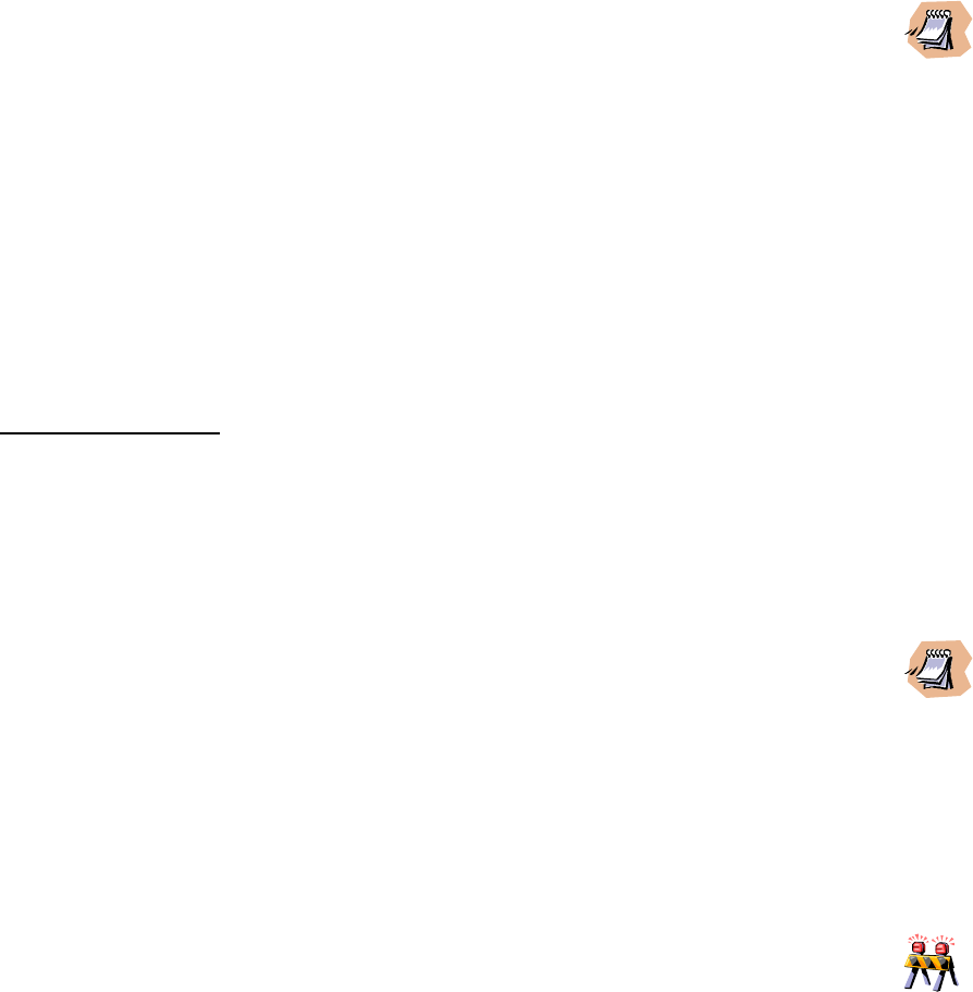
Figure 2 Example of a pole
mount installation
STEP 3 Installing the optional S1000-PA high gain antenna
• The S1000-PA is supplied with an adjustable pole mount bracket. It is
designed for mounting on a mast or pole of 2-3 inch diameter.
• The S1000-PA includes a one (1) meter pigtail cable to connect to the S1000
module. We recommend the antenna be mounted above the S1000 module.
Screw the pigtail connector (called an SMA connector) to the S1000 antenna
port and tighten with a small adjustable wrench (do not over-tight to avoid
damage to the connector)
• The antenna cable and connectors are weather-tight, however vibration
caused by the wind will over time loosen the connectors and reduce the
efficiency of the gaskets. The S1000-PA antenna is shipped with
waterproofing potty and electrical tape. We recommend you apply the potty
around the two junctions between connectors at both the antenna and
module end and wrap 2-3 layers of electrical tape around the potty.
• Carefully align the S1000-PA antenna with the other antenna so that both
antennas are in perfect line-of-sight.
9
SmartSightTM 1000 User Manual / Rev 0.33b
CHAPTER 4 Proper RF and Network Planning
The S1000 offers a robust and highly reliable spread spectrum wireless link, which can
operate up to 4 miles line-of-sight with appropriate installation.
For best operation, the system(s) must be properly planned (see section 4.1) and the
antennas must be installed in such a way as to obtain a line-of-sight link (see section 4.2)
4.1 Network Planning
4.1.1 Co-locating up to 3 systems
Three (3) S1000 can be co-located without special consideration for antenna
placement and antenna type. The following steps must be taken to operate three (3)
systems in the same area (failure to do so will cause interference between systems)
• Assign a unique SSID for each system (use any 4-32 characters for this ID). The
default SSID of each S1000 shipped is ‘SMARTSIGHT’.
• Assign channel 1 to one system, channel 6 to the second system and channel 11
to the last system.
4.1.2 Co-locating up to 6 systems (360 degree coverage)
If you are installing up to 6 S1000 receivers on the same mast and they are pointing
in different directions (at least covering 270 degrees), here is the procedure to use:
• Install the optional antenna S1000-PA on each S1000-RX (the integrated
antenna does not offer sufficient isolation to be used at the S1000-RX end in this
application).
• Assign a unique SSID for each system (use any 4-32 characters for this ID). The
default SSID of each S1000 shipped is ‘SMARTSIGHT’.
• Assign each system with a separate channel as shown in the table below:
10
Module Configured Channel Configured SSID
S1000-TX 1 1 SYSTEMA
S1000-RX 1 1 SYSTEMA
S1000-TX 2 3 SYSTEMB
S1000-RX 2 3 SYSTEMB
S1000-TX 3 5 SYSTEMC
S1000-RX 3 5 SYSTEMC
S1000-TX 4 7 SYSTEMD
S1000-RX 4 7 SYSTEMD
S1000-TX 5 9 SYSTEME
S1000-RX 5 9 SYSTEME
S1000-TX 6 11 SYSTEMF
S1000-RX 6 11 SYSTEMF
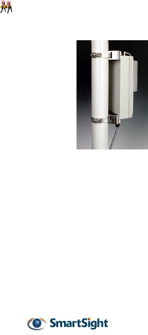
• Install the systems with the co-located channels (as an example channels 1 & 3,
channels 5 & 7 or channels 9 & 11) back to back or as close to back to back as
possible (as illustrated in Figure 3 below):
Figure 3 Cross-section view of S1000-RX antennas around
mast with proper channel allocation
System A
System B
System C
System D
System E
System F

11
SmartSightTM 1000 User Manual / Rev 0.33b
4.1.3 Co-locating up to 6 systems (less than 180 degree coverage)
If you are installing up to 6 S1000 receivers on the same side of a building or on the
same mast and they are pointing within the same direction (within 180 degrees
direction of each other), here is the procedure to use:
• Assign a unique SSID for each system (use any 4-32 characters for this ID). The
default SSID of each S1000 shipped is ‘SMARTSIGHT’.
• Assign two pairs of S1000-TX and RX modules on the same channel as shown in
the table below:
Module Configured Channel Configured SSID
S1000-TX 1 1 SYSTEMA
S1000-RX 1 1 SYSTEMA
S1000-TX 2 1 SYSTEMB
S1000-RX 2 1 SYSTEMB
S1000-TX 3 6 SYSTEMC
S1000-RX 3 6 SYSTEMC
S1000-TX 4 6 SYSTEMD
S1000-RX 4 6 SYSTEMD
S1000-TX 5 11 SYSTEME
S1000-RX 5 11 SYSTEME
S1000-TX 6 11 SYSTEMF
S1000-RX 6 11 SYSTEMF
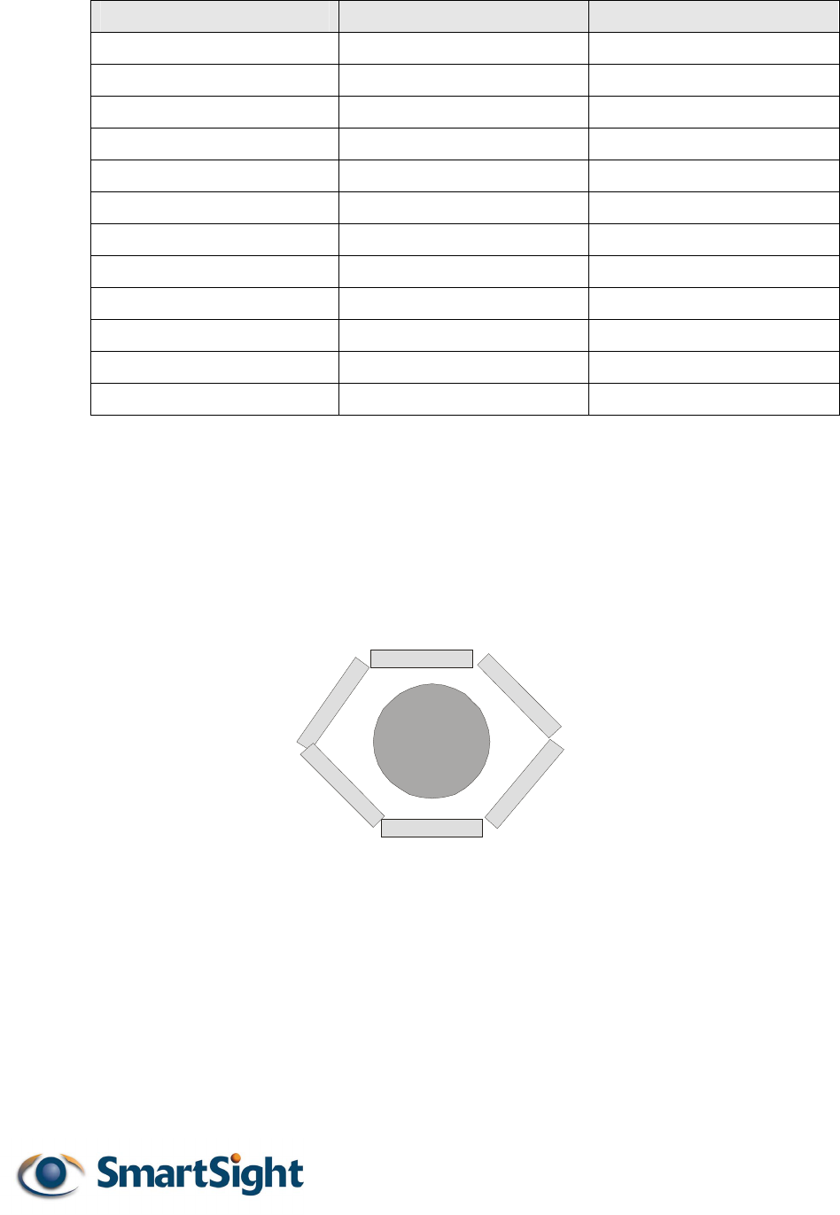
• Install the systems that share the same channels as close together as possible
(as illustrated in Figure 4 below). Each two systems will now share the radio
bandwidth available per channel.
12
Figure 4 Example of co-located systems with each 2 systems sharing one channel
4.1.4 Co-locating systems on different sides of a building
If you are installing S1000 systems on different sides of a large building or building
complex, you may be able to install more than 3 systems as long as two (2) S1000
systems that use a set of co-located frequencies (as an example channels 1 & 3) do
not offer a line-of-sight view to each other. Here is the procedure to use:
• Assign a unique SSID for each system (use any 4-32 characters for this ID). The
default SSID of each S1000 shipped is ‘SMARTSIGHT’.
• Assign each system with a separate channel as shown in the table presented in
section 4.1.2 above.
• Install the systems with the co-located channels (as an example channels 1 & 3,
channels 5 & 7 or channels 9 & 11) in areas that do not offer a line-of-sight view
to each other (for example on opposite side of the building).
Sy st e m A
Sy st e m B
Sy st e m C
Sy st e m D
Sy st e m E
Sy st e m F
Channel 1
Channel 1
Channel 6
Channel 6
Channel 11
Channel 11

13
SmartSightTM 1000 User Manual / Rev 0.33b
4.2 RF Planning
Successful operation of a S1000 network lies on the proper installation of the
wireless antennas. Such installation requires:
1. Evaluation of the location
2. Evaluation of antenna requirements
This section presents a step-by-step approach to completing the phases outlined
above.
4.2.1 Evaluation of the location
Unless it is a very short link distance (less 500 feet) the path between the two
antennas must be free of obstacles that could disturb propagation. Such path is
called a line-of-sight path. If there are obstacles, radio waves will be in part
absorbed and in part diffracted by the obstacles (multi-path fading). Even if
operating in such circumstances, links could be established. However, results
are highly unpredictable.
The first requirement of a successful link is therefore a clear line-of-sight path.
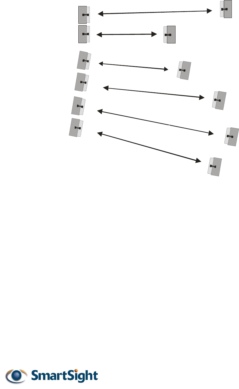
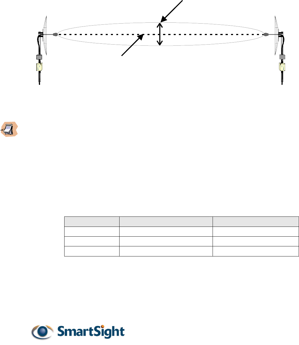
There is a second requirement related to the beam-width of a radio signal. The
beam-width of a radio signal transmitted between two antennas is an elliptical
area immediately surrounding the visual path (see Figure 5). It varies in
thickness depending on the length of the signal path. The region outlined by this
beam-width is known as the first Fresnel zone. The Fresnel zone is always
thicker at the mid-point between the two antennas. Therefore a path that
appears to be a perfect line-of-sight path between the base and a remote station
may not be adequate for a radio signal.
In practice, it has been determined that a radio path can be considered a line-of-
sight path if it has a clear opening through 60% of the first Fresnel zone (0.6 F1).
The table below presents the value of 0.6 F1 for various signal path distances. A
common problem encountered in the field and related to the 0.6F1 clearance rule
is a building obstruction. The proposed visual path may just barely clear a
building but the “radio line-of-sight” won’t. In such case, the signal will be partially
absorbed and diffracted. Increasing the height of the two antennas or the gain of
the antennas, are the only alternatives to improve the link quality.
DISTANCE
(mile)
0.6F1@ 2.45 GHz
(feet)
1 15
4 25
7 40
15 75
14
Table 1 – 0.6F1 Values (including effect
of earth curvature) at Various Distances
VISUAL LINE OF SIGHT
FIRST FRESNEL
ZONE (F1)
Figure 5 Difference Between Fresnel Zone and Visual Line-of-Sight.
___________________________________________________________________
At 2.4 GHz, radio waves are highly attenuated by dense foliage. A link established in the
fall or winter season may be adversely affected in the spring and summertime, if it is
established below tree level.
___________________________________________________________________
4.2.2 Evaluation of antenna requirements
SmartSight offers two type of antennas to meet various distance requirements of
clients, the integrated 8.5 dBi patch antenna or an external 16 dBi gain patch
antenna (option S1000-PA). These can be combined together to offer the
following combinations and associated system range:
Range S1000-TX Antenna Gain S1000-RX Antenna Gain
4 miles 8.5 dBi 8.5 dBi
7 miles 8.5 dBi 16 dBi
15 miles 16 dBi 16 dBi
Note: The above ranges are specific to a S1000 system configured at 1Mbps.
The range is reduced by 30% at 2 Mbps data rate.
4.2.3 Coping with Interference
In most countries, the 2.4 GHz license free band is not regulated by a government
agency and this absence of frequency coordination can result in interference
15
SmartSightTM 1000 User Manual / Rev 0.33b
between various systems. Fortunately, there are existing tools that can be used to
avert interference:
(1) RF channel selection
(2) Antenna selection
(1) RF channel selection
The S1000 offers eleven (11) channels to choose from. If a link with a good line-
of-sight is subject to excessive video delay and very low frame rate (or possibly
break down of video images), it could be due to interference. In this case it is
recommended to change channel until a clean channel is found.
(2) Antenna Selection
Replacement of the integrated antenna by the S1000-PA 16 dBi gain antenna
can significantly lower interference from other radio systems. If a link with a good
line-of-sight is subject to excessive video delay and very low frame rate (or
possibly break down of video images), it could be due to interference. If
switching channels does not correct the problem or if all channels must be used
to co-locate several systems, it is recommended to replace the integrated
antenna with the S1000-PA to resolve the interference problem.
4.2.4 RF Exposure Considerations
In order to comply with the RF exposure requirements of CFR47 1.1310, the S1000 must be
installed in such a way as to allow a minimum separation distance of 20 cm (4 in.) between
antennas and persons nearby.

16
CHAPTER 5 Using the Command Line Interface to program
the S1000
This chapter guides you through a step by step procedure to program your S1000
modules. Programming the S1000 does not require the installation of any software on
your computer. All you will need is a terminal emulation program such as Hyper Terminal
supplied with all Windows or Macintosh operating systems. Your computer must also
integrate a serial COM port for connection to the S1000 module.
5.1 Reset to factory default
(NOTE: Reset functionality will not be available until release 1.0 of the firmware).
If at any time during the system configuration the system becomes unstable or stops
responding (possibly due to the entering of a wrong value via the CLI) it is possible
to perform a hardware reset. This hardware reset will cause a reset to factory
configured parameters.
The hardware reset is invoked by shorting together the serial port's CTS and TxD
pins during the power-up sequence (The S1000-CA-9P cable assembly pin-out is
presented in APPENDIX 2, figure 2). To do this proceed as follows:
1. Power down the unit
2. Short TxD & CTS conductors together
3. Power up the module and wait until the normal boot up sequence is
completed
4. Remove the short on the TxD & CTS pins
5. The module is ready for use with Factory Configuration settings (see
Appendix 1 for a list of these settings)
Following a configuration reset, the S1000-TX or RX module might need to be re-
programmed for proper operation with the other module.
5.2 Hyper Terminal
Hyper Terminal is the terminal program within WindowsTM that is used to configure
the modules. You may use any other ASCII based terminal emulation
communication programs. The graphical interface presented in the following
examples is based on WindowsTM Hyper Terminal Version 1.2. Using a different
version of WindowsTM Hyper Terminal may offer a different graphical interface.
17
SmartSightTM 1000 User Manual / Rev 0.33b
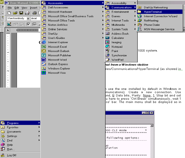
5.2.1 Starting the Hyper Terminal from Windows 98
Connect the S1000 module to the COM1 port (or COM2 or COM3 if there are more
than one COM port on your computer) of the computer using the S1000-CA-9P DB9
serial connector. Next, power the S1000 and start Hyper Terminal by selecting the
following in the WindowsTM START menu:
Start/Programs/Accessories/Communications/HyperTerminal (as shown in ‘Figure
6‘).
Figure 6 Starting Hyper Terminal from Windows 98
- Double click on HYPER TERMINAL to start.
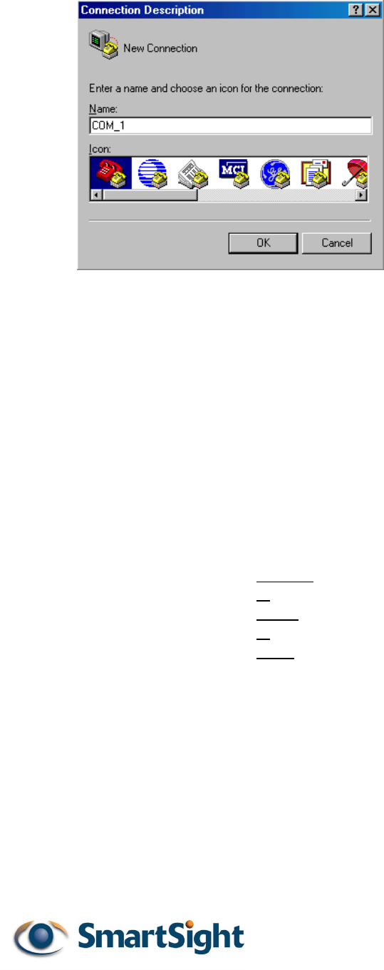
- You should see a window as the one in ‘
-
- Figure 7’.
- Enter ‘COM_1’ (or any other name such as S1000) in the name field.
- Click OK.
- Click CANCEL.
18
Figure 7 Hyper Terminal
startup screen
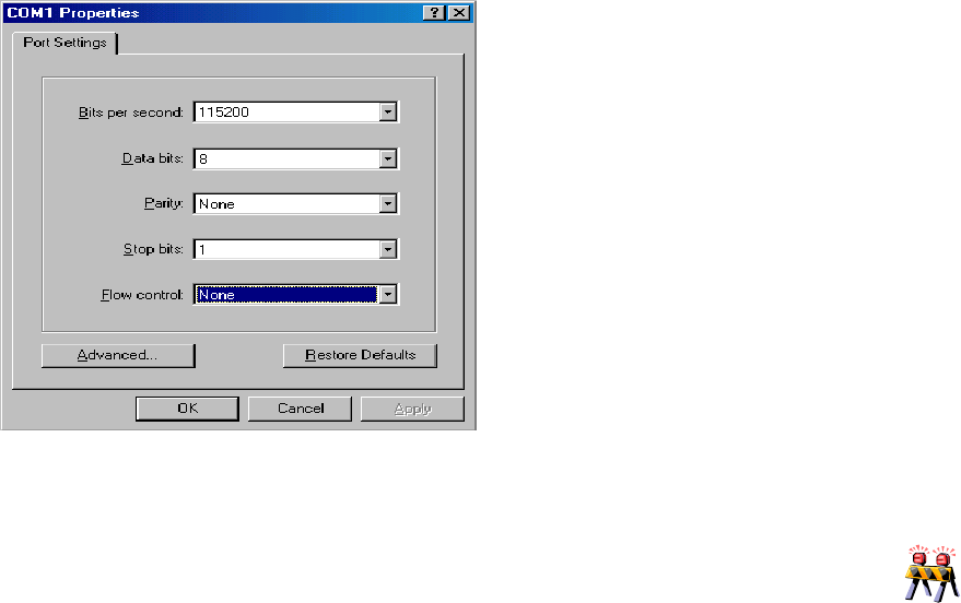
5.2.2 Configuring Hyper Terminal
Before using Hyper Terminal you will have to set the computer serial port
parameters.
- Click on FILE/PROPERTIES.
- In ”CONNECT USING” box: select COM1 (unless you are using a different COM
port)
- Click on CONFIGURE.
You should now see the same window as in (‘Figure 8’).
Set:
• Bits per second: 115200.
• Data bits: 8.
• Parity: None.
• Stop bit: 1.
• Flow Control: None.
- Click OK.
- Click OK again
19
SmartSightTM 1000 User Manual / Rev 0.33b
Figure 8 Hyper Terminal
configuration
window
____________________________________________________________________________
If you have installed a PDA synchronization program on your computer such as Palm
HOTSYNCTM and it is using the COM port (not a USB or Infrared port) , you will first need
to disable this program if it is active. Failure to do so will prevent you from successfully
using the COM port to configure the S1000 system.
____________________________________________________________________________
5.3 S1000 CLI
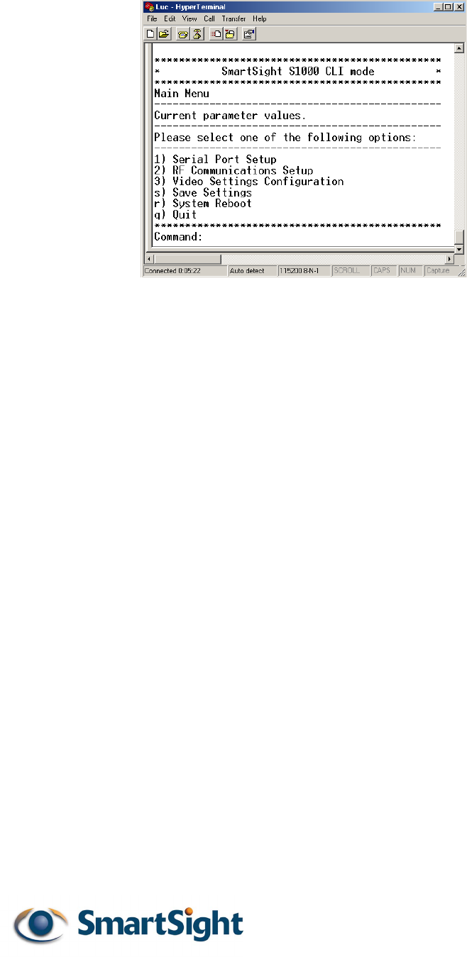
5.3.1 Starting the CLI
Now that Hyper Terminal is started, you have to start the SmartSight 1000 CLI.
On the keyboard
- Press ‘Ctrl-Break’ simultaneously, wait 1 second and then press the ‘Space’ bar.
The SmartSight 1000 CLI menu should appear as seen in ’Figure 9’
20
Figure 9 CLI start up
screen
5.3.2 Using the CLI
In the CLI menu, enter <1>, <2> or <3> at the command line to enter the Serial Port,
RF Communications or Video Settings. All entries must be followed by <ENTER> to
take effect. You can always return to the previous menu by entering <r>. All letters
entered in the CLI must be lower case.
Once all the changes have been made enter <s> at the command line to save all the
changes you have made. You will need to power down and re-power up to enable
the changes.
Sections 5.4, 5.5 and 5.6 provide a list of all parameters that can be modified by the
user and an explanation of these parameters.
5.4 Serial port setup
5.4.1 Bit rate
The bit rate represents the data rate the target product (dome, keyboard, matrix,
multiplexer or access card) operates at. Refer to the product manual or contact your
product manufacturer if you are unsure of the data rate of the specific product you
wish to interface with.
5.4.2 Parity
The parity is either odd or even or there is no parity check. Most communications
devices do not use parity. Refer to the product manual or contact your product
manufacturer if you are unsure if parity is used in the specific product you wish to
interface with.

21
SmartSightTM 1000 User Manual / Rev 0.33b
5.5 RF communications setup
5.5.1 RF channel
This option is used to configure the channel (frequency) that will be used by the
SmartSight™ 1000 Units (Tx / Rx). A set of 11 channels are available.
Co-located systems should always be set on different channels unless two systems
are set-up to share a channel (refer to CHAPTER 4 for a more in-depth
explanation). It might be also necessary to change channel if interference is present
on one specific channel.
5.5.2 SSID
This option identifies a pair of Units (TX and RX) that belong to the same S1000
system. The SSID must be the same for both the TX and RX module. Co-located
systems must always be set on different SSID.
The SSID is represented by an ASCII string of 1 to 32 characters (numbers or
letters). Here are examples of valid SSID:
SMARTSIGHT1000
RadioCommunications2001
123456789
wirelessvideo
welcome
5.5.3 Bit rate
Bit rates can be set to 1 Mbps, 2 Mbps, 5.5 Mbps or 11 Mbps where Mbps stands
for Mega bits per second. A high bit rate reduces the effective distance between two
functional Units. We recommend you use 2 Mbps for all system installations unless
the link is not reliable. If this is the case, use 1 Mbps to improve the link quality.
Using 1 Mbps will however slightly reduce the video frame rate. 5.5 and 11 Mbps
should never be used at this time, they are reserved for future applications.
5.5.4 WEP Key
WEP (Wire Equivalent Privacy) encryption is a mechanism that provides protection
from eavesdropping using another S1000 system or a computer equipped with a
wireless 802.11b receiver.
The WEP key is used by the system to generate a unique encryption sequence.
The WEP key must be the same for the TX and RX for the system to communicate
together.
The WEP key is represented by an ASCII string of 5 characters. Note that the WEP
key is write only. This feature is to ensure privacy of the WEP key.
Here are examples of valid WEP key:

22
12345
VIDEO
SECUr
$$$$$
_WEP*
5.5.5 WEP Encryption activation
This option enables or disables encryption. If the WEP encryption is disabled, the
system will still offer some level of protection through the unique SSID entered.
SSID is not a technique of encryption, a hacker with a computer and a wireless
802.11b compliant card could receive and decode the video being received if
encryption is not enabled. Note however that someone purchasing a S1000 will not
be able to receive video from another S1000 system if the SSID is not known.
5.6 Video Settings setup
5.6.1 Target frame rate
The ‘target frame rate’ is the maximum number of frame per seconds (fps) that will
be compressed and transferred between the TX and RX modules. This parameter
can be set to 15 fps and 30 fps through the CLI.
Some level of ‘pixalization’ will occur when setting the module for 30 fps. This is
because quality will be sacrificed for frame rate. At 15 fps, the video quality will be
maintained even when panning or tilting.
5.6.2 Set target bit rate
The target bit rate is defined as the maximum number of bits per second generated
by the video transmitter (S1000-TX). Valid bit rates are between 64Kbps and
1000Kbps.
We recommend setting this parameter to 800Kbps for maximum video quality.
5.6.3 Video standard: PAL / NTSC
The S1000 Receivers and Transmitters support two analog video Standards: NTSC
and PAL. NTSC is the analog television display standard that is used in North
America and certain other parts of the world. PAL is the analog television display
standard that is used in Europe and certain other parts of the world.
23
SmartSightTM 1000 User Manual / Rev 0.33b
CHAPTER 6 Upgrading the S1000 firmware
This chapter provides information on using the SmartSightTM Management Interface (SMI)
to upgrade your S1000 firmware. The SMI is a user friendly and easy-to-use graphical
interface running on all Windows TM compatible PCs.
Install the SMI program supplied with the S1000 system on your computer and then follow
the steps below to use the SMI program. Firmware upgrades or patches can be found in
the support section of the SmartSightTM website.
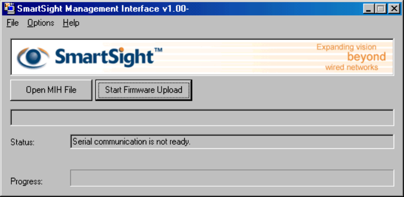
6.1 Starting the SmartSightTM Management Interface
Via Windows ExplorerTM (or any other file browser), select the <SMI.EXE> file and
then press enter or double-click with the mouse. A window will appear as seen in
‘Figure 10’. SMI.EXE can also be launched from MS-DOS prompt.
Figure 10 SMI start up screen
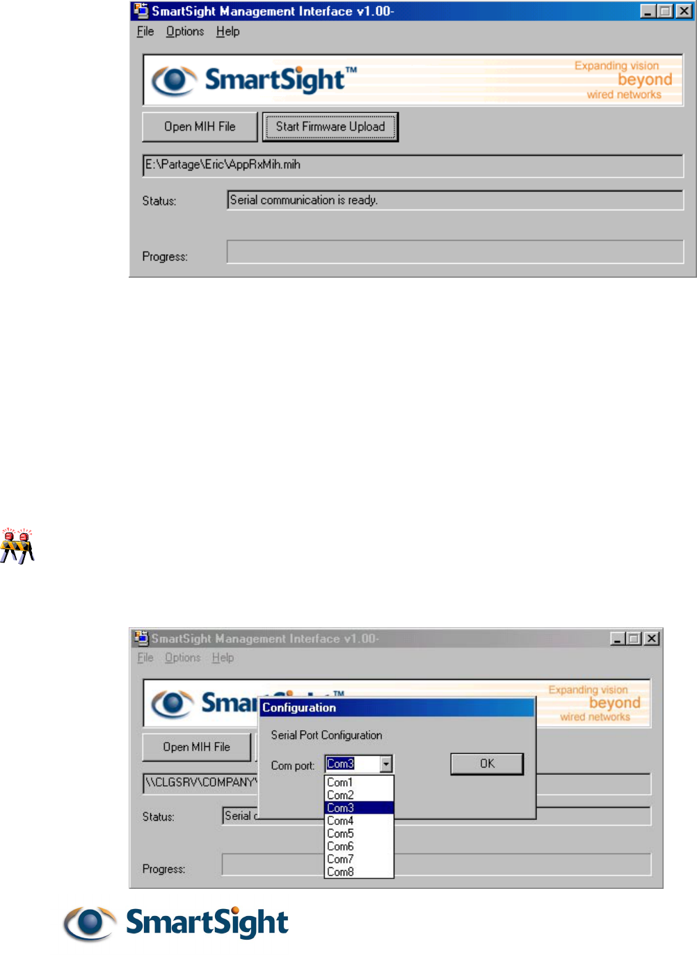
6.2 Performing a Firmware Upload
Steps described below should be followed carefully while doing a Firmware Upload.
STEP 1. Connect the S1000-TX computer via the serial port. If the DB9 connector
was removed from the S1000-CA-9P cable assembly, you will need to re-
install this connector to connect with the PC (refer to APPENDIX 2 for the
cable pin-out).
24
Figure 11 Screen shot before a firmware upload
STEP 2. If you are not using your computer’s COM1 serial port (the default port
used by the SMI program after installation), you will have to select the
correct serial port number on your computer by choosing the <Options>,
<Serial port setup> path from the SMI menu. A window as the one
showed in ‘Figure 12’ will appear.
Note: Once you have launched SMI once, the next time you start the
program it will use the last COM port selected and point to the last file
uploaded.
____________________________________________________________________________
If you have installed a PDA synchronization program on your computer such as Palm
HOTSYNCTM and it is using the COM port (not a USB or Infrared port) , you will first need
to disable this program if it is active. Failure to do so will prevent the SMI program from
opening the COM port..
____________________________________________________________________________

25
SmartSightTM 1000 User Manual / Rev 0.33b
Figure 12 Serial Port Configuration Window
STEP 3. Open a valid S1000 firmware file (called an “MIH” file) by pressing the
<Open MIH File> button and selecting the appropriate file. A valid MIH
file can be obtained via SmartSight™ technical support at
techsupport@smartsightnetworks.com.
STEP 4. Start firmware upload by pressing the <Start Firmware Upload> button.
The upload task will take a few minutes to complete.
The status box may display several status messages while using the SMI. Here is a
list of these messages:
1. “Serial communication is ready”. SMI has opened the communication port. The
connection is ready to be used.
2. “Serial communication is not ready”. SMI cannot open the communication port (check
to see if you are using the correct COM port or if the COM port is being used by another
application).
3. “Failed to send break sequence”. This message should never appear. If it does,
please contact SmartSight technical support.
4. “Starting firmware upload”. Indicates that the upload process has begun.
5. “Write operation timed-out” or “Could not write to serial port”. These messages
should never appear. Please quit all programs, restart Windows and make sure that SMI
is the only program running. If the problem persists, please contact SmartSight technical
support.
6. “Firmware upgrade request sent”. SMI has made a request to the S1000 for upgrade.
7. “Reception timed-out. Please verify that serial cable is properly connected”. Verify
the quality of the cable assembly. If the problem persists, please contact SmartSight
technical support.
8. “Communication established”. The SMI program is now communicating with the
device.
9. “Reception timed-out. Retry attempt #1”. The connection established has been
broken. It may be caused by a disconnected cable.
10. “Communication aborted. Max retries reached”. If the problem reported at 9 is not
resolved after the 10th attempt (this will take a few minutes), the communication is
aborted. Please verify that the cable is not damaged and is installed properly. If the
problem persists, please contact SmartSight technical support.
11. “Firmware upload in progress”. The upload process is in progress.
12. “Firmware upload done”. The upload process has been completed successfully.
13. “Invalid firmware file”. Select a valid file. If the problem persists contact SmartSight
Technical Support to obtain a valid file.

26
APPENDIX 1 Factory Default Configuration
If the S1000 fails to respond after programming it with the CLI or SMI, it can be reset to a
factory default configuration by activating the reset switch. (See 4.2.4 for reset to factory
default procedure)
The S1000 is programmed at the factory with the following configuration (underlined
parameters cannot be modified by the user):
• Serial port setup
• Bit rate: 4800 bauds
• Parity: NONE
• Number of stop bits: 1
• Duplex mode: FULL
• Line driver: RS485 (Auto-detected)
• Number of data bits: 8
• Handshake: Off
• RF communications setup
• RF channel: 1
• SSID: “SMARTSIGHT”
• WEP Encryption activation: Off
• WEP key: WILLIE
• Bit rate: 2Mbps
• Video settings configuration
• Target frame rate: 15
• Target bit rate: 800 Kbps
• Video standard: NTSC
27
SmartSightTM 1000 User Manual / Rev 0.33b
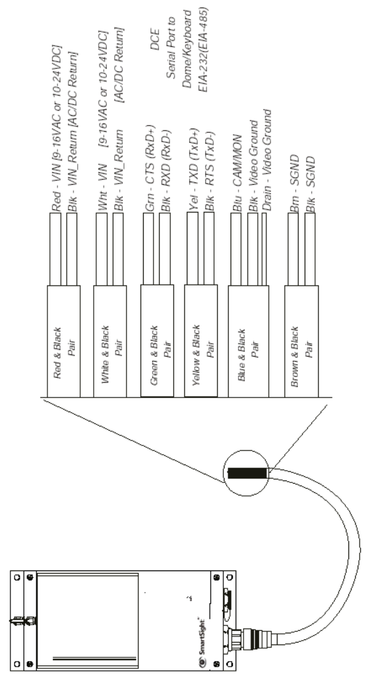
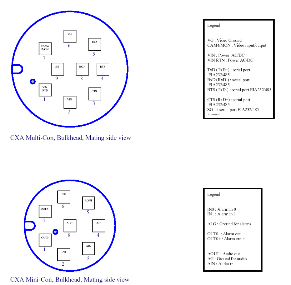
APPENDIX 2 PIN description for S1000 connectors & S1000-CA-9P
Figure 1 below presents the pin-out configuration for the 9 pins bayonet type connector on the
S1000 module and Figure 2 presents the pin-out configuration for the S1000-CA-9P cable
assembly.