SmartStuff SSI-CTRLR VirtualZone CONTROLLER SSC User Manual
SmartStuff, Inc. VirtualZone CONTROLLER SSC Users Manual
Users Manual

VirtualZone®
USER MANUAL
SmartStuff Inc.
7001 Sassfrass Court
Summerville, SC 29485
Tel. 860-202-1845
Fax. zzz-xxx-yyyy
www.smartstff.com

Table of Contents
1 INTRODUCTION ...................................................................................................... 3
2 EQUIPMENT SAFETY COMPLIANCE .................................................................... 9
3 GENERAL SAFETY GUIDELINES ........................................................................ 11
4 UNPACKING AND PARTS LIST ............................................................................ 13
5 INTELLIGENT ZONE CONTROLLER INSTALLATION ......................................... 14
6 SmartDamper Installation ....................................................................................... 19
7 SmartSensor ......................................................................................................... 23
8 VirtualZone Smart Application ............................................................................... 24
Appendix A PIPE WALL MEASUREMENT SYSTEM SPECIFICATIONS ............... 27

24000-01 Rev 01
Page 3
1 INTRODUCTION
1.1 Introduction
VirtualZone® is an intelligent zone temperature control system consisting of an
array of by SmartSensorTM devices and SmartDamperTM devices coordinated by
an Intelligent Zone Controller (SmartController™). VirtualZone® converts a
traditional heating/cooling zone into up to four separate intelligent “sub zones” to
provide unprecedented room-by-room climate control, enery efficiency, and
occupant comfort. VirtualZone® allows the temperature in each room to be
individually and automatically controlled, ensuring every room is the right
temperature at the right time. Temperatures can even be monitored and controlled
from the convenience of your smartphone.
VirtualZone® leverages Bluetooth® SMART technology, for efficient Low Energy
wireless communication between components.
The VirtualZone® system consists of an Intelligent Zone Controller, which
connects to the HVAC system, SmartSensorTM devices, which monitor
temperature in each separate “sub-zone”, and SmartDamperTM vents, which
control air flow to individual heat/cool vents.
This manual covers the basic installation and setup of the VirtualZone® system. In
all cases, local safety and operating practices take precedence over the
information contained within this document.
24000-01 Rev 01
Page 4
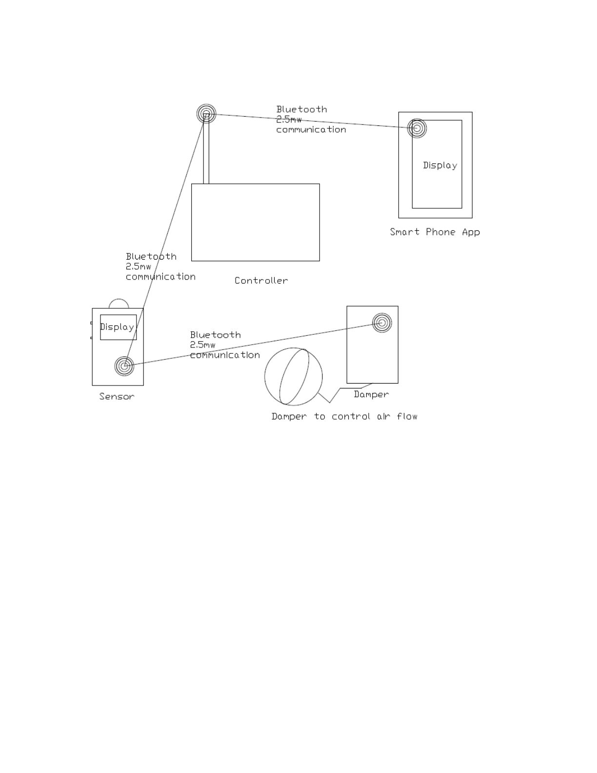
1.2 SmartController™ Description and Function
The SmartController™ device controls to the HVAC system, coordinates
Bluetooth® communications between the SmartSensor™ devices and the
VirtualZone® application running on the smartphone. The SmartController™
device contains the operational database which stores all of the configuration
settings and commands the HVAC system to deliver heating or cooling.
Illustration 1: System Block Diagram
24000-01 Rev 01
Page 5
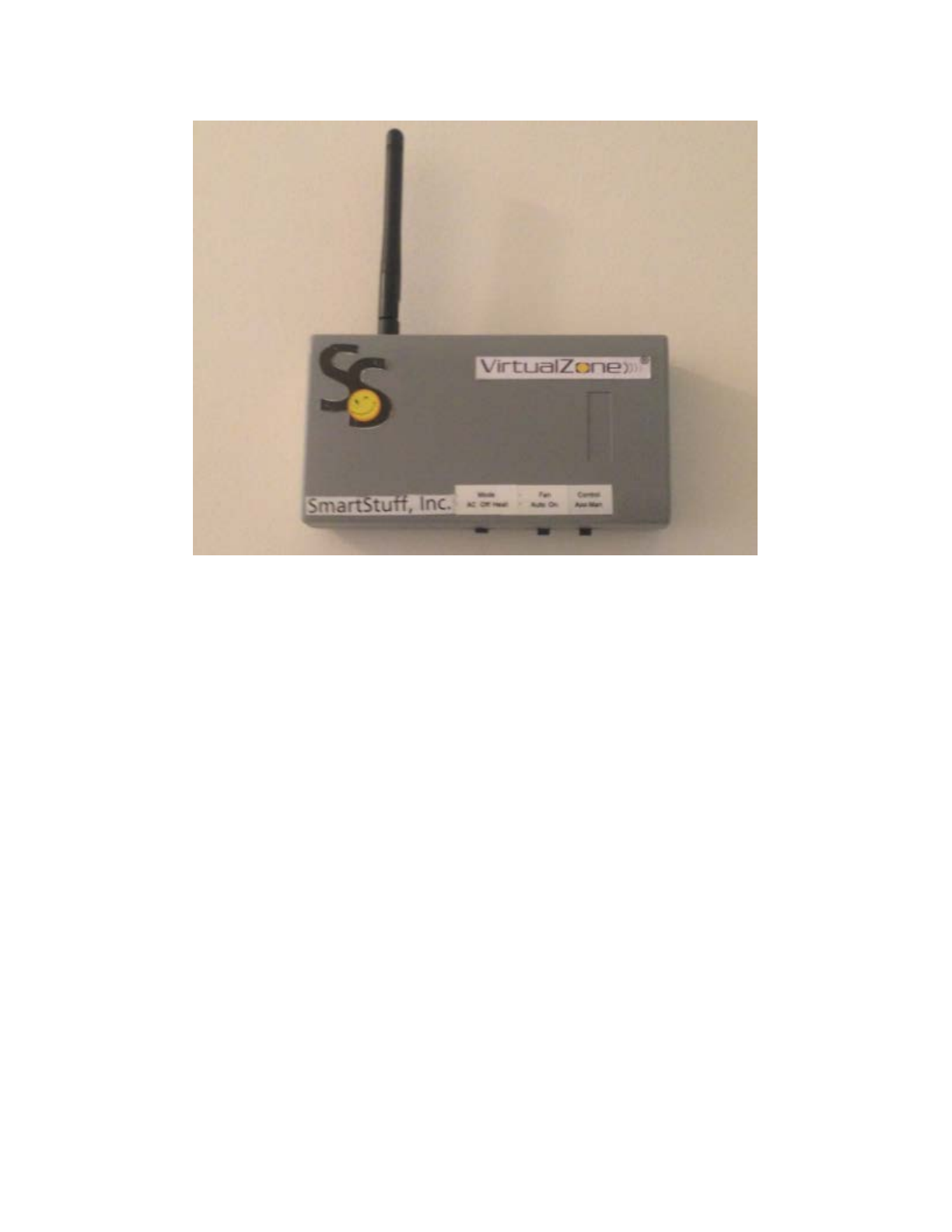
The SmartController™ device is periodically polled, or communicated with, by
each of the SmartSensor™ devices inquiring about configuration changes. The
VirtualZone® smart phone application has the ability to establish a Bluetooth®
connection to the SmartController™ and read its entire database. This information
is now presented to the user for modification via the app. Upon user requesting
that changes made via the app should be saved, another Bluetooth® connection
between the SmartController™ and the smart phone is established and the entire
modified database is written back to the SmartController™. The next time a
SmartSensor™ device establishes a Bluetooth® connection with the
SmartController™ it will be notified if any pertinent changes have occurred.
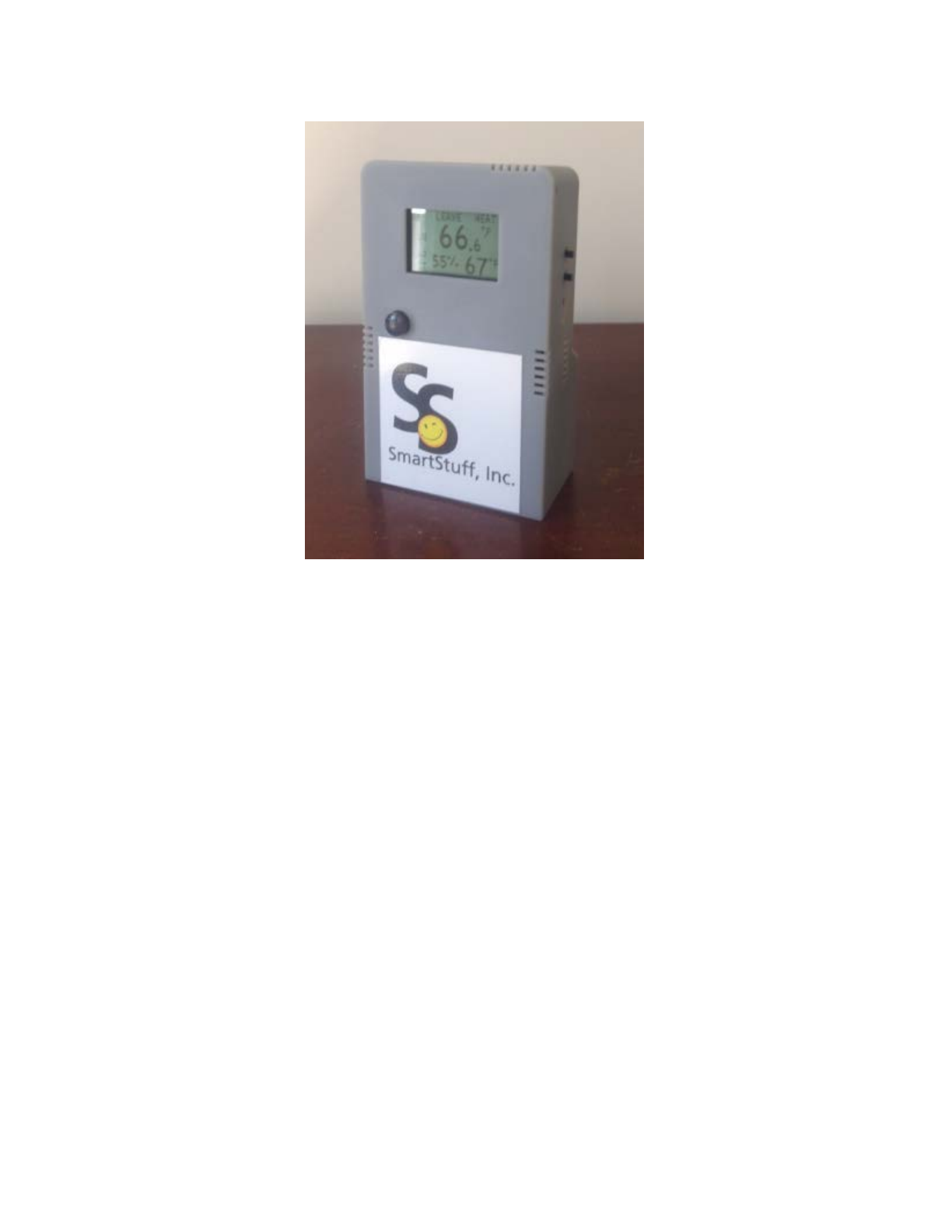
1.3 SmartSensor™ Description and Function
The SmartSensor™ device measures and displays the current temperature as well
as system configuration settings. It is a portable device which can be placed
anywhere in the “sub-zone” to achieve sub-zone temperature management and
control. On a periodic basis it communicates with the SmartController™ via a
Bluetooth® connection. When temperature in the “sub-zone” goes above or below
the desired temperature the SmartSensor™ commands the SmartController™ to
activate/deactivate the cooling/heating system for the HVAC zone.
Illustration 2: SmartController™
24000-01 Rev 01
Page 6
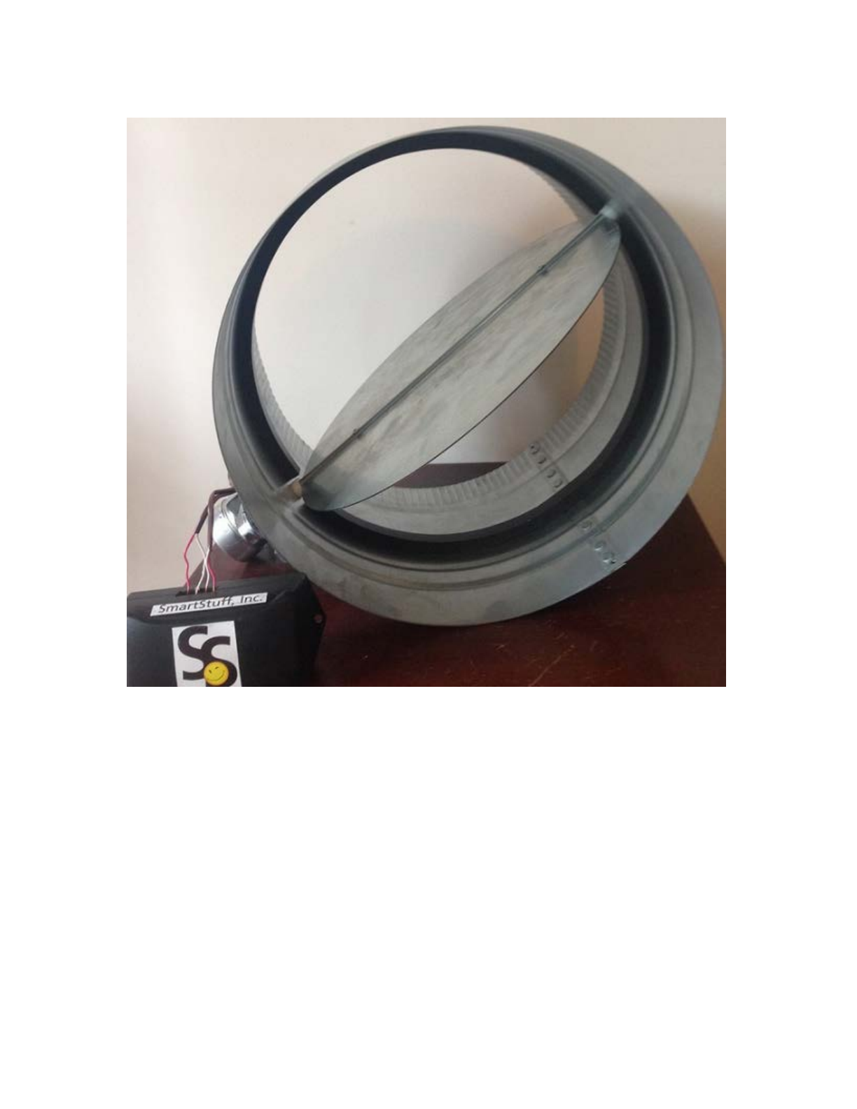
1.4 SmartDamper™ Description and Function
The SmartDamper™ is a duct insert and plastic enclosure that controls operation
of the damper. It is placed in-line in the duct work and controls the airflow into its
designated sub-zone. The SmartDamper™ can, on command, restrict or allow
airflow to the “sub-zone”. On a needed basis it communicated with by the
SmartSensor™ over Bluetooth®. When the SmartSensor™ device determines
that airflow is needed into the sub-zone, it commands the SmartDamper™ to open
which allows airflow into the “sub-zone”. Conversely, when the SmartSensor™
device determines that airflow is no longer necessary in the sub-zone, it
commands the SmartDamper™ to close thus preventing airflow into the “sub-
zone”.
Illustration 3: SmartSensor™
24000-01 Rev 01
Page 7
Illustration 4: SmartDamper™ System
24000-01 Rev 01
Page 8
1.5 Intellectual Property Notices
VirtualZone® devices are covered by the following granted U.S. Patent(s):
xxxxxxxxxx; Other are pending; see www.smartstff.com for the latest listing of
patents.
This manual is covered by U.S. and international copyright laws. No part of this
manual may be reproduced, modified or transmitted in whole or in part in any form
or by any means, electronic or mechanical, including photocopy, recording, or any
information storage and retrieval system, without permission in writing from
SmartStuff Inc.
Copyright © 2014 by SmartStuff, all rights reserved.
SmartSensorTM , SmartDamperTM, VirtualZone® and logo are trademarks of
SmartStuff Inc.
1.6 Warranty
The terms and conditions, including warranty, of the purchase of VirtualZone
System are outlined in the document entitled “SmartStuff Terms and Conditions of
Sale”.
1.7 Contact Information
SmartStuff Inc.
7001 Sassfrass Court
Summerville, SC, USA
Telephone: 1-860-202-1845
Website: www.smartstff.com
Sales Support: sales@smartstff.com
Customer and Technical Support: customersupport@smartstff.com
Illustration 5: SmartDampe™r Control
24000-01 Rev 01
Page 9
2 EQUIPMENT SAFETY COMPLIANCE
2.1 North American Emissions
This equipment is compliant with Class B limits for radiated and conducted radio
noise emissions, as defined in Subpart B of Part 15 of the FCC rules.
FCC Radiation Exposure Statement
This equipment complies with FCC RF radiation exposure limits set forth for an
uncontrolled environment. This transmitter must not be co-located or operating in
conjunction with any other antenna or transmitter.
This device complies with Part 15 of the FCC Rules, operation is subject to
the following two conditions: (1) This device may not cause harmful
interference, and (2) this device must accept any interference received,
including interference that
may cause undesired operation
• Warning: Changes or modifications to this unit not expressly approved by
the party responsible for compliance could void the user’s authority to
operate the equipment.
• NOTE: This equipment has been tested and found to comply with the
limits for a Class B digital device, pursuant to Part 15 of the FCC Rules.
These limits are designed to provide reasonable protection against harmful
interference in a residential installation. This equipment generates, uses and can
radiate radio frequency energy and, if not installed and used in accordance with
the instructions, may cause harmful interference to radio communications.
However, there is no guarantee that interference will not occur in a particular
installation. If this equipment does cause harmful interference to radio or
television reception, which can be determined by turning the equipment off and
on, the user is encouraged to try to correct the interference by one or more of the
following measures:
• Reorient or relocate the SmartSensorTM.
• Increase the separation between the equipment and SmartSensorTM.
24000-01 Rev 01
Page 10
3 GENERAL SAFETY GUIDELINES
3.1 Introduction
This manual is intended to be a general installation guide for the VirtualZone®
Zone Temperature Control System. It is not intended to cover the installation
details for every application due to the wide variety of installations on which the
system can be used. In all cases, local safety and operating practices should take
precedence over instructions contained within this manual.
The installer must fully read this manual prior to installing and operating the
VirtualZone® Climate Control System.
3.2 Safety Precautions
The following style of Warnings and Cautions are used throughout the manual to
draw attention to information regarding personnel safety and equipment care.
They are intended to supplement but not replace local or plant safety procedures.
WARNING
Situation has the potential to cause bodily injury.
CAUTION
Situation has the potential to cause damage to property or
equipment.
3.3 Definitions of Symbols
The following terms and symbols are used in this document and on the passive
sonar meter where safety related issues occur.
3.3.1 General Warning or Caution
Figure 1 General Warning or Caution Symbol
The Exclamation Symbol in Figure 1 appears in Warning and Caution
tables throughout this document. This symbol designates an area where
personal injury or damage to the equipment is possible.

24000-01 Rev 01
Page 11
3.3.2 General Warnings and Cautions
Observe these rules when operating or servicing this equipment:
• Prior to operation of this equipment, read the instruction manual
thoroughly.
• Follow all warnings on the unit and in the operating instructions.
• This product should only be powered as described in the manual.
Read the instructions for proper input voltage range selection.
• Ensure all power cords, and interface cables are properly routed to
eliminate damage to them. Cable conduit may be desirable to
minimize potential damage.
• Use only manufacturer specified replacement parts.
• Follow static sensitive device precautions when installing.
24000-01 Rev 01
Page 12
4 UNPACKING AND PARTS LIST
4.1 Unpacking
The Virtual Zone Climate Control System will typically be packaged in one
shipping container. One box will contain all components, and installation
hardware.
Note: The original packing materials should be saved whenever possible in the
event that the system is removed or relocated.
CAUTION
Use care in unpacking and transporting system. Improper
handling may result in damage to system components.
4.2 Inventory of Parts
Table 1 lists the parts contained in the shipping containers.
Description
VirtualZone® Zone Temperature Control System
SmartController™
SmartSensor™
SmartDamper™
Installation Hardware
System Installation & Startup Manual
Table 1 VirtualZone® Parts List

24000-01 Rev 01
Page 13
5 SmartController™ INSTALLATION
5.1 Introduction
The SmartController™ connects to the HVAC system. The installation assumes a
pre-existing thermostat.
The following sections detail the installation of the SmartController™.
5.1.1 SmartController™ Power Requirements
The Wall Thickness Monitor band is powered from the HVAC system. The
HVAC provides 24VAC + 10%.
5.1.2 Installation Tools
The installation of the SmartController™ requires the following tools.
• Phillips screwdriver
• Drill with 3/16 bit for wall mounts
24000-01 Rev 01
Page 14
5.2 Installation Guidelines
The following are general installation guidelines and recommendations for
installing a SmartController™ device.
WARNING
•
Turn off electricity to HVAC system before installing or
servicing any Intelligent Zone Controller or any part of the
system.
•
Do not turn electricity back on until work is complete.
•
Do not short (jumper) across terminals at the control on the
furnace or air conditioner to test the system. This may
damage the controller.
•
All wiring must conform to local codes and ordinances.
•
The Intelligent Zone Controller is designed to work with the
24V C wire.
•
Each controller relay should be limited to 1.0amp; higher
amperagme may cause damage to the controller.
WARNING
To avoid electrical shock and to prevent damage to the furnace, air
conditioner, and controller, DISCONNECT THE POWER SUPPLY
before beginning work. This can be done at the circuit breaker.
Switch OFF electricity to the Heating and Cooling systems. Then follow these
steps.
• Remove old thermostat from wall but leave wires attached. Label wires
before removal from thermostat. Label wires by the lettered terminal to
which they are attached.
• With all wires labeled, remove them from the old thermostat.
• Make sure wires do not fall back inside the wall. You can wrap
them around a pencil to secure them.
IMPORTANT
The SmartController™ requires the C wire. If you do not have a C
wire you can run a new wire from the HVAC or use a standard 24V
AC wall transformer.
24000-01 Rev 01
Page 15
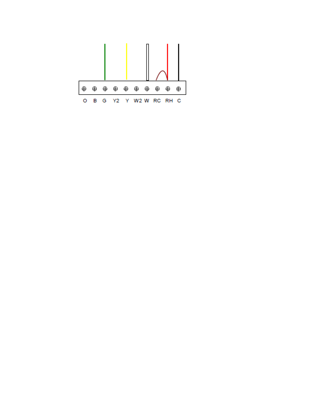
IMPORTANT
If there is only a single R, or RH wire, you will need to add a jumper
wire between RH and RC terminals on the SmartController™ wiring
terminal.
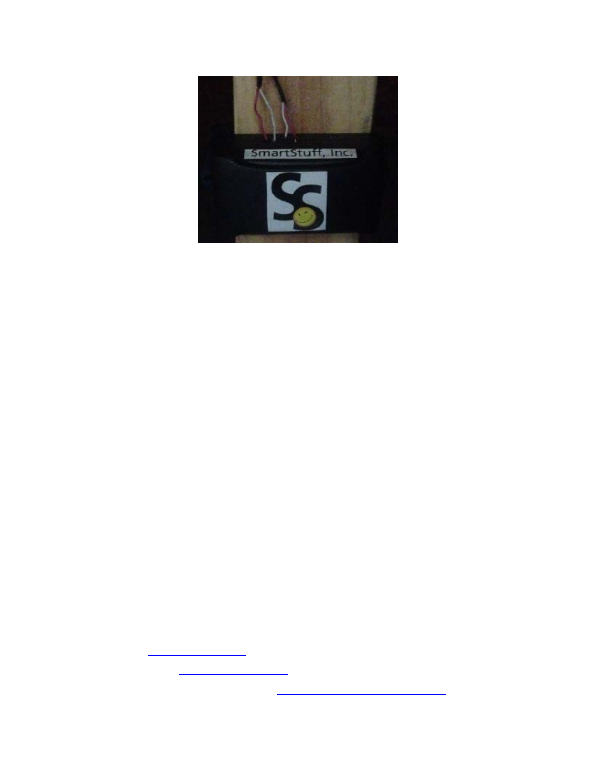
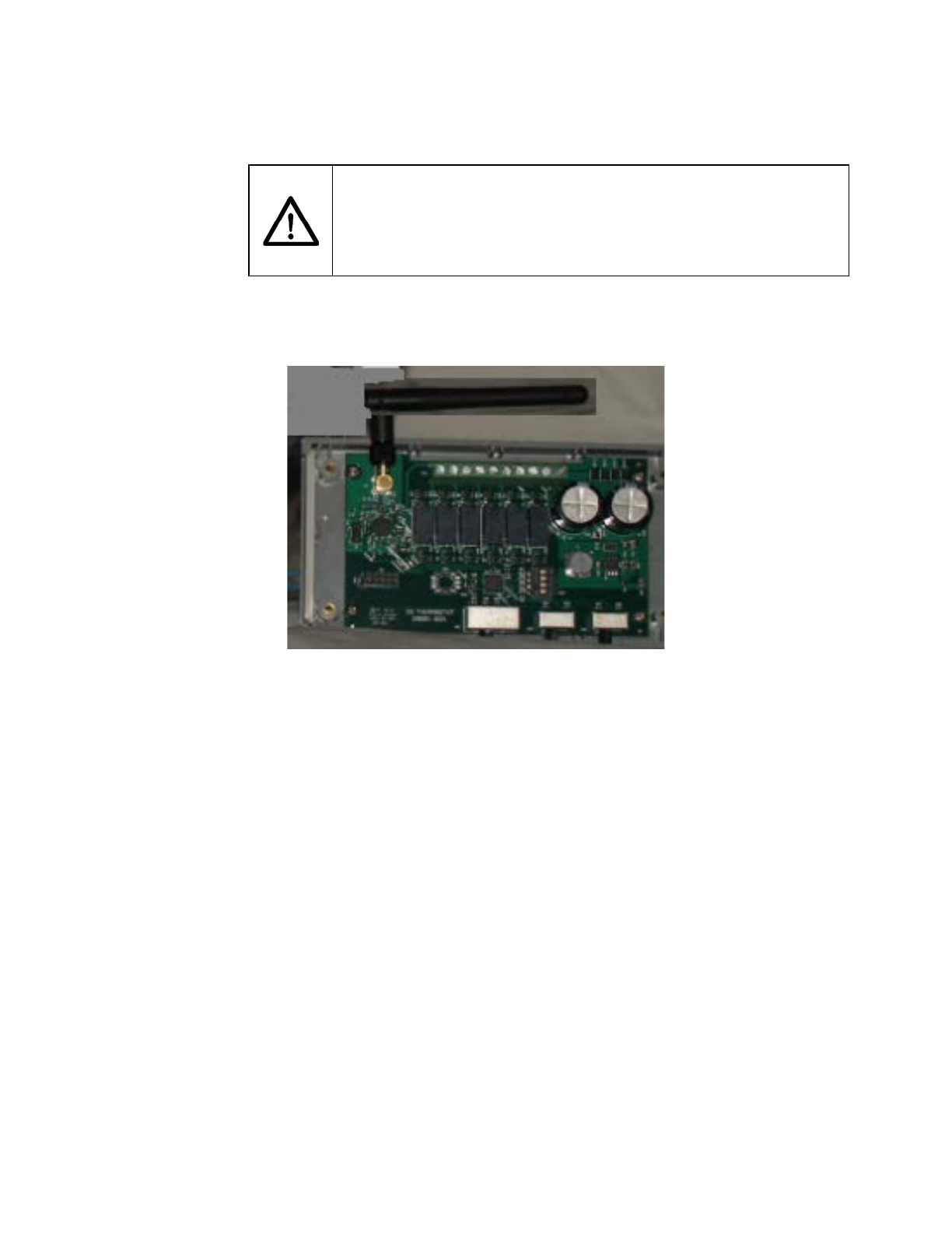
Remove the cover from the SmartController™. See the illustration below.
Route wall wires through the opening in the bottom of the SmartController™.
Attach wall wires to the corresponding position in the screw terminal block in the
SmartController™. The following diagram illustrates a typical 4-wire connection.
Illustration
6: SmartController™, cover removed
24000-01 Rev 01
Page 16
Locate the SmartController™ on the wall covering the opening for the
wires. Mark the mounting hole positions on the wall. Drill the marked
mounting positions with 3/16 drill and insert mounting anchor, if
required. Position SmartController™ over drilled holes and attach to
wall with mounting screws. Ensure thermostat wires are securely
attached in screw terminal blocks. Replace cover on
SmartController™ device.
Illustration 7:
Typical 4
-wire Heat/Cool wiring
24000-01 Rev 01
Page 17
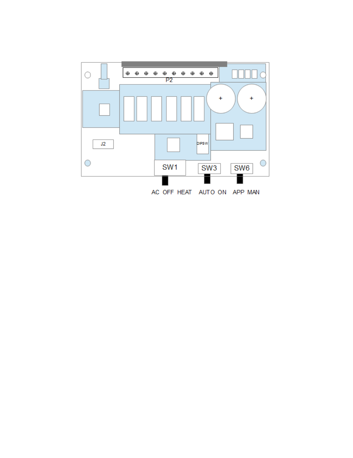
5.3 Configuration Description
The following are a description of the external switch setting of the SmartController™
device.
• SW1 – Three position switch
• AC
• OFF
• HEAT
• SW3 – Two position switch
• AUTO
• ON
• SW6 – Two position switch
• APP
• MAN

24000-01 Rev 01
Page 18
6 SmartDamper™ Installation
6.1 Introduction
The SmartDamper™ consists of two elements, Duct Insert and Damper Controller.
The electronics in the Damper Controller communicates with the SmartSensor™,
which command open or close of the Damper, and energizes the motor on the
Duct Insert to open or close the damper.
6.1.1 SmartDamper™ Power Requirements
The Duct Insert and Damper Controller are powered from a standard 110V
AC line which is connected to the included low voltage transformer. The
transformer low voltage AC output voltage is +24VAC + 20%. The Duct
Insert and Damper Controller require less than 100mA.
6.1.2 Required Tools
The required tools for Smart Damper Installation.
• Phillips screwdriver
24000-01 Rev 01
Page 19
6.2 SmartDamper™ Mounting Instructions
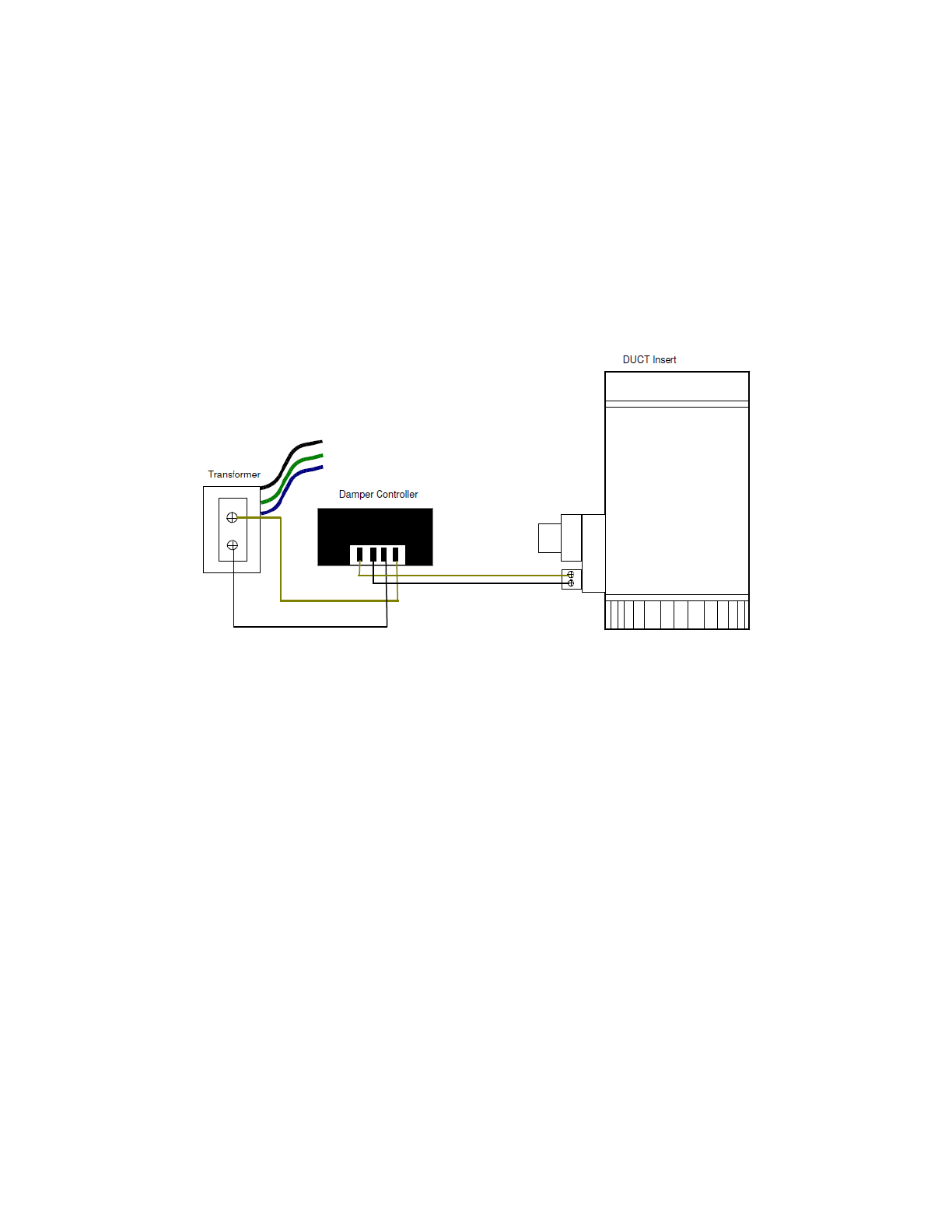
Consult the Wiring Diagram when planning the installation. Begin
by determining the location of the Duct Insert, the Damper
Controller, and the Low Voltage Transformer. Then determine the
route you will be running the wires from the Transformer to the
Damper Controller and onwards to the Duct Insert. Once you
have this planned, proceed as follows.
Illustrati
on 8: SmartDamper Wiring Diagram

24000-01 Rev 01
Page 20
6.2.1 Duct Insert Installation
For metal duct, remove a 6” (15 cm) section of duct at an
existing joint so you will have one crimped duct end and one
straight duct end. Slide the Duct Insert unit in place so that
the ends are inserted at least 1” (2.5 cm) at each end. The
Duct Insert is non-directional so it may be installed facing
either direction of the airflow. Rotate the Duct Insert so that
you can easily access the electric terminal block. Complete
the installation by securing the Duct Insert with the #6 sheet
metal screws supplied. Finish the installation by covering
the seams in the duct with a good quality aluminum foil duct
tape.
For flexible duct, cut the flexible duct and slide the ends
over the ends of the Damper unit. You will need to support
the Damper with a couple of standard duct supports
available at Home Centers. Complete the installation by
securing the Damper to the flexible duct with a good
quality aluminum foil duct tape or nylon cable ties.
6.2.2 Damper Controller Installation
Locate the Damper Controller at a convenient mounting
location within 5’ (1.5 m) from the Duct Insert.
6.2.3 Transformer installation:
IMPORTANT WARNING: Locate the breaker on your
house power panel that controls the 110/120 Volt AC
supply to the wires in the junction box that you selected to
mount the Transformer on. Use a voltage detector, Volt
Meter or other suitable instrument to make sure that all
power to that junction box is OFF. Identify an existing wiring
junction box near the location desired. Verify that the
correct wires are available in this box. There needs to be:
Black wire (line or hot), White wire (neutral) and a Green or
bare copper wire (ground). The cover plate of that junction
box must have a “knockout”. This “knockout” must be
removed to make the hole for the stud of the Transformer
to mount through. Thread the Transformer leads through
the hole and securely mount the Transformer to the cover
plate. Tighten the nut snug only. WARNING: Over-

24000-01 Rev 01
Page 21
tightening will break the plastic stud of the Transformer. DO
NOT connect the Transformer wires at this time.
6.2.4 Low voltage wiring:
Refer to the wiring diagram in Illustration: 9 for electrical
connections. It is recommended that you leave at least
1’ (30 cm) of slack wire at each component wired to
ease future servicing.
1. Run one wire from either Transformer low voltage terminal to
either of the two right most screw terminal positions on the
Damper Controller.
2. Run one wire from the other Transformer low voltage terminal
to the other of the 2 right most screw terminal positions on the
Damper Controller.
3. Run one wire from the one of the two left most screw
terminal positions on the Damper Controller to one of the
terminals on the Duct Insert.
4. Run one wire from the other of the two left most screw
terminal positions on the Dampe Controller to the remaining
therminal on the Duct Insert.
THE WIRING IS NOT POLARITY SENSITIVE
CONNECT EITHER SCREW ON TERMINAL
BLOCK OR TRANSFORMER.
6.2.5 The final steps:
1. Connect the Transformer 110/120 Volt wires inside the
junction box. See IMPORTANT WARNINGS above!
2. Connect the GREEN wire from the Transformer to the
GREEN or bare copper wire inside the junction box.
3. Connect either of the BLACK wires of the Transformer to the
WHITE wire inside the junction box.
4. Connect the remaining BLACK wire of the Transformer to the
BLACK wire inside the junction box.
5. Place the cover (with the Transformer mounted to it) on the
junction box, making sure that no wires are pinched between
the cover and the junction box.
6. Now review your installation. If you are positive that
everything has been installed safely and securely, you may
turn on the breaker on your house power panel.
24000-01 Rev 01
Page 22
7 SmartSensor™
7.1 Introduction
The following section of this manual will describe operation of the SmartSensor™
device. The SmartSensor™ is a portable control element that controls
temperature of a “sub-zone”. The SmartSensor™ includes an LCD display that
indicates the current temperature as well as the configured settings for the “sub-
zone”.
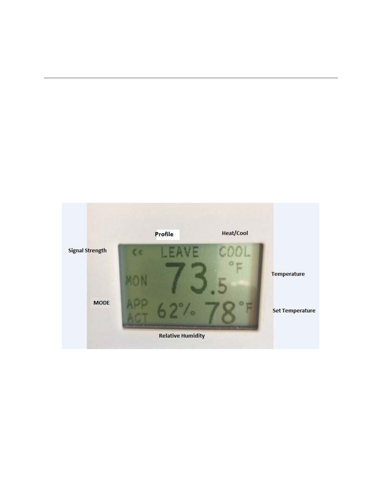
7.2 SmartSensor™ Display
The following illustration describes the fields on the SmartSensor™ display.
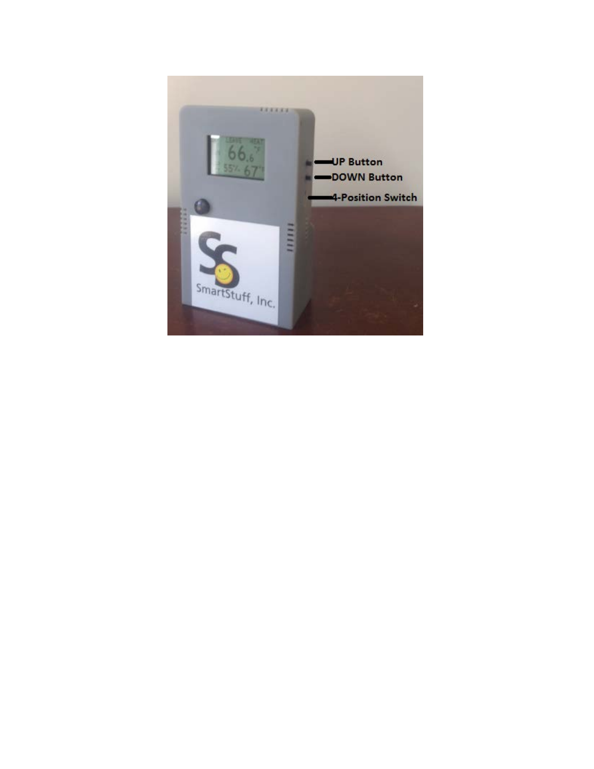
7.3 SmartSensor™Switch Description
The following illustration describes the fields on the SmartSensor™ display.
Illustration
9: SmartSensor™ LCD description
24000-01 Rev 01
Page 23
• UP Button – Manual Increase Temperature
• DOWN Button – Manual Decrease Temperature
• SWITCH – Four position switch
◦ ON
◦ OFF
◦ APP
◦ AUTO
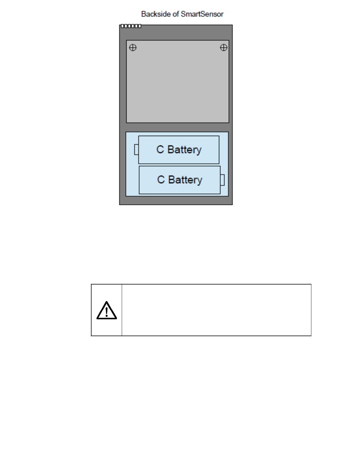
7.4 SmartSensor™ Battery Replacement Instructions
The SmartSensor™ is designed to use two C size Alkaline batteries.
The replacement of these batteries are via the removable cover on the
lower rear of the unit. The orientation of the batteries are shown in the
illustration below. The C battery polarity markings are also drawn in
the battery holder.
Illustration 10: SmartSensor™ Button Description
24000-01 Rev 01
Page 24
IMPORTANT WARNING: Improper installation of the C battery polarity will
permanently damage your SmartSensor™ unit. Take great care batteries are installed
as shown above.
WARNING
Improper installation of the C battery polarity will
permanently damage your SmartSensor™ unit. Take
great care batteries are installed as shown above.
Illustration
11: SmartSensor™ Battery
Replacement
24000-01 Rev 01
Page 25
8 VirtualZone® Smart Application
8.1 Introduction
The following section of this manual will describe operation of the VirtualZone®
Smart Application that runs on a smart phone.
The SmartSensor™ is a portable control element that controls temperature of a
“sub-zone”. The SmartSensor™ includes an LCD display that indicate the current
temperature as well as the configured settings for the “sub-zone”.
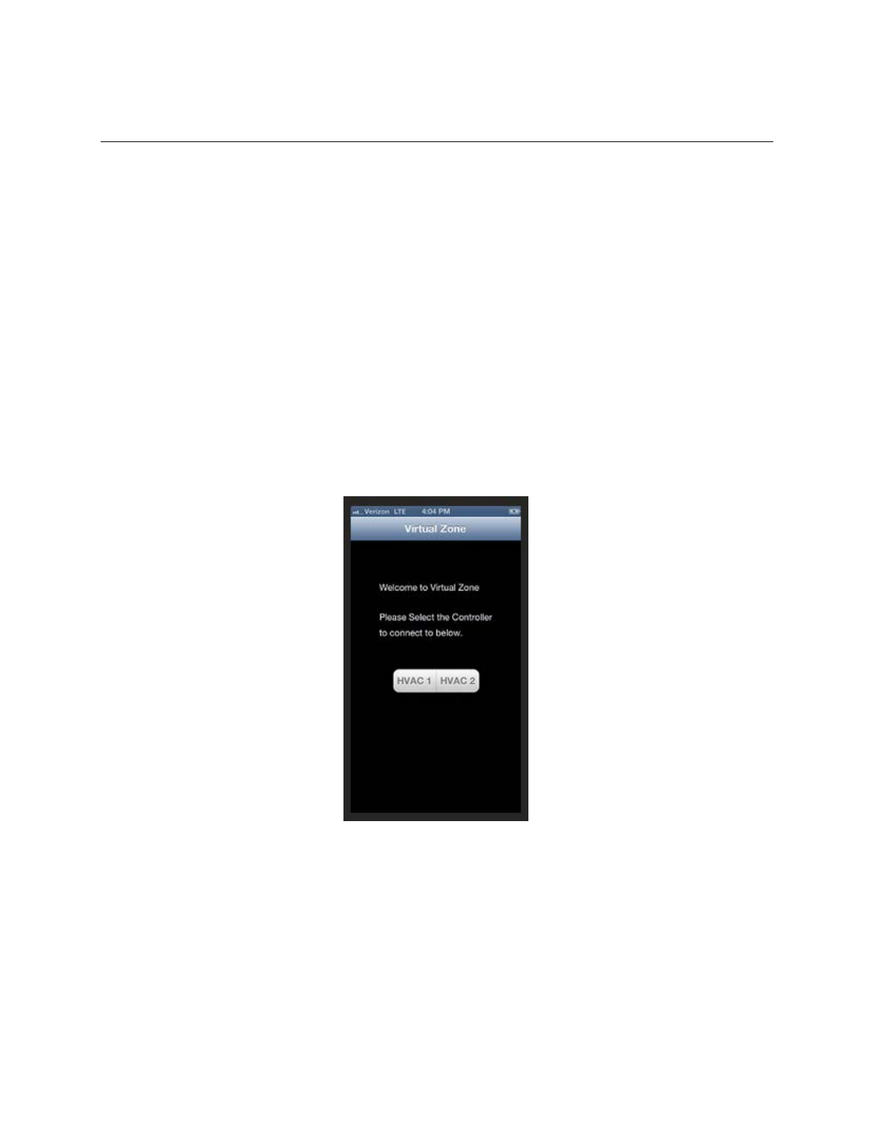
8.2 Configuration Description
The following section of this manual will describe operation of the VirtualZone®
Smart Application that runs on a smart phone.
The opening screen the user will select the particular controller to be configured.
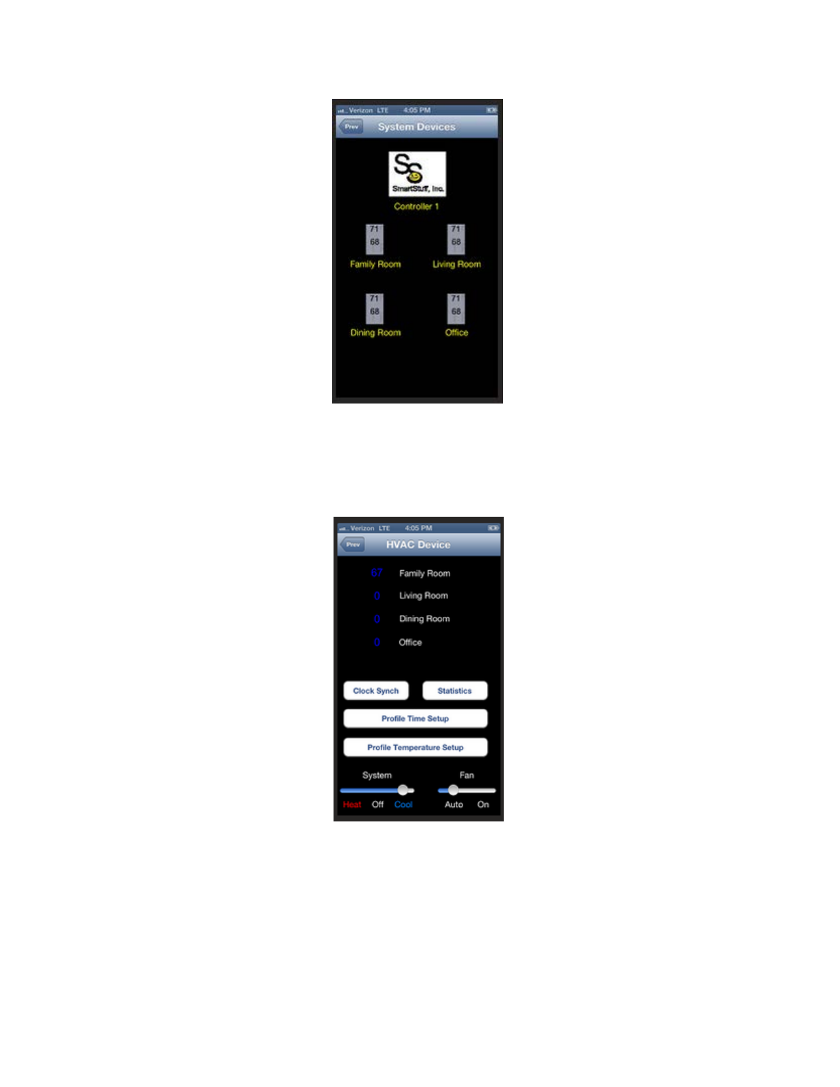
The System Devices screen display all the SmartSensor™ devices associated
with the selected SmartController™ device.
24000-01 Rev 01
Page 26
The HVAC Devices screen allows setting of HVAC Controller specific System
configuration items.
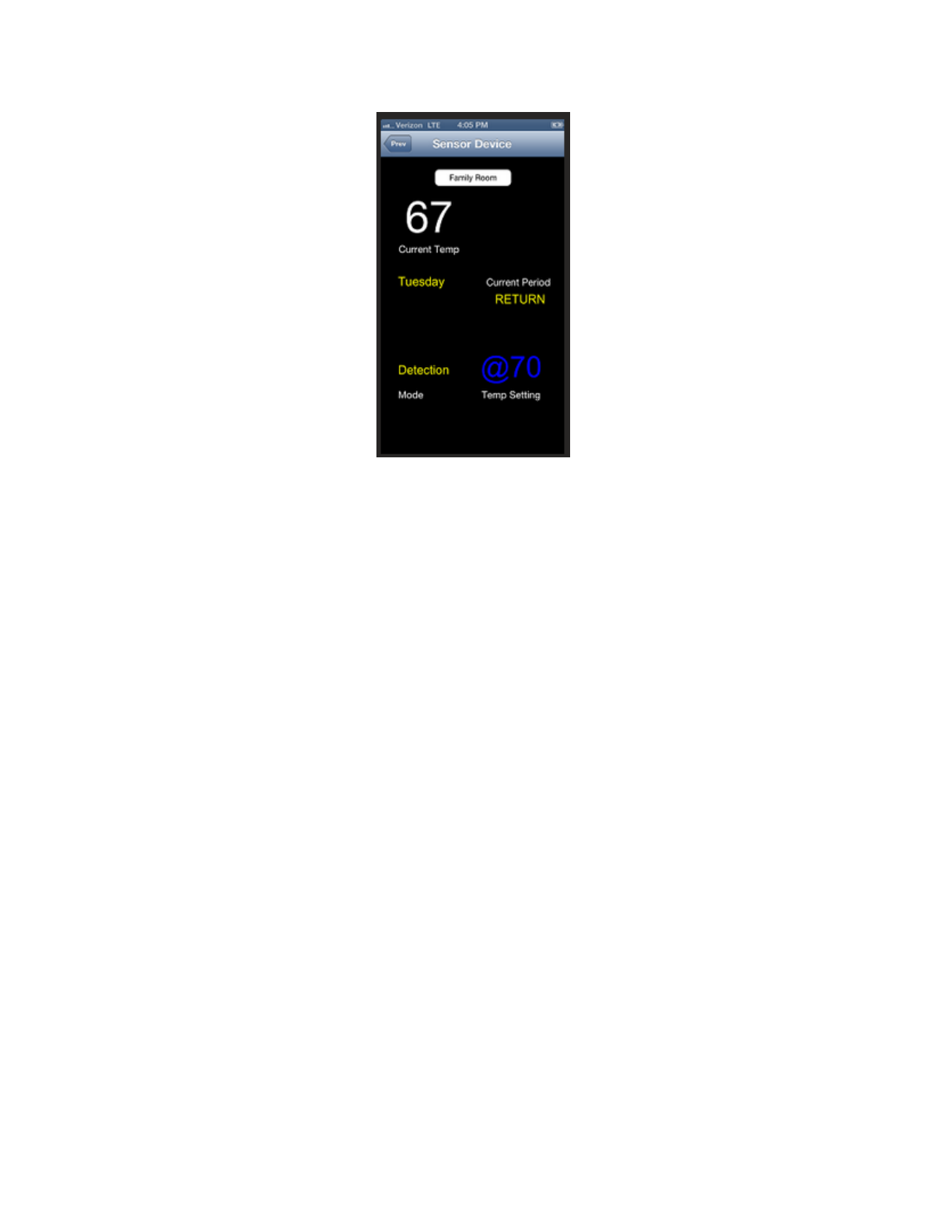
The Sensor Device screen allows setting of Sensor specific configuration items.
24000-01 Rev 01
Page 27
21135-01 Rev 01
Page 28
Appendix A SYSTEM SPECIFICATIONS
Α1 Physical Specifications
A1.1 Power Requirements
The SmartController™ and SmartDamper™ are powered by: 24 Volts
AC, 0.1 watts
CAUTION
Repair and replacement of internal cabling, circuit boards, or
components on circuit boards should only be performed using
factory-approved replacement components and procedures.
A1.2 Operating Temperature Range
VirtualZone® Zone Temperature Control
System 32°F to +122°F
(0° to 50°C)
A1.3 Storage Temperature Range
VirtualZone® Zone Temperature Control
System -4°F to +158°F
(-20° to 70°C)
A1.4 Construction Materials
• SmartController™
Electronics assemblies enclosed in plastic boxes.
Electronics assembly enclosed in extruded aluminum case with aluminum
end panels and plastic bezel.
• SmartSensor™
Electronics assemblies enclosed in plastic boxes.
• SmartDamper™ Controller
Electronics assemblies enclosed in plastic boxes.
• SmartDamper™ Duct Insert
Duct Insert is extruded aluminum case.