Smiths Detection Ireland SD-E0002 eqo Arch system for Body Scanner User Manual 95591706 Operating Instructions 11022010
Smiths Detection Ireland Limited eqo Arch system for Body Scanner 95591706 Operating Instructions 11022010
UserManual.wiki
>
Smiths Detection Ireland
>
SD E0002 User Manual
User Manual
Navigation menu
Upload a User Manual
Namespaces
Wiki Guide
HTML
PDF
Info
Views
User Manual
Discussion / Help
Navigation


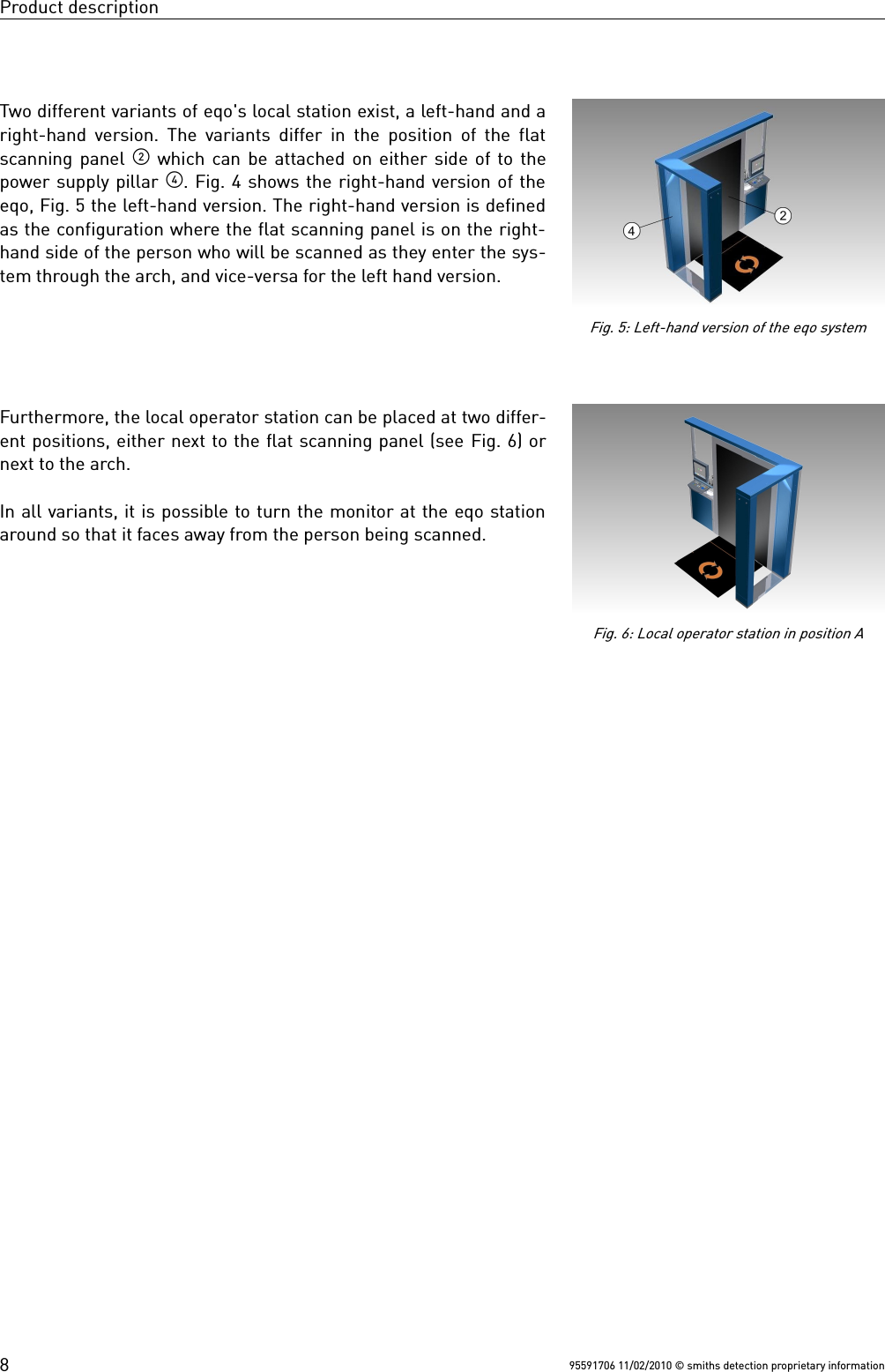
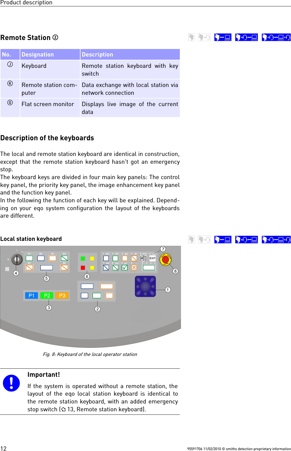
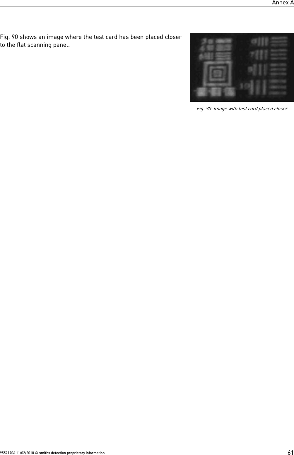
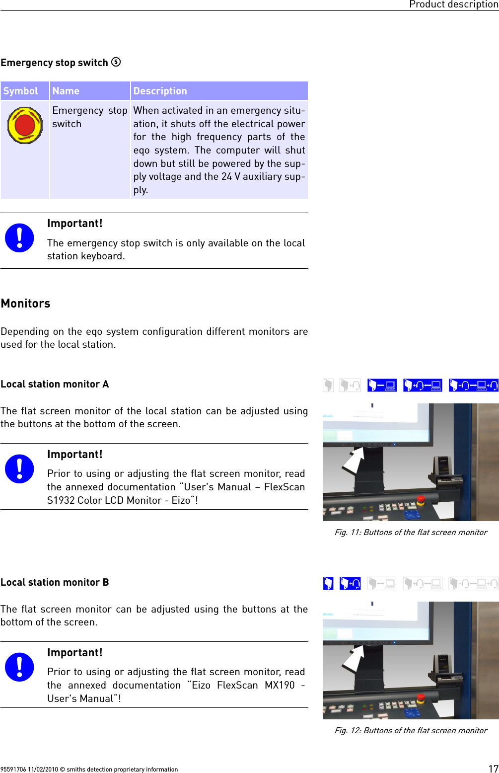
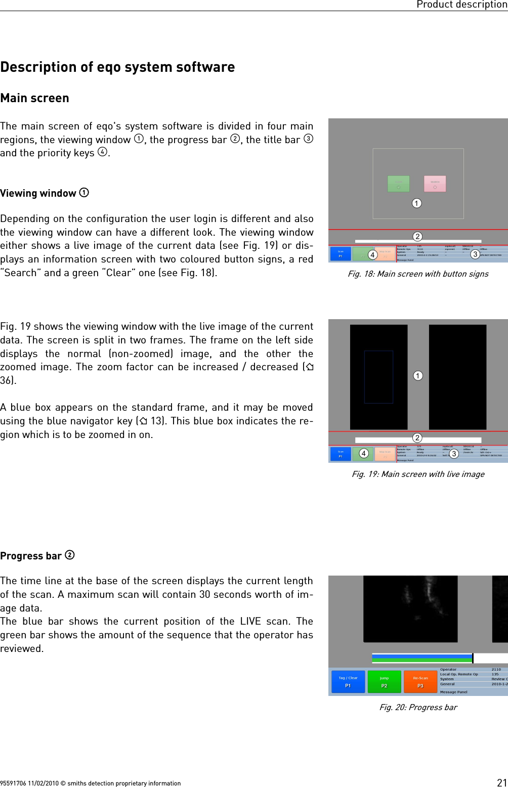
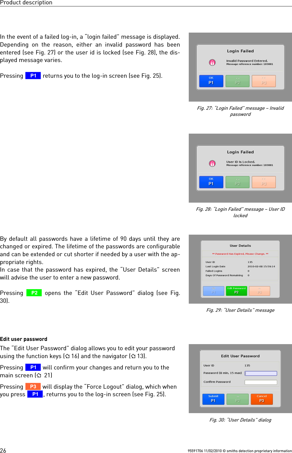
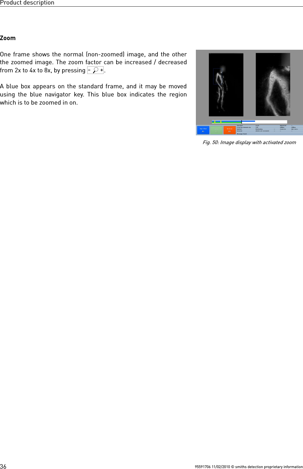
![Product descriptionImportant!The image filtering keys are disabled at the local stationfor operator's use when the eqo system is equipped witha remote station.Indicator panel Symbol Name DescriptionOperating indicator Indicates that the keyboard isprovided with power.Wait indicator Indicates that the system is notready.N/A Not enabled in this versionFunction key panel Important!Only when inside an input field the lower-case numbersand letters [1 abc] ... [0 _.] written above each functionkey are active. This gives the operator the ability to enterletters and numbers. The numbers are used by default.To switch between the entry of letters and numberspress Q / (see Fig. 10, ), Only the keys ex-plained below are available operator's use.Symbol Name DescriptionN/A Not enabled in this version.8Menu Opens the main menu9Exit Exits from the main menu to the mainscreen.N/A Not enabled in this version.N/A Not enabled in this version.QSelector Allows the operator to zoom in and out ofan area or item of interest. Zoom range isx2, x4 & x8. Clear Identifies scanned person as clean and re-turns operator station to ready state.Suspect Identifies scanned person as potentiallysuspect95591706 11/02/2010 © smiths detection proprietary information16Fig. 10: Detail of eqo's local keyboard](https://usermanual.wiki/Smiths-Detection-Ireland/SD-E0002/User-Guide-1306025-Page-22.png)
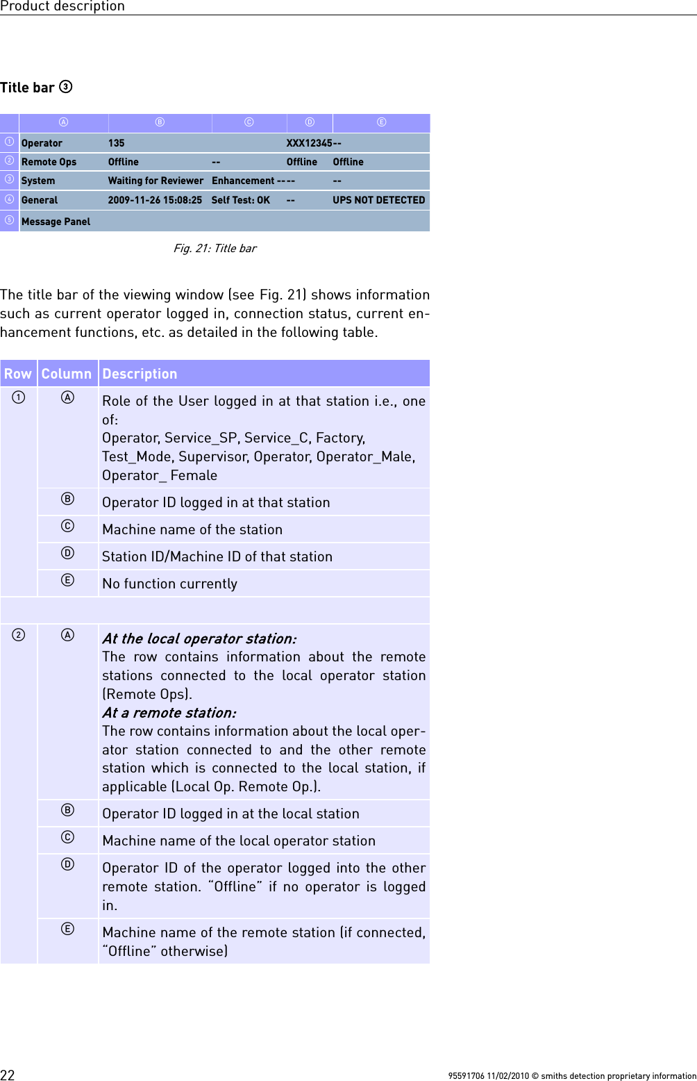
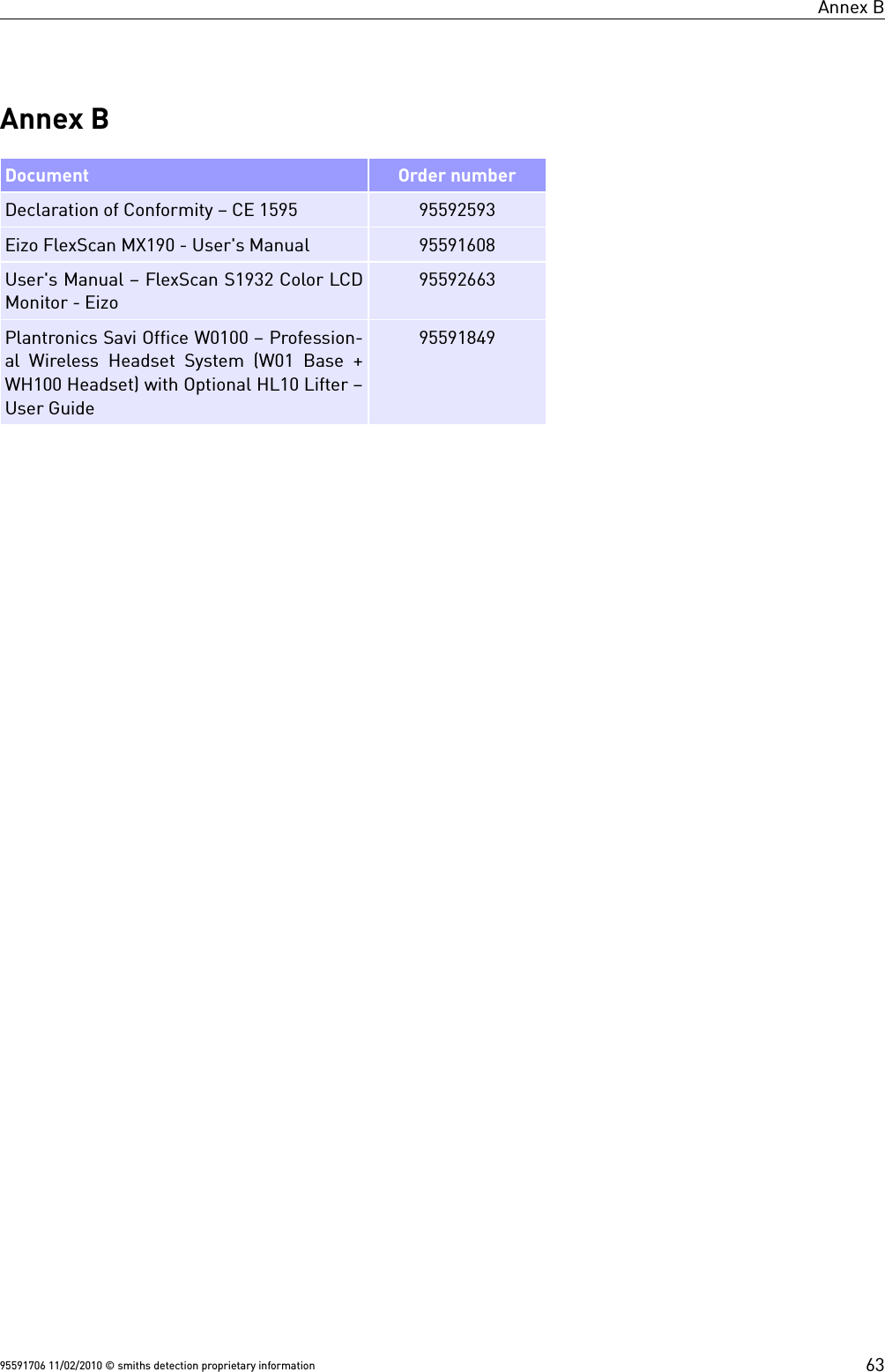
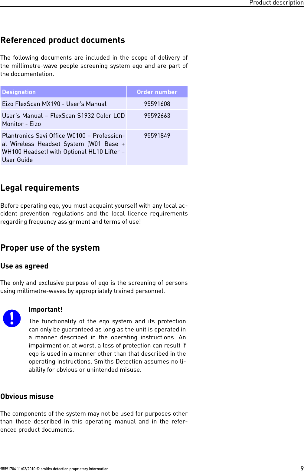
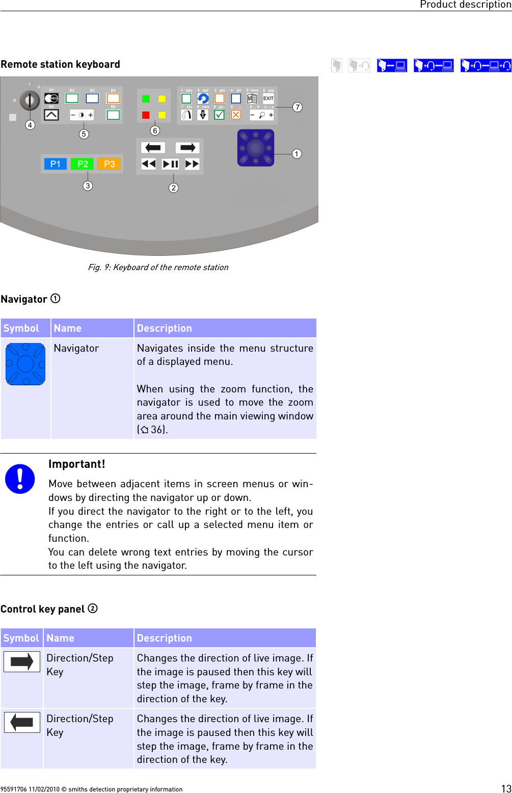
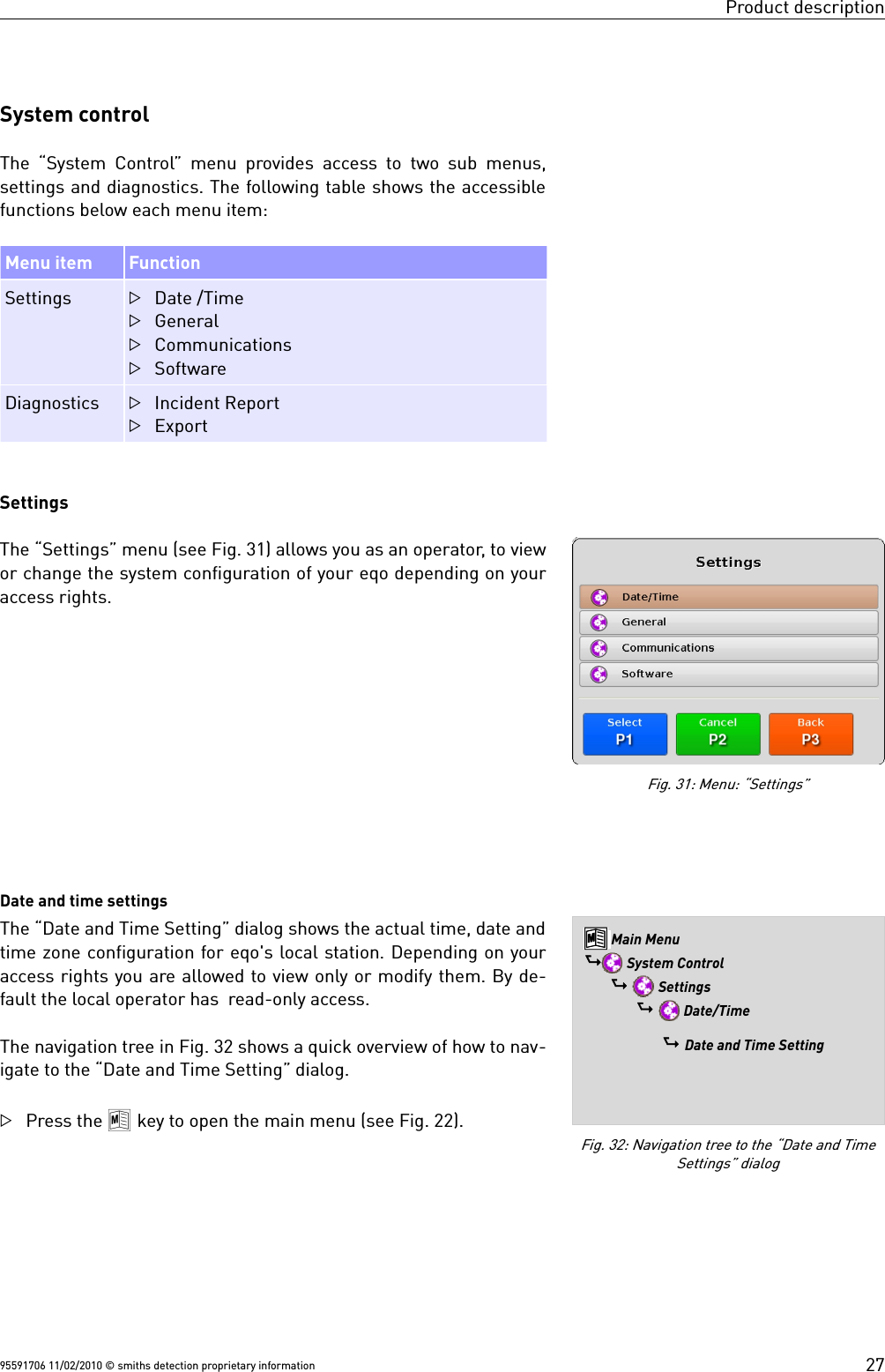
![Product descriptionConfirm the logout process by pressing T.In the case you want to cancel the logout process press U.This will bring you back to the main menu. LoginAfter the initial boot sequence or after logging out a user ( 24,chapter “ Logout“) the login screen is displayed (see Fig. 25). The default user logins are:User User role NoteOperator 135 Primarily used at the local sta-tion.246Operator male 2110 Primarily used at the remote sta-tion.Operator female 3110The login data is entered by using the function keys and the nav-igator . Fig. 26 shows a detail of the keyboard's function keys.Important!Inside an input field the lower-case numbers and letters[1 abc] ... [0 _.] written above each function key are act-ive. This gives the operator the ability to enter lettersand numbers. The numbers are used by default. Toswitch between the entry of letters and numbers press / Q.You can delete wrong text entries by moving the cursorto the left using the navigator.After a successful login, the main screen is displayed. Dependingon the user login the viewing window can have a different look (21).95591706 11/02/2010 © smiths detection proprietary informationFig. 24: Logout confirmation screenFig. 25: Login screenFig. 26: Function keys and navigator25](https://usermanual.wiki/Smiths-Detection-Ireland/SD-E0002/User-Guide-1306025-Page-31.png)
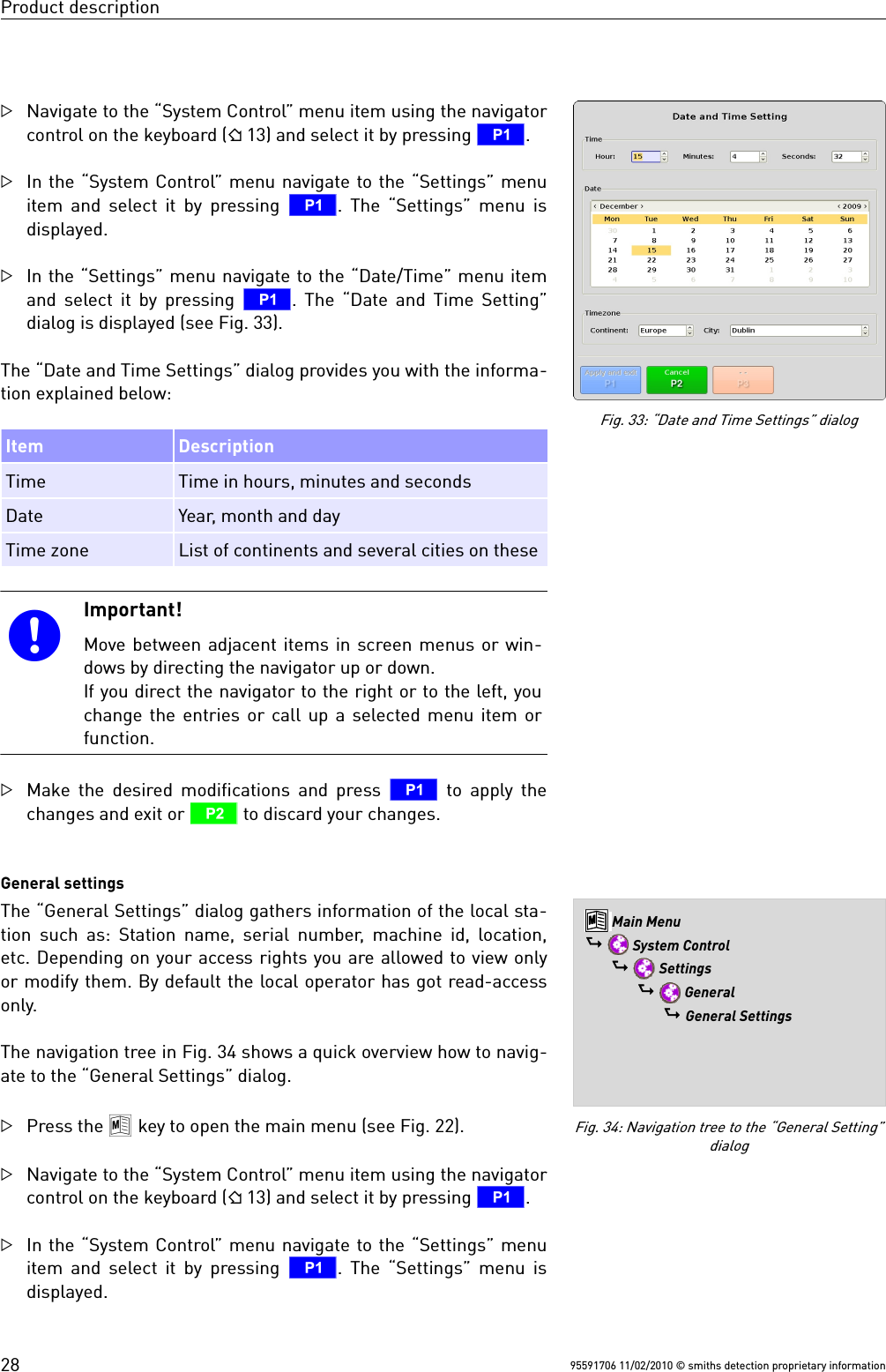
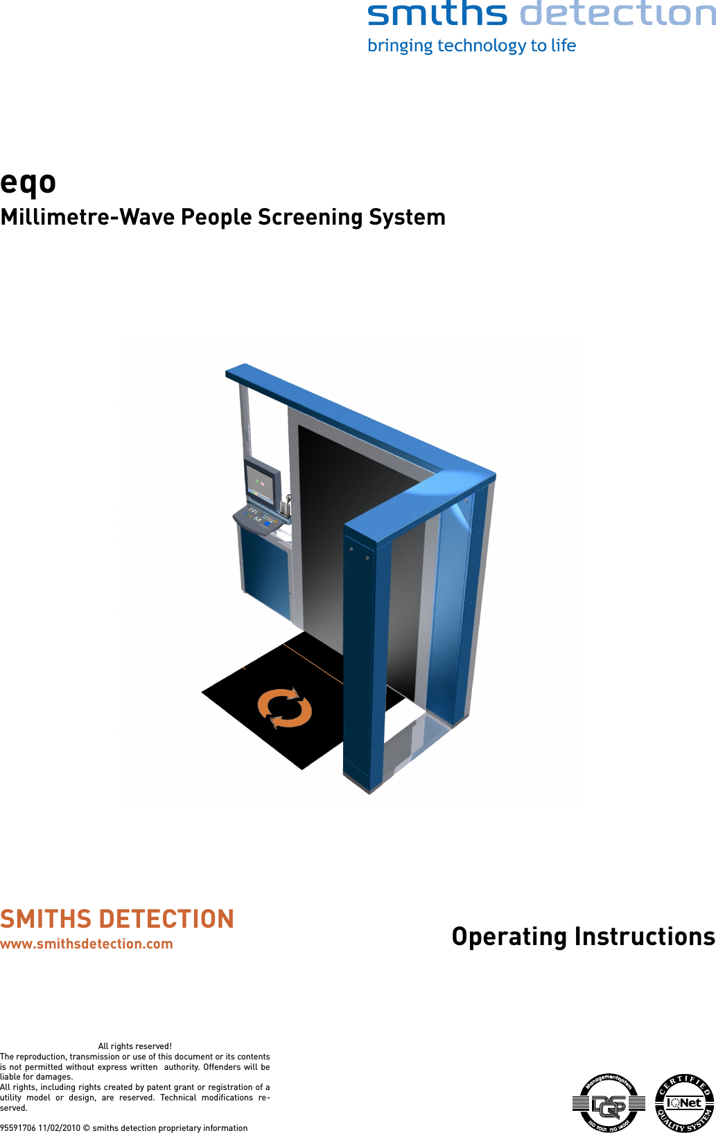
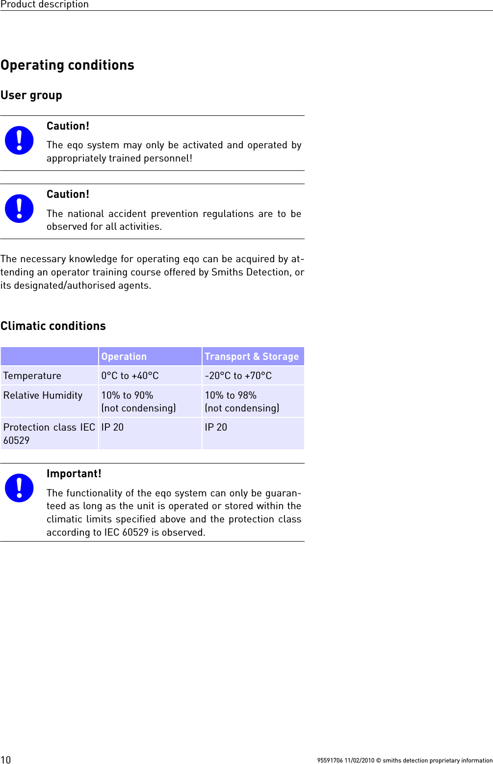
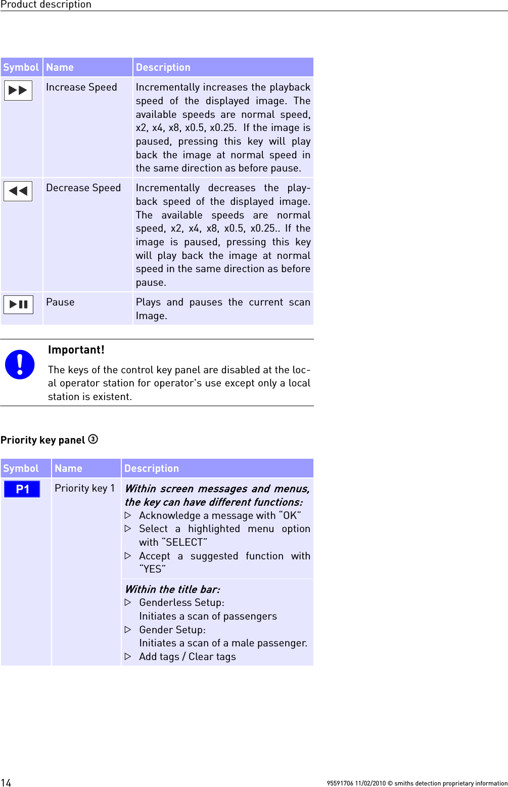
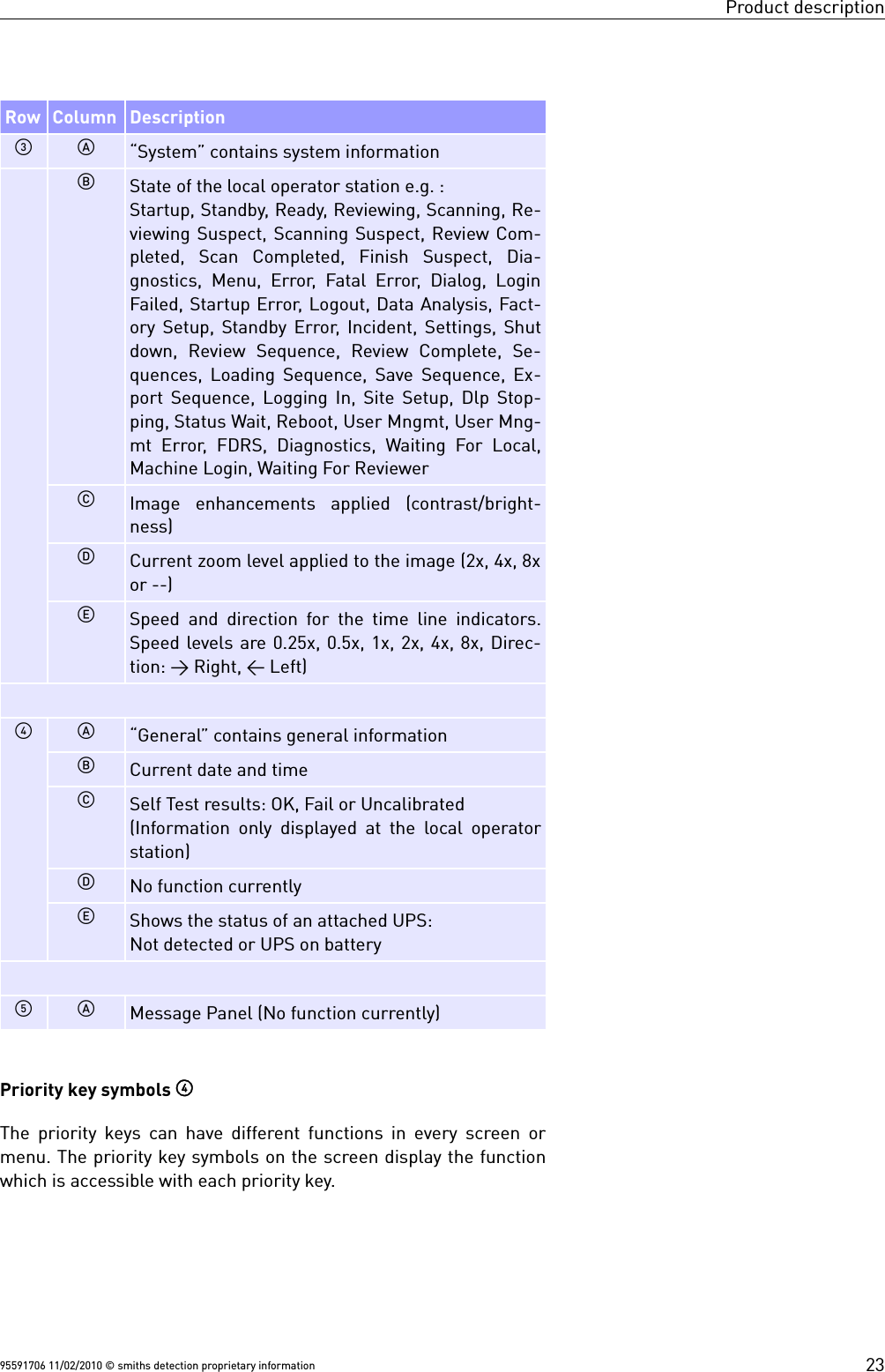
![Product descriptionIn the “Settings” menu navigate to the “General” menu item andselect it by pressing T. The “General Settings” dialog is dis-played (see Fig. 35).The “General Settings” dialog provides you with the information ex-plained below:Item DescriptionStation Name Name of the stationContractor Id Name/Id of the contractorSerial Number Serial number of stationMachine Id Machine id of the stationLocation Location of the stationSub Location Sub locations Language Change system language of the stationImportant!Move between adjacent items in screen menus or win-dows by directing the navigator up or down.If you direct the navigator to the right or to the left, youchange the entries or call up a selected menu item orfunction. Enter numbers or letters inside an input field using thefunction keys. The lower-case numbers and letters [1abc] ... [0 _.] written above each function key are active.The numbers are used by default. To switch between theentry of letters and numbers press ./ Q.Make the desired modifications and press T to apply thechanges and exit or U to discard your changes.CommunicationsThe “Communications” dialog allows you to change the IP addressof your eqo system in order to integrate your eqo system into yourlocal area network. Depending on your access rights the “Commu-nications” dialog allows you to view only or modify the IP address.By default the local operator has read-access only.The navigation tree in Fig. 36 shows a quick overview how to navig-ate to the “Communications” dialog.Press the 8 key to open the main menu (see Fig. 22).Navigate to the “System Control” menu item using the navigatorcontrol on the keyboard ( 13) and select it by pressing T. 95591706 11/02/2010 © smiths detection proprietary informationFig. 35: “General Settings” dialogFig. 36: Navigation tree to the“Communications” dialog8 Main Menu$ System Control$ Settings$ Communications$ Communications29](https://usermanual.wiki/Smiths-Detection-Ireland/SD-E0002/User-Guide-1306025-Page-35.png)
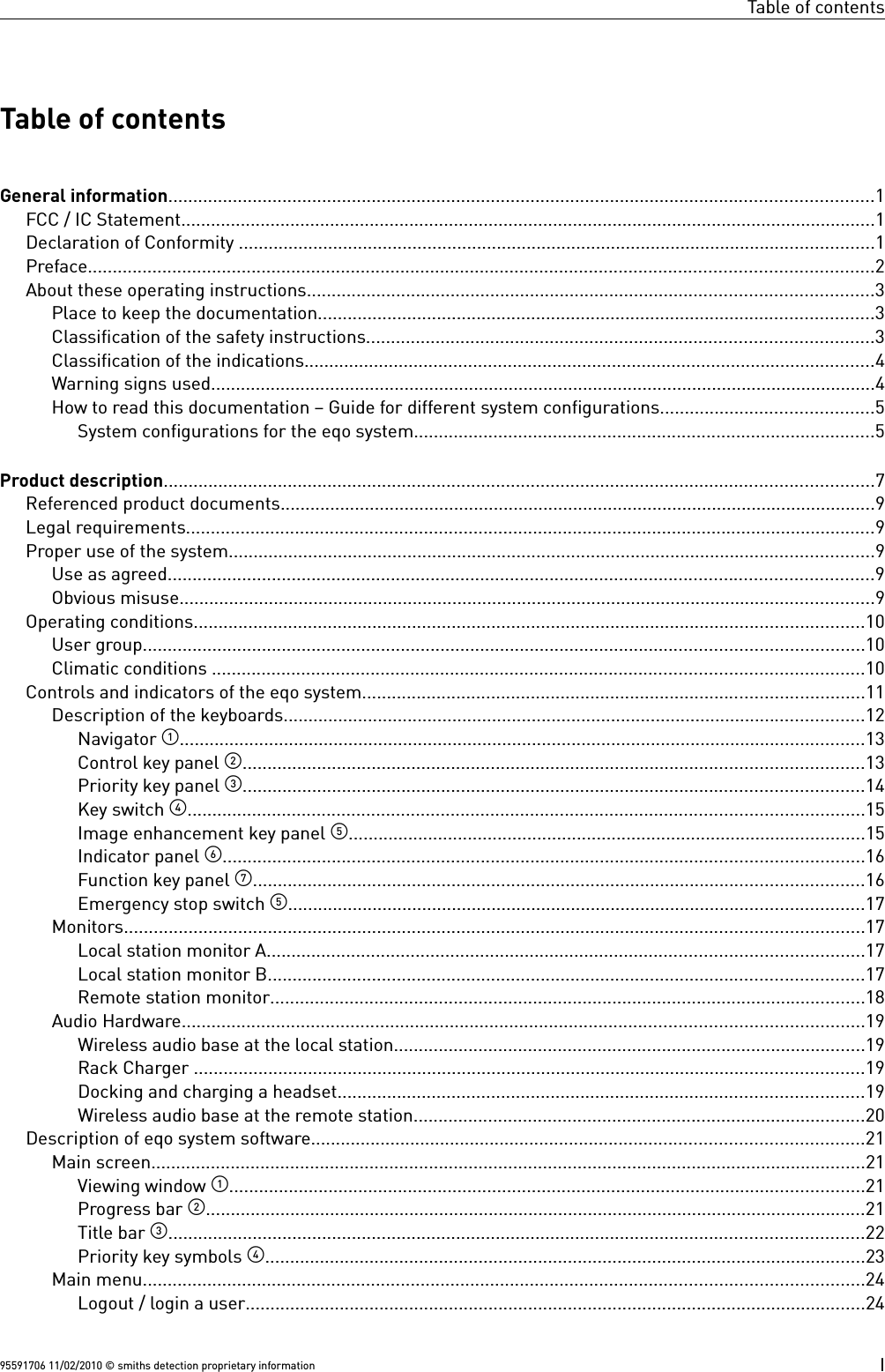
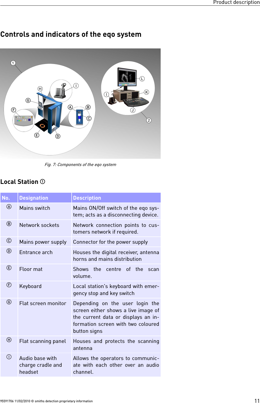
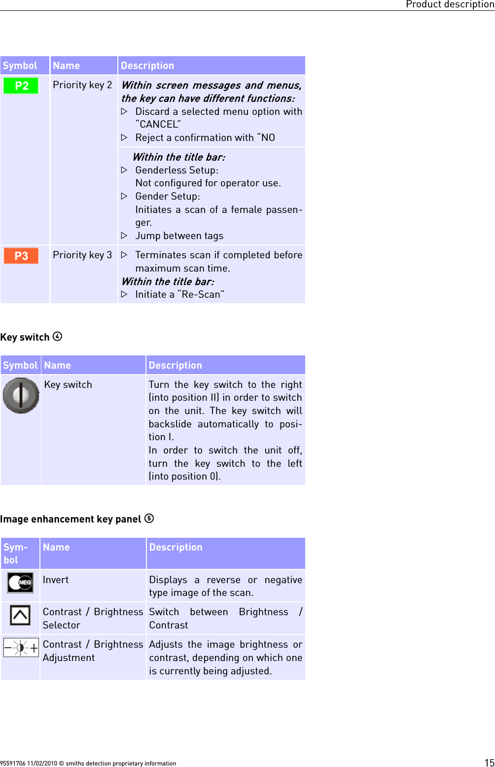
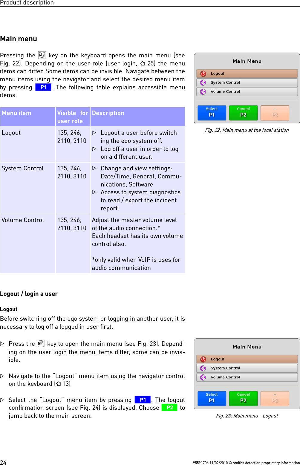
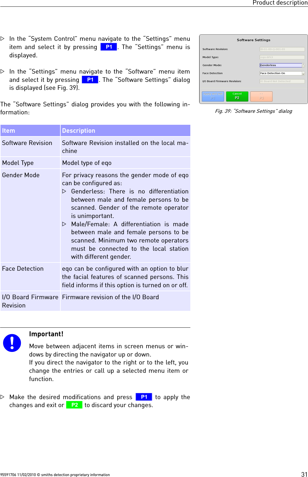
![Product descriptionIn the “System Control” menu navigate to the “Settings” menuitem and select it by pressing T. The “Settings” menu isdisplayed.In the “Settings” menu navigate to the “Communications” menuitem and select it by pressing T. The “Communications”dialog is displayed. Fig. 37 shows the “Communications” dialogat the remote station. If the system is configured only with a loc-al station the “Communications” dialog will only show the localstation IP address input field.Important!Move between adjacent items in screen menus or win-dows by directing the navigator up or down.If you direct the navigator to the right or to the left, youchange the entries or call up a selected menu item orfunction. Enter numbers or letters inside an input field using thefunction keys. The lower-case numbers and letters [1abc] ... [0 _.] written above each function key are active.The numbers are used by default. To switch between theentry of letters and numbers press ./ Q.Contact your local network administrator to obtain a valid IP ad-dresses. Enter the IP address of your local station and pressT to apply the changes or U to discard them. Software The “Software Settings” dialog gathers information about the soft-ware configurations of your local station, such as: Gender configur-ation, face detection, etc.. Depending on your access rights you are allowed to view only ormodify them. By default the local operator has got read-accessonly.The navigation tree in Fig. 38 shows a quick overview how to navig-ate to the “General Settings” dialog.Press the 8 key to open the main menu (see Fig. 22).Navigate to the “System Control” menu item using the navigatorcontrol on the keyboard ( 13) and select it by pressing T.95591706 11/02/2010 © smiths detection proprietary informationFig. 38: Navigation tree to the “SoftwareSettings” dialog8 Main Menu$ System Control$ Settings$ Software$ Software SettingsFig. 37: “Communications” dialog30](https://usermanual.wiki/Smiths-Detection-Ireland/SD-E0002/User-Guide-1306025-Page-36.png)

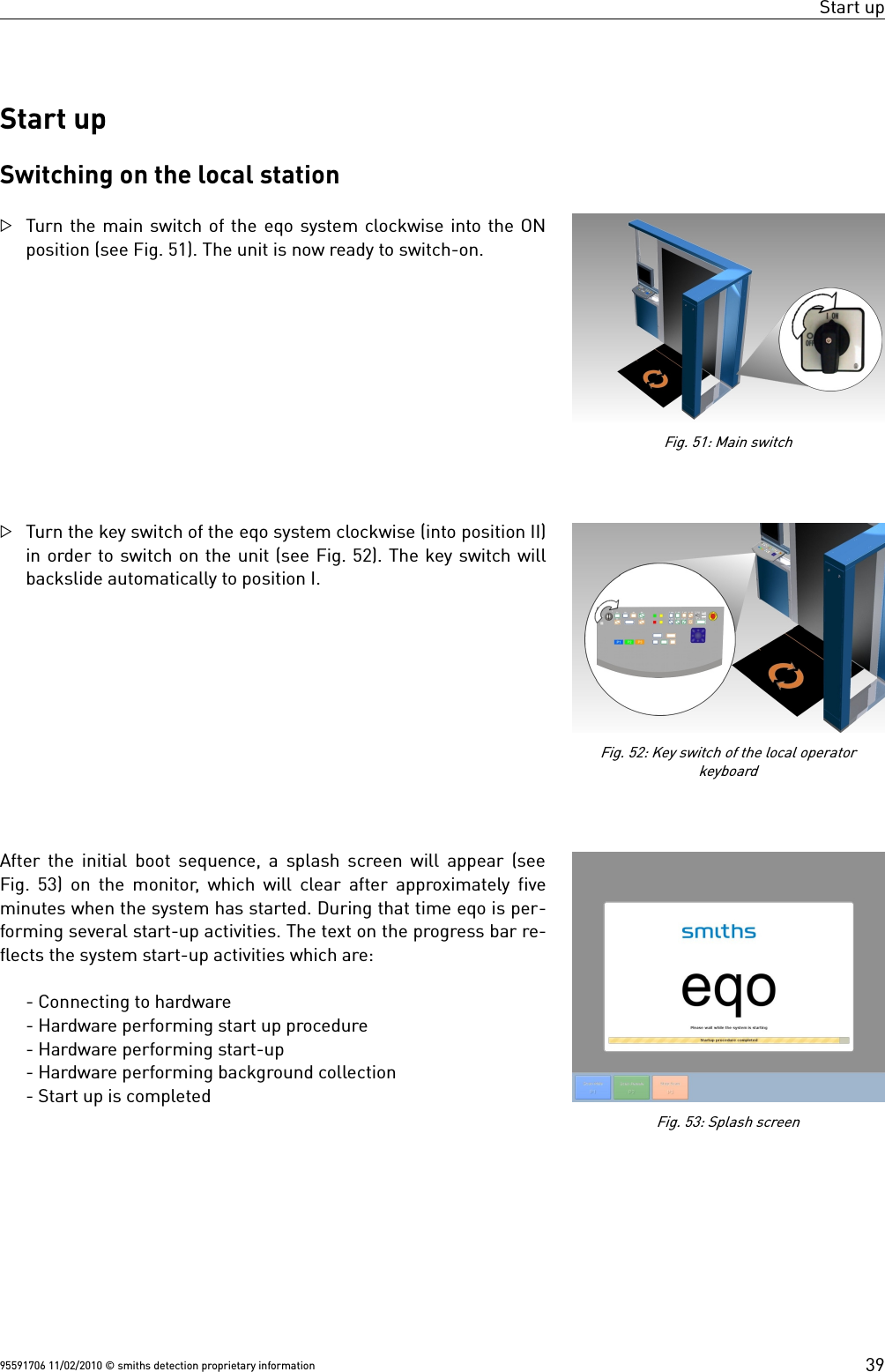
![Start upLogon to the local stationThe splash screen is followed by the login screen (see Fig. 54).Enter your login data by using the function keys and the nav-igator (see Fig. 55).Important!Inside an input field the lower-case numbers and letters[1 abc] ... [0 _.] written above each function key are act-ive. This gives the operator the ability to enter lettersand numbers. The numbers are used by default. Toswitch between the entry of letters and numbers press / Q.You can delete wrong text entries by moving the cursorto the left using the navigator.In the event of a failed log-in a “Login failed” message is displayed(see Fig. 27 and Fig. 28.on page 26). In this case press T on thekeyboard to return to the log-in screen (see Fig. 54).After a successful login, the main screen is displayed (see Fig. 56).Important!One should wait 5 minutes before performing scans, asthere is a “background collection” task initiated, whichneeds to be completed, to enable the system to prepareto capture images correctly. The scanning area shouldbe kept clear during this time, and at all times otherthan when a scan is in progress.95591706 11/02/2010 © smiths detection proprietary informationFig. 54: Login screen40Fig. 55: Function keys and navigatorFig. 56: Local operator station's main screen](https://usermanual.wiki/Smiths-Detection-Ireland/SD-E0002/User-Guide-1306025-Page-46.png)
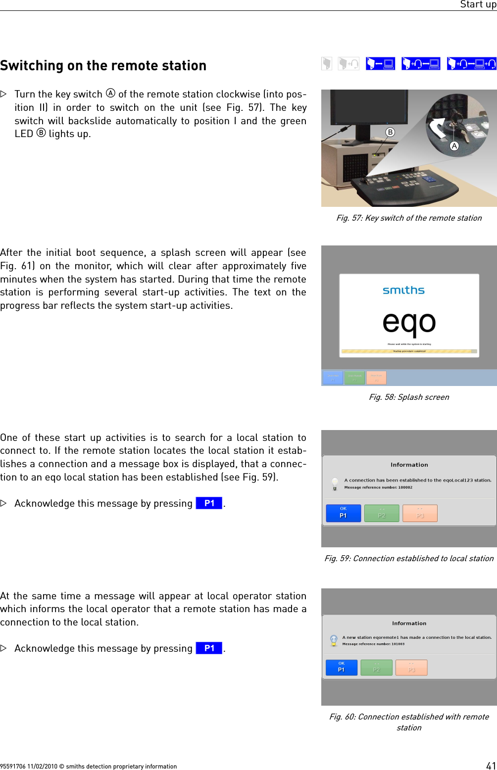
![Start upLogon to the remote stationThe splash screen is followed by the login screen (see Fig. 61).Enter your login data by using the function keys ( 13). Important!Inside an input field the lower-case numbers and letters[1 abc] ... [0 _.] written above each function key are act-ive. This gives the remote operator the ability to enterletters and numbers. The numbers are used by default.To switch between the entry of letters and numberspress Q .You can delete wrong text entries by moving the cursorto the left using the navigator.A remote login will fail if there is no connection to a local station orif a remote operator has already logged in, who is of an equivalentgender. For example if a male remote operator is logged in, then alogin at the other remote station by a male operator will fail.In the event of a failed log-in, Fig. 61 is displayed. Press Ton the keyboard to return to the log-in screen (see Fig. 61).In the event that the remote station can't find a local station a mes-sage box is displayed that the remote station failed to make a con-nection to the local station (see Fig. 62).Acknowledge this message by pressing T.After a successful login, the login information dialog will appear.This contains details about the last login date, the number of failedlogins and the number of days remaining on the password. Press-ing U the remote operator gets the ability to change the pass-word ( 26).Acknowledge this message by pressing T.95591706 11/02/2010 © smiths detection proprietary information42Fig. 61: Login screenFig. 63: Login information dialogFig. 62: Failed to connect to a local stationFig. 61: “Login Failed” screen](https://usermanual.wiki/Smiths-Detection-Ireland/SD-E0002/User-Guide-1306025-Page-48.png)