Smiths Detection Ireland SD-E0002 eqo Arch system for Body Scanner User Manual 95591706 Operating Instructions 11022010
Smiths Detection Ireland Limited eqo Arch system for Body Scanner 95591706 Operating Instructions 11022010
User Manual
eqo
Millimetre-Wave People Screening System
Operating Instructions
All rights reserved!
The reproduction, transmission or use of this document or its contents
is not permitted without express written authority. Offenders will be
liable for damages.
All rights, including rights created by patent grant or registration of a
utility model or design, are reserved. Technical modifications re-
served.
95591706 11/02/2010 © smiths detection proprietary information
SMITHS DETECTION
www.smithsdetection.com

This document contains the following modules:
95592593 Declaration of Conformity – CE 1595
95591608 Eizo FlexScan MX190 - User's Manual
95592663 User's Manual – FlexScan S1932 Color LCD Monitor - Eizo
95591849 Plantronics Savi Office W0100 – Professional Wireless Headset System (W01 Base + WH100 Headset) with Optional HL10 Lifter – User Guide
95591706 11/02/2010 © smiths detection proprietary information0

Table of contents
Table of contents
General information..............................................................................................................................................1
FCC / IC Statement............................................................................................................................................1
Declaration of Conformity ................................................................................................................................1
Preface..............................................................................................................................................................2
About these operating instructions..................................................................................................................3
Place to keep the documentation................................................................................................................3
Classification of the safety instructions......................................................................................................3
Classification of the indications...................................................................................................................4
Warning signs used......................................................................................................................................4
How to read this documentation – Guide for different system configurations...........................................5
System configurations for the eqo system.............................................................................................5
Product description...............................................................................................................................................7
Referenced product documents........................................................................................................................9
Legal requirements...........................................................................................................................................9
Proper use of the system..................................................................................................................................9
Use as agreed..............................................................................................................................................9
Obvious misuse............................................................................................................................................9
Operating conditions.......................................................................................................................................10
User group.................................................................................................................................................10
Climatic conditions ...................................................................................................................................10
Controls and indicators of the eqo system.....................................................................................................11
Description of the keyboards.....................................................................................................................12
Navigator ..........................................................................................................................................13
Control key panel .............................................................................................................................13
Priority key panel .............................................................................................................................14
Key switch ........................................................................................................................................15
Image enhancement key panel ........................................................................................................15
Indicator panel .................................................................................................................................16
Function key panel ...........................................................................................................................16
Emergency stop switch ....................................................................................................................17
Monitors.....................................................................................................................................................17
Local station monitor A........................................................................................................................17
Local station monitor B........................................................................................................................17
Remote station monitor........................................................................................................................18
Audio Hardware.........................................................................................................................................19
Wireless audio base at the local station...............................................................................................19
Rack Charger .......................................................................................................................................19
Docking and charging a headset..........................................................................................................19
Wireless audio base at the remote station...........................................................................................20
Description of eqo system software...............................................................................................................21
Main screen................................................................................................................................................21
Viewing window ................................................................................................................................21
Progress bar .....................................................................................................................................21
Title bar ............................................................................................................................................22
Priority key symbols .........................................................................................................................23
Main menu.................................................................................................................................................24
Logout / login a user.............................................................................................................................24
95591706 11/02/2010 © smiths detection proprietary information I

Table of contents
Logout..............................................................................................................................................24
Login................................................................................................................................................25
Edit user password..........................................................................................................................26
System control...........................................................................................................................................27
Settings.................................................................................................................................................27
Date and time settings....................................................................................................................27
General settings..............................................................................................................................28
Communications.............................................................................................................................29
Software ..........................................................................................................................................30
Diagnostics...........................................................................................................................................32
Incident Report................................................................................................................................32
Export the set up diagnostics...............................................................................................................33
Volume control......................................................................................................................................33
Image enhancement features....................................................................................................................35
Brightness............................................................................................................................................35
Contrast................................................................................................................................................35
Invert.....................................................................................................................................................35
Zoom.....................................................................................................................................................36
Safety instructions...............................................................................................................................................37
Safety instructions for start up.......................................................................................................................37
Safety instructions for operation....................................................................................................................37
Start up.................................................................................................................................................................39
Switching on the local station.........................................................................................................................39
Logon to the local station..........................................................................................................................40
Switching on the remote station.....................................................................................................................41
Logon to the remote station......................................................................................................................42
Audio communication.....................................................................................................................................44
Audio base at the local station only......................................................................................................44
Audio base at local and remote station................................................................................................44
Subscribing a master headset to the local station audio base station................................................45
Conference in additional headsets.......................................................................................................45
Adjusting the headset hearing volume................................................................................................46
Terminate a conference link.................................................................................................................47
Subscribing headset a master to the remote station's audio base.....................................................47
Operation..............................................................................................................................................................49
Conducting the person into the scanning area.........................................................................................49
Screening process......................................................................................................................................49
Reviewing the image sequence............................................................................................................50
Tag areas of interest........................................................................................................................51
Reviewing tags.................................................................................................................................51
Evaluation of the image sequence..................................................................................................52
Initiate a Re-Scan............................................................................................................................52
Shut-down............................................................................................................................................................55
Shut-down the local station............................................................................................................................55
Shut-down the remote station........................................................................................................................56
Technical data......................................................................................................................................................57
95591706 11/02/2010 © smiths detection proprietary information
II

Table of contents
Local Station....................................................................................................................................................57
Remote Station ...............................................................................................................................................58
Annex A................................................................................................................................................................59
Daily Test Procedure.......................................................................................................................................59
Test card example images.........................................................................................................................60
Annex B................................................................................................................................................................63
95591706 11/02/2010 © smiths detection proprietary information III

Table of contents
95591706 11/02/2010 © smiths detection proprietary information
IV

General information
General information
The products of Smiths Detection are developed and manufactured
in compliance with the essential health and safety requirements of
the European Community (EC).
Depending on the product the EC Directives are observed for
machines
low voltage
electromagnetic compatibility (EMC)
electromagnetic fields (EMF)
radio equipment (R&TTE)
and other relevant directives.
Important!
This is a Class A product. In a domestic environment this
product may cause radio interference in which case the
user may be required to take adequate measures.
FCC / IC Statement
This device complies with Part 15 of the FCC Rules.
Operation is subject to the following two conditions:
(1) this device may not cause harmful interference, and
(2) this device must accept any interference received, including
interference that may cause undesired operation.
This Category II radio communication device complies with Industry
Canada Standard RSS-310.*
Declaration of Conformity
Hereby, Smiths Detection declares that eqo is in compliance with
the essential requirements and other relevant provisions of Direct-
ive 1999/5/EC. A copy of the Declaration of Conformity can be found
in annex b of this document.
* Carrier frequencies: (24.04, 24.08, 24.12 (default), 24.16, 24.20, 24.24) GHz , RF Output Power: 0 dBm
95591706 11/02/2010 © smiths detection proprietary information 1

General information
Preface
These operating instructions will enable you, as the operator, to op-
erate the eqo system as intended.
These operating instructions do not, however, deal with the detec-
tion of objects in millimetre-wave images.
Using the functions of your eqo effectively and being able to detect
threats requires a certain degree of expertise. It is possible to ac-
quire these skills by attending an eqo operator training course.
It is recommended that you read these instructions carefully prior
to using your eqo In particular, please be sure to read the section
entitled "Safety instructions", which contains important informa-
tion concerning your safety.
95591706 11/02/2010 © smiths detection proprietary information
2
General information
About these operating instructions
Place to keep the documentation
These operating instructions along with the referenced product
documents (min. 1 copy of each) should be stored next to the oper-
ator’s workplace. This is to ensure that the operator can access at
any time the information he requires to perform his work.
Classification of the safety instructions
Danger categories
The safety instructions in this manual are subdivided into three
danger categories. These categories differ with regard to the
severity of injuries that can result from the non-compliance with
the instructions:
DANGER
Indicates a directly threatening danger. Non-compliance
leads to the most severe injuries or death!
WARNING
Indicates a possibly dangerous situation. Non-compli-
ance can lead to the most severe injuries or death!
CAUTION
Indicates a possibly dangerous situation. Non-compli-
ance can lead to slight or minor injuries!
95591706 11/02/2010 © smiths detection proprietary information 3
General information
Classification of the indications
In addition to the safety instructions, you will find the following
general notes and application tips:
Caution!
Indicates a possibly detrimental situation.
Non-compliance can lead to the damage of eqo!
Important!
Application tip or useful information for the user.
Text references
Example: ( 3) indicates a reference to page 3
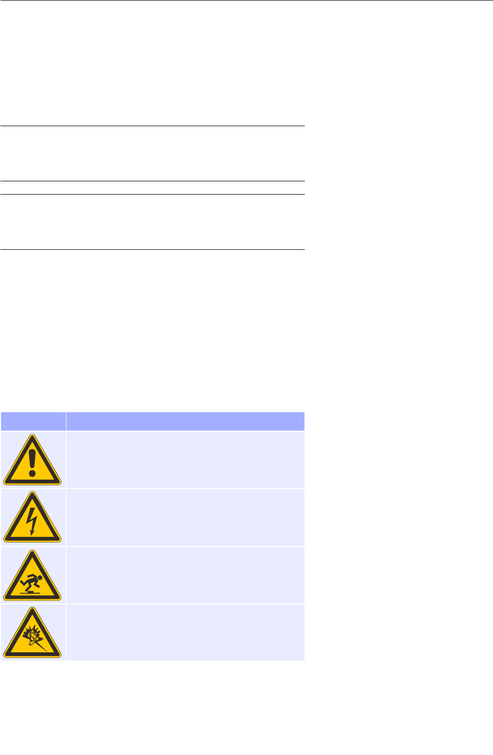
Warning signs used
Explanation of the warning signs displayed on the eqo system and
within this document.
Sign Meaning
Hazard!
Observe the instructions in the documentation!
Electric!
Panels and connectors marked by this symbol may
only be opened or used by qualified personnel with
the appropriate training!
Trip Hazard!
Danger obstacles - Watch your step!
Hearing Damage!
Indicates a potential hearing damage!
95591706 11/02/2010 © smiths detection proprietary information
4
General information
How to read this documentation – Guide for different
system configurations
The eqo system is available in different system configurations. This
documentation contains information for different system configura-
tions of the eqo system.
Each sub-chapter is clearly marked to which system configuration
it concerns. When the feature does not apply, it will simply have a
wire-frame box (grey) and no coloured (blue) fill.
Example:
If sub-chapter is marked with the following symbols,
the information containing in the sub-chapter is only concerning to
the following two configurations:
Local station only
Local station with wireless audio base and remote station
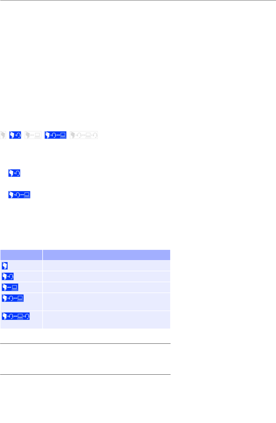
System configurations for the eqo system
In the following the possible system configurations for the eqo sys-
tem are listed:
Abbreviation Description
Local station only
Local station with wireless audio base
Local and remote station
Local station with wireless audio base and re-
mote station
Local and remote station; both with wireless au-
dio base
Important!
If a section isn’t marked, the information contained in it
is relevant for all configurations.
95591706 11/02/2010 © smiths detection proprietary information 5

General information
95591706 11/02/2010 © smiths detection proprietary information
6
Product description
Product description
eqo has been developed to enhance the capability of security
screening personnel by enabling the detection of weapons, explos-
ives, or contraband hidden under clothing using millimetre-wave
technology.
Important!
In order to protect the subject's privacy, by default, the
system is configured with local and remote station(s).
The system can be setup and operated with a local sta-
tion only (Other configurations are possible ( 5, System
configurations for the eqo system).
The operator at the local station manages the progression of the
subject through the screening process and does not have access to
the mm-wave image.
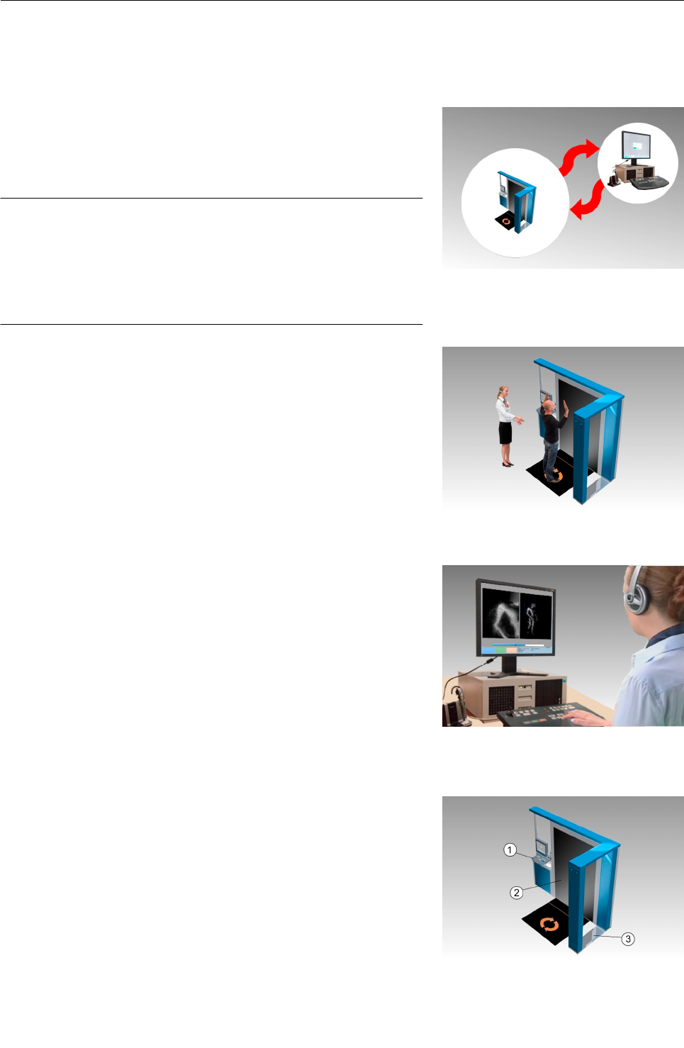
The remote operator (see Fig. 3) reviews the mm-wave image and
determines whether the subject is clear or is suspect. This de-
termination completes the review of the subject using eqo.
The eqo system consists of three main modules (see Fig. 4), the
local operator station , the flat scanning panel , and an en-
trance arch . The arch is attached at right-angles to the end of
the flat scanning panel.
95591706 11/02/2010 © smiths detection proprietary information
Fig. 4: Main components of the eqo system
Fig. 1: Local and remote station
7
Fig. 2: Person standing in screening position
Fig. 3: Remote operator reviewing the image
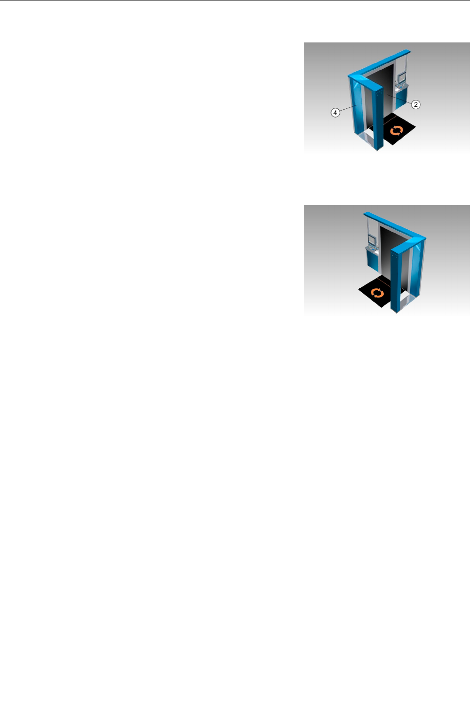
Product description
Two different variants of eqo's local station exist, a left-hand and a
right-hand version. The variants differ in the position of the flat
scanning panel which can be attached on either side of to the
power supply pillar . Fig. 4 shows the right-hand version of the
eqo, Fig. 5 the left-hand version. The right-hand version is defined
as the configuration where the flat scanning panel is on the right-
hand side of the person who will be scanned as they enter the sys-
tem through the arch, and vice-versa for the left hand version.
Furthermore, the local operator station can be placed at two differ-
ent positions, either next to the flat scanning panel (see Fig. 6) or
next to the arch.
In all variants, it is possible to turn the monitor at the eqo station
around so that it faces away from the person being scanned.
95591706 11/02/2010 © smiths detection proprietary information
Fig. 6: Local operator station in position A
Fig. 5: Left-hand version of the eqo system
8

Product description
Referenced product documents
The following documents are included in the scope of delivery of
the millimetre-wave people screening system eqo and are part of
the documentation.
Designation Order number
Eizo FlexScan MX190 - User's Manual 95591608
User's Manual – FlexScan S1932 Color LCD
Monitor - Eizo
95592663
Plantronics Savi Office W0100 – Profession-
al Wireless Headset System (W01 Base +
WH100 Headset) with Optional HL10 Lifter –
User Guide
95591849
Legal requirements
Before operating eqo, you must acquaint yourself with any local ac-
cident prevention regulations and the local licence requirements
regarding frequency assignment and terms of use!
Proper use of the system
Use as agreed
The only and exclusive purpose of eqo is the screening of persons
using millimetre-waves by appropriately trained personnel.
Important!
The functionality of the eqo system and its protection
can only be guaranteed as long as the unit is operated in
a manner described in the operating instructions. An
impairment or, at worst, a loss of protection can result if
eqo is used in a manner other than that described in the
operating instructions. Smiths Detection assumes no li-
ability for obvious or unintended misuse.
Obvious misuse
The components of the system may not be used for purposes other
than those described in this operating manual and in the refer-
enced product documents.
95591706 11/02/2010 © smiths detection proprietary information 9

Product description
Operating conditions
User group
Caution!
The eqo system may only be activated and operated by
appropriately trained personnel!
Caution!
The national accident prevention regulations are to be
observed for all activities.
The necessary knowledge for operating eqo can be acquired by at-
tending an operator training course offered by Smiths Detection, or
its designated/authorised agents.
Climatic conditions
Operation Transport & Storage
Temperature 0°C to +40°C -20°C to +70°C
Relative Humidity 10% to 90%
(not condensing)
10% to 98%
(not condensing)
Protection class IEC
60529
IP 20 IP 20
Important!
The functionality of the eqo system can only be guaran-
teed as long as the unit is operated or stored within the
climatic limits specified above and the protection class
according to IEC 60529 is observed.
95591706 11/02/2010 © smiths detection proprietary information
10
Product description
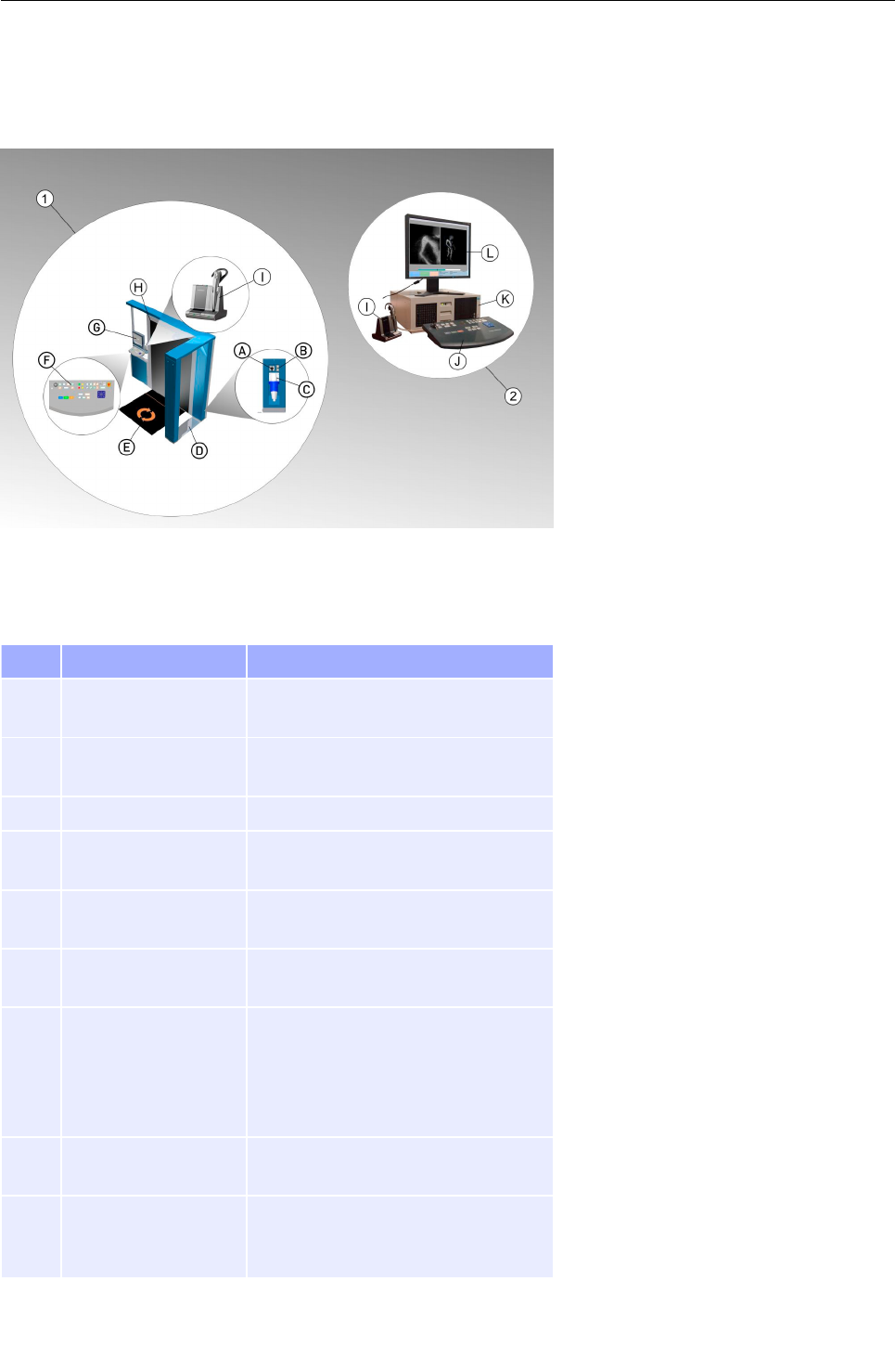
Controls and indicators of the eqo system
Local Station
No. Designation Description
Mains switch Mains ON/Off switch of the eqo sys-
tem; acts as a disconnecting device.
Network sockets Network connection points to cus-
tomers network if required.
Mains power supply Connector for the power supply
Entrance arch Houses the digital receiver, antenna
horns and mains distribution
Floor mat Shows the centre of the scan
volume.
Keyboard Local station's keyboard with emer-
gency stop and key switch
Flat screen monitor Depending on the user login the
screen either shows a live image of
the current data or displays an in-
formation screen with two coloured
button signs
Flat scanning panel Houses and protects the scanning
antenna
Audio base with
charge cradle and
headset
Allows the operators to communic-
ate with each other over an audio
channel.
95591706 11/02/2010 © smiths detection proprietary information 11
Fig. 7: Components of the eqo system
Product description
Remote Station
No. Designation Description
Keyboard Remote station keyboard with key
switch
Remote station com-
puter
Data exchange with local station via
network connection
Flat screen monitor Displays live image of the current
data
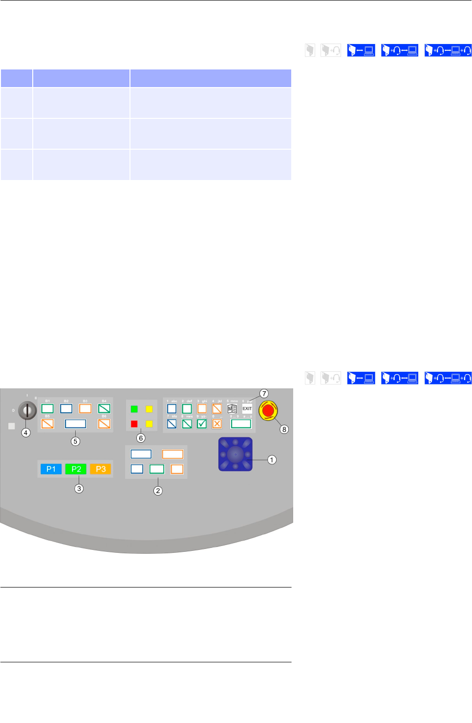
Description of the keyboards
The local and remote station keyboard are identical in construction,
except that the remote station keyboard hasn't got an emergency
stop.
The keyboard keys are divided in four main key panels: The control
key panel, the priority key panel, the image enhancement key panel
and the function key panel.
In the following the function of each key will be explained. Depend-
ing on your eqo system configuration the layout of the keyboards
are different.
Local station keyboard
Important!
If the system is operated without a remote station, the
layout of the eqo local station keyboard is identical to
the remote station keyboard, with an added emergency
stop switch ( 13, Remote station keyboard).
95591706 11/02/2010 © smiths detection proprietary information
12
Fig. 8: Keyboard of the local operator station

Product description
Remote station keyboard
Navigator
Symbol Name Description
Navigator Navigates inside the menu structure
of a displayed menu.
When using the zoom function, the
navigator is used to move the zoom
area around the main viewing window
( 36).
Important!
Move between adjacent items in screen menus or win-
dows by directing the navigator up or down.
If you direct the navigator to the right or to the left, you
change the entries or call up a selected menu item or
function.
You can delete wrong text entries by moving the cursor
to the left using the navigator.
Control key panel
Symbol Name Description
Direction/Step
Key
Changes the direction of live image. If
the image is paused then this key will
step the image, frame by frame in the
direction of the key.
Direction/Step
Key
Changes the direction of live image. If
the image is paused then this key will
step the image, frame by frame in the
direction of the key.
95591706 11/02/2010 © smiths detection proprietary information 13
Fig. 9: Keyboard of the remote station

Product description
Symbol Name Description
Increase Speed Incrementally increases the playback
speed of the displayed image. The
available speeds are normal speed,
x2, x4, x8, x0.5, x0.25. If the image is
paused, pressing this key will play
back the image at normal speed in
the same direction as before pause.
Decrease Speed Incrementally decreases the play-
back speed of the displayed image.
The available speeds are normal
speed, x2, x4, x8, x0.5, x0.25.. If the
image is paused, pressing this key
will play back the image at normal
speed in the same direction as before
pause.
Pause Plays and pauses the current scan
Image.
Important!
The keys of the control key panel are disabled at the loc-
al operator station for operator's use except only a local
station is existent.
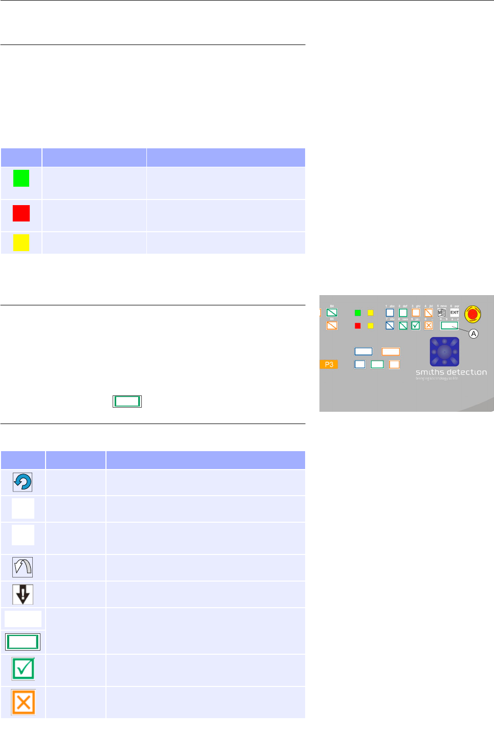
Priority key panel
Symbol Name Description
TPriority key 1
Within screen messages and menus,
the key can have different functions:
Acknowledge a message with “OK”
Select a highlighted menu option
with “SELECT”
Accept a suggested function with
“YES”
Within the title bar:
Genderless Setup:
Initiates a scan of passengers
Gender Setup:
Initiates a scan of a male passenger.
Add tags / Clear tags
95591706 11/02/2010 © smiths detection proprietary information
14

Product description
Symbol Name Description
UPriority key 2
Within screen messages and menus,
the key can have different functions:
Discard a selected menu option with
“CANCEL”
Reject a confirmation with “NO
Within the title bar:
Genderless Setup:
Not configured for operator use.
Gender Setup:
Initiates a scan of a female passen-
ger.
Jump between tags
VPriority key 3 Terminates scan if completed before
maximum scan time.
Within the title bar:
Initiate a “Re-Scan”
Key switch
Symbol Name Description
Key switch Turn the key switch to the right
(into position II) in order to switch
on the unit. The key switch will
backslide automatically to posi-
tion I.
In order to switch the unit off,
turn the key switch to the left
(into position 0).
Image enhancement key panel
Sym-
bol
Name Description
Invert Displays a reverse or negative
type image of the scan.
Contrast / Brightness
Selector
Switch between Brightness /
Contrast
Contrast / Brightness
Adjustment
Adjusts the image brightness or
contrast, depending on which one
is currently being adjusted.
95591706 11/02/2010 © smiths detection proprietary information 15
Product description
Important!
The image filtering keys are disabled at the local station
for operator's use when the eqo system is equipped with
a remote station.
Indicator panel
Symbol Name Description
Operating indicator Indicates that the keyboard is
provided with power.
Wait indicator Indicates that the system is not
ready.
N/A Not enabled in this version
Function key panel
Important!
Only when inside an input field the lower-case numbers
and letters [1 abc] ... [0 _.] written above each function
key are active. This gives the operator the ability to enter
letters and numbers. The numbers are used by default.
To switch between the entry of letters and numbers
press Q / (see Fig. 10, ), Only the keys ex-
plained below are available operator's use.
Symbol Name Description
N/A Not enabled in this version.
8Menu Opens the main menu
9Exit Exits from the main menu to the main
screen.
N/A Not enabled in this version.
N/A Not enabled in this version.
QSelector Allows the operator to zoom in and out of
an area or item of interest. Zoom range is
x2, x4 & x8.
Clear Identifies scanned person as clean and re-
turns operator station to ready state.
Suspect Identifies scanned person as potentially
suspect
95591706 11/02/2010 © smiths detection proprietary information
16
Fig. 10: Detail of eqo's local keyboard
Product description
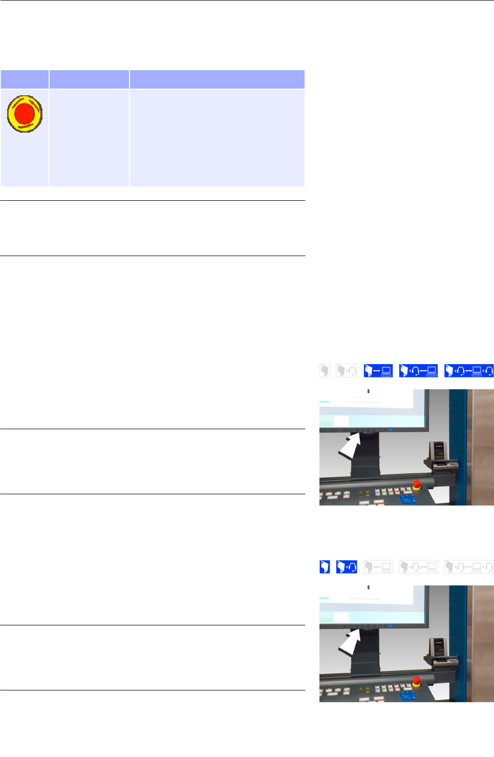
Emergency stop switch
Symbol Name Description
Emergency stop
switch
When activated in an emergency situ-
ation, it shuts off the electrical power
for the high frequency parts of the
eqo system. The computer will shut
down but still be powered by the sup-
ply voltage and the 24 V auxiliary sup-
ply.
Important!
The emergency stop switch is only available on the local
station keyboard.
Monitors
Depending on the eqo system configuration different monitors are
used for the local station.
Local station monitor A
The flat screen monitor of the local station can be adjusted using
the buttons at the bottom of the screen.
Important!
Prior to using or adjusting the flat screen monitor, read
the annexed documentation “User's Manual – FlexScan
S1932 Color LCD Monitor - Eizo“!
Local station monitor B
The flat screen monitor can be adjusted using the buttons at the
bottom of the screen.
Important!
Prior to using or adjusting the flat screen monitor, read
the annexed documentation “Eizo FlexScan MX190 -
User's Manual“!
95591706 11/02/2010 © smiths detection proprietary information
Fig. 11: Buttons of the flat screen monitor
17
Fig. 12: Buttons of the flat screen monitor

Product description
Remote station monitor
The flat screen monitor can be adjusted using the buttons at the
bottom of the screen.
Important!
Prior to using or adjusting the flat screen monitor, read
the annexed documentation “Eizo FlexScan MX190 -
User's Manual“!
95591706 11/02/2010 © smiths detection proprietary information
18
Fig. 13: Buttons of the flat screen monitor
Product description
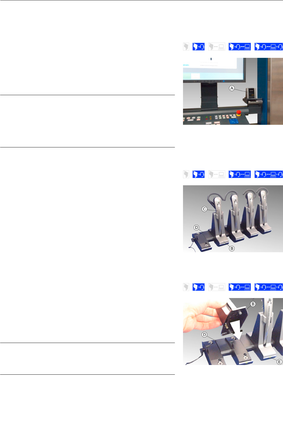
Audio Hardware
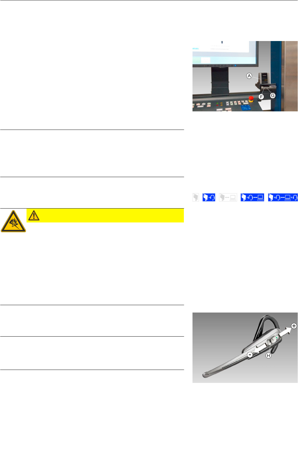
Wireless audio base at the local station
At the local station a wireless base is mounted to the keyboard
bracket (see Fig. 14). The audio hardware facilitates up to four op-
erators (remote and local operators) to conference over an audio
channel to one another.
Important!
Prior to using the audio hardware, read the annexed
documentation “Plantronics Savi Office W0100 – Profes-
sional Wireless Headset System (W01 Base + WH100
Headset) with Optional HL10 Lifter – User Guide“and
adhere to the safety instructions!
Rack Charger
For matters of industrial hygiene each operator should have its
own headset and charge cradle . The batteries of the headset
are charged by means of the rack charger . The rack charger al-
lows up to 5 headsets to be charged at one time (see Fig. 15).
Docking and charging a headset
To charge a headset, just dock the charge cradle to the rack
charger , as shown in Fig. 19, and place the headset into the
charge cradle.
When the charging indicator light turns into green the headset is
fully charged.
Important!
A full charge of the headset takes 3 hours and provide
up to 9 hours of talk time.
95591706 11/02/2010 © smiths detection proprietary information 19
Fig. 14: Wireless audio base
Fig. 15: Rack-charger
Fig. 16: Docking charge cradle to rack charger

Product description
Wireless audio base at the remote station
The base of the audio hardware is connected via USB to the remote
stations computer (see Fig. 17). The audio hardware allows the re-
mote operator to conference over an audio channel with the local
operators. The batteries of the headset are charged by means of
the rack charger (see Fig. 15).
Important!
Prior to using the audio hardware, read the annexed
documentation “Plantronics Savi Office W0100 – Profes-
sional Wireless Headset System (W01 Base + WH100
Headset) with Optional HL10 Lifter – User Guide“ and
adhere to the safety instructions!
95591706 11/02/2010 © smiths detection proprietary information
20
Fig. 17: Headset and wireless base
Product description
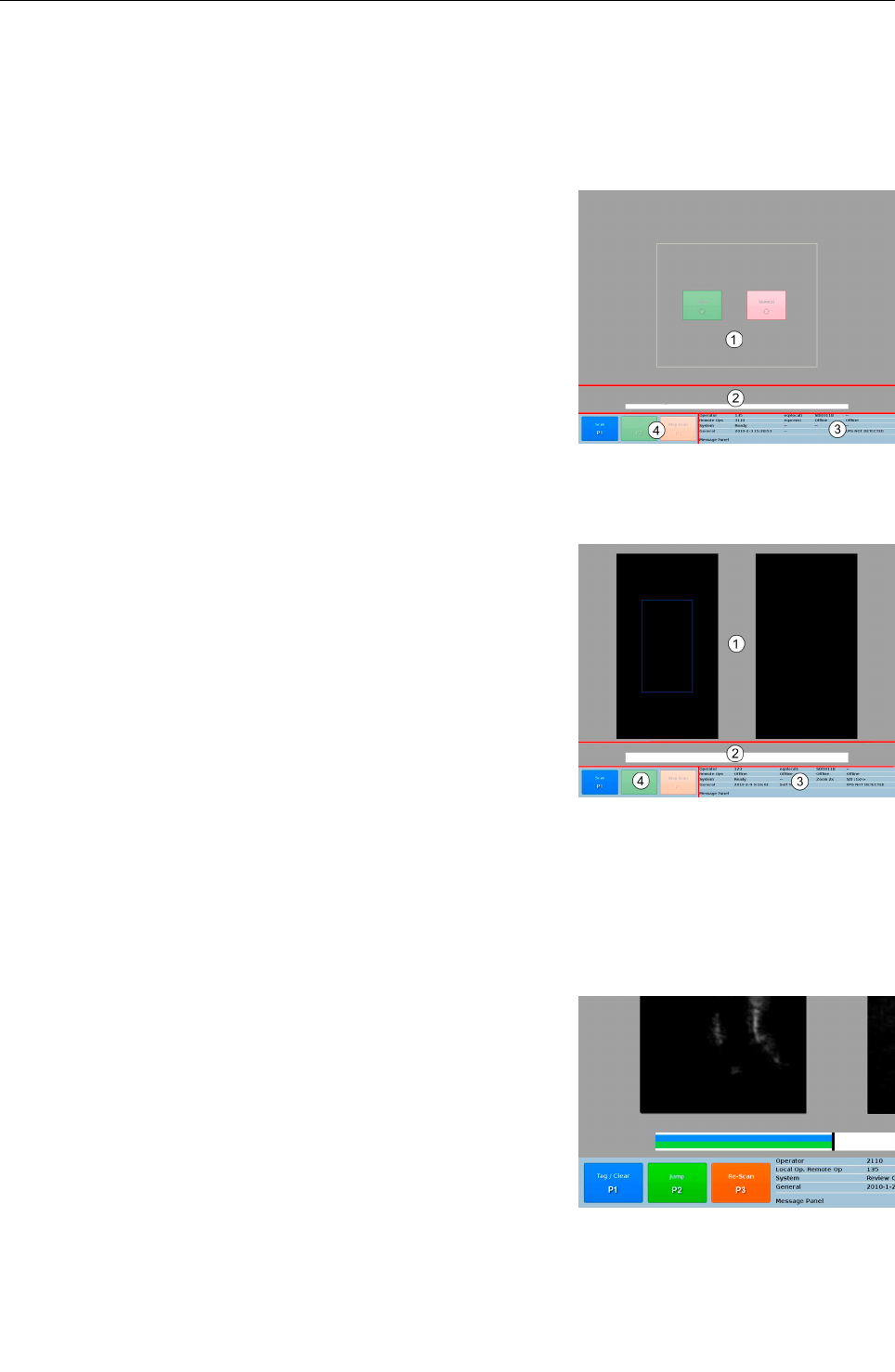
Description of eqo system software
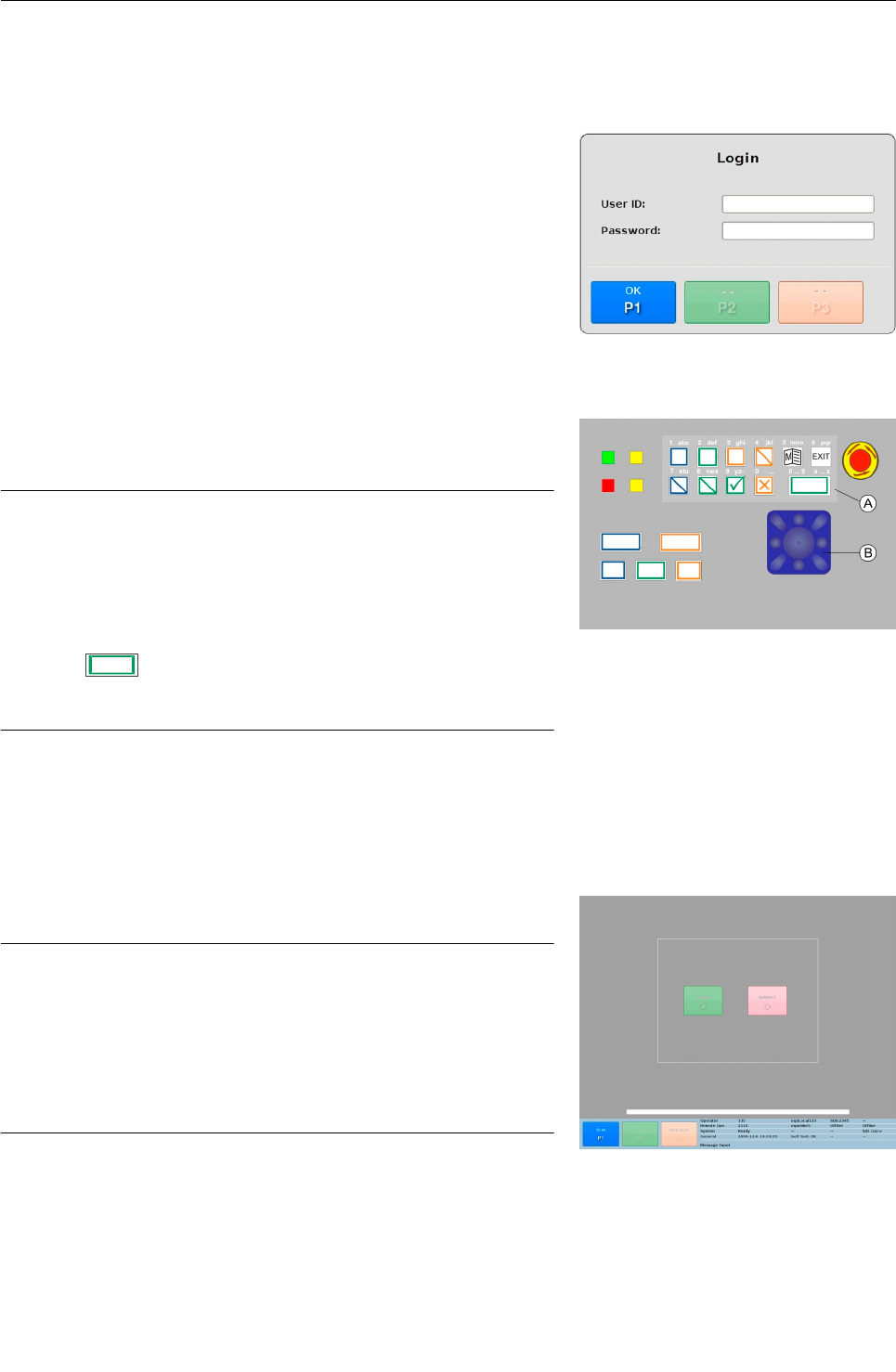
Main screen
The main screen of eqo's system software is divided in four main
regions, the viewing window , the progress bar , the title bar
and the priority keys .
Viewing window
Depending on the configuration the user login is different and also
the viewing window can have a different look. The viewing window
either shows a live image of the current data (see Fig. 19) or dis-
plays an information screen with two coloured button signs, a red
“Search” and a green “Clear” one (see Fig. 18).
Fig. 19 shows the viewing window with the live image of the current
data. The screen is split in two frames. The frame on the left side
displays the normal (non-zoomed) image, and the other the
zoomed image. The zoom factor can be increased / decreased (
36).
A blue box appears on the standard frame, and it may be moved
using the blue navigator key ( 13). This blue box indicates the re-
gion which is to be zoomed in on.
Progress bar
The time line at the base of the screen displays the current length
of the scan. A maximum scan will contain 30 seconds worth of im-
age data.
The blue bar shows the current position of the LIVE scan. The
green bar shows the amount of the sequence that the operator has
reviewed.
95591706 11/02/2010 © smiths detection proprietary information
Fig. 19: Main screen with live image
Fig. 18: Main screen with button signs
Fig. 20: Progress bar
21

Product description
Title bar
The title bar of the viewing window (see Fig. 21) shows information
such as current operator logged in, connection status, current en-
hancement functions, etc. as detailed in the following table.
Row Column Description
Role of the User logged in at that station i.e., one
of:
Operator, Service_SP, Service_C, Factory,
Test_Mode, Supervisor, Operator, Operator_Male,
Operator_ Female
Operator ID logged in at that station
Machine name of the station
Station ID/Machine ID of that station
No function currently
At the local operator station:
The row contains information about the remote
stations connected to the local operator station
(Remote Ops).
At a remote station:
The row contains information about the local oper-
ator station connected to and the other remote
station which is connected to the local station, if
applicable (Local Op. Remote Op.).
Operator ID logged in at the local station
Machine name of the local operator station
Operator ID of the operator logged into the other
remote station. “Offline” if no operator is logged
in.
Machine name of the remote station (if connected,
“Offline” otherwise)
95591706 11/02/2010 © smiths detection proprietary information
Operator 135 XXX12345--
Remote Ops Offline -- Offline Offline
System Waiting for Reviewer Enhancement ---- --
General 2009-11-26 15:08:25 Self Test: OK -- UPS NOT DETECTED
Message Panel
Fig. 21: Title bar
22

Product description
Row Column Description
“System” contains system information
State of the local operator station e.g. :
Startup, Standby, Ready, Reviewing, Scanning, Re-
viewing Suspect, Scanning Suspect, Review Com-
pleted, Scan Completed, Finish Suspect, Dia-
gnostics, Menu, Error, Fatal Error, Dialog, Login
Failed, Startup Error, Logout, Data Analysis, Fact-
ory Setup, Standby Error, Incident, Settings, Shut
down, Review Sequence, Review Complete, Se-
quences, Loading Sequence, Save Sequence, Ex-
port Sequence, Logging In, Site Setup, Dlp Stop-
ping, Status Wait, Reboot, User Mngmt, User Mng-
mt Error, FDRS, Diagnostics, Waiting For Local,
Machine Login, Waiting For Reviewer
Image enhancements applied (contrast/bright-
ness)
Current zoom level applied to the image (2x, 4x, 8x
or --)
Speed and direction for the time line indicators.
Speed levels are 0.25x, 0.5x, 1x, 2x, 4x, 8x, Direc-
tion: → Right, ← Left)
“General” contains general information
Current date and time
Self Test results: OK, Fail or Uncalibrated
(Information only displayed at the local operator
station)
No function currently
Shows the status of an attached UPS:
Not detected or UPS on battery
Message Panel (No function currently)
Priority key symbols
The priority keys can have different functions in every screen or
menu. The priority key symbols on the screen display the function
which is accessible with each priority key.
95591706 11/02/2010 © smiths detection proprietary information 23
Product description
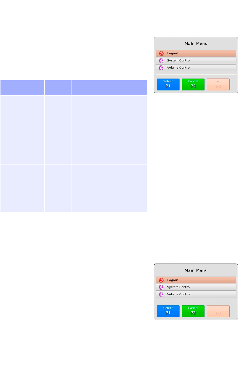
Main menu
Pressing the 8 key on the keyboard opens the main menu (see
Fig. 22). Depending on the user role (user login, 25) the menu
items can differ. Some items can be invisible. Navigate between the
menu items using the navigator and select the desired menu item
by pressing T. The following table explains accessible menu
items.
Menu item Visible for
user role
Description
Logout 135, 246,
2110, 3110
Logout a user before switch-
ing the eqo system off.
Log off a user in order to log
on a different user.
System Control 135, 246,
2110, 3110
Change and view settings:
Date/Time, General, Commu-
nications, Software
Access to system diagnostics
to read / export the incident
report.
Volume Control 135, 246,
2110, 3110
Adjust the master volume level
of the audio connection.*
Each headset has its own volume
control also.
*only valid when VoIP is uses for
audio communication
Logout / login a user
Logout
Before switching off the eqo system or logging in another user, it is
necessary to log off a logged in user first.
Press the 8 key to open the main menu (see Fig. 23). Depend-
ing on the user login the menu items differ, some can be invis-
ible.
Navigate to the “Logout” menu item using the navigator control
on the keyboard ( 13)
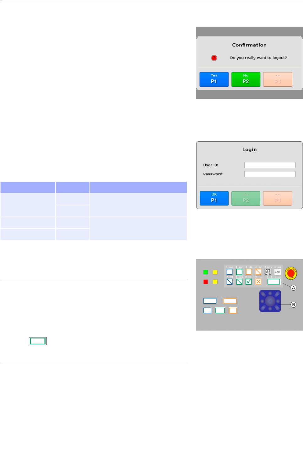
Select the “Logout” menu item by pressing T. The logout
confirmation screen (see Fig. 24) is displayed. Choose U to
jump back to the main screen.
95591706 11/02/2010 © smiths detection proprietary information
Fig. 22: Main menu at the local station
Fig. 23: Main menu - Logout
24
Product description
Confirm the logout process by pressing T.
In the case you want to cancel the logout process press U.
This will bring you back to the main menu.
Login
After the initial boot sequence or after logging out a user ( 24,
chapter “ Logout“) the login screen is displayed (see Fig. 25).
The default user logins are:
User User role Note
Operator 135 Primarily used at the local sta-
tion.
246
Operator male 2110 Primarily used at the remote sta-
tion.
Operator female 3110
The login data is entered by using the function keys and the nav-
igator . Fig. 26 shows a detail of the keyboard's function keys.
Important!
Inside an input field the lower-case numbers and letters
[1 abc] ... [0 _.] written above each function key are act-
ive. This gives the operator the ability to enter letters
and numbers. The numbers are used by default. To
switch between the entry of letters and numbers press
/ Q.
You can delete wrong text entries by moving the cursor
to the left using the navigator.
After a successful login, the main screen is displayed. Depending
on the user login the viewing window can have a different look (
21).
95591706 11/02/2010 © smiths detection proprietary information
Fig. 24: Logout confirmation screen
Fig. 25: Login screen
Fig. 26: Function keys and navigator
25
Product description
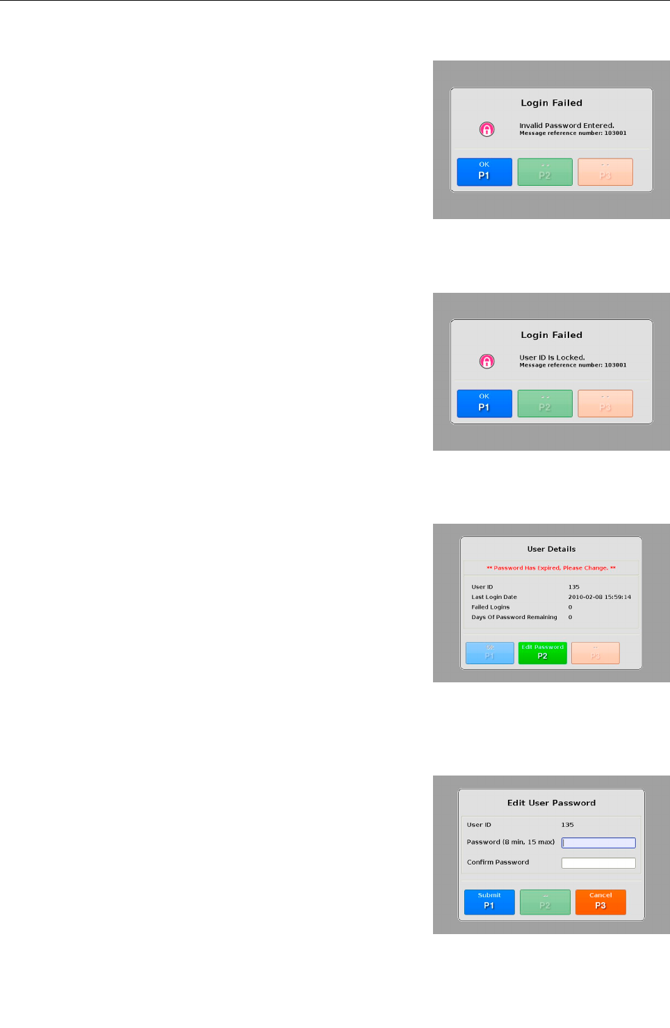
In the event of a failed log-in, a “login failed” message is displayed.
Depending on the reason, either an invalid password has been
entered (see Fig. 27) or the user id is locked (see Fig. 28), the dis-
played message varies.
Pressing T returns you to the log-in screen (see Fig. 25).
By default all passwords have a lifetime of 90 days until they are
changed or expired. The lifetime of the passwords are configurable
and can be extended or cut shorter if needed by a user with the ap-
propriate rights.
In case that the password has expired, the “User Details” screen
will advise the user to enter a new password.
Pressing U opens the “Edit User Password” dialog (see Fig.
30).
Edit user password
The “Edit User Password” dialog allows you to edit your password
using the function keys ( 16) and the navigator ( 13).
Pressing T will confirm your changes and return you to the
main screen ( 21)
Pressing V will display the “Force Logout” dialog, which when
you press T, returns you to the log-in screen (see Fig. 25).
95591706 11/02/2010 © smiths detection proprietary information
Fig. 27: “Login Failed” message – Invalid
password
26
Fig. 28: “Login Failed” message – User ID
locked
Fig. 29: “User Details” message
Fig. 30: “User Details” dialog
Product description
System control
The “System Control” menu provides access to two sub menus,
settings and diagnostics. The following table shows the accessible
functions below each menu item:
Menu item Function
Settings Date /Time
General
Communications
Software
Diagnostics Incident Report
Export
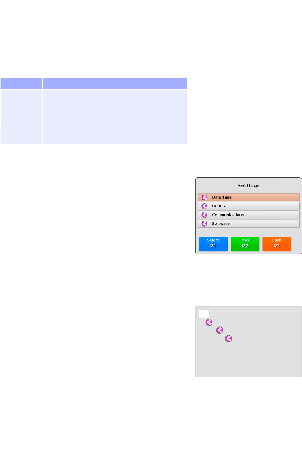
Settings
The “Settings” menu (see Fig. 31) allows you as an operator, to view
or change the system configuration of your eqo depending on your
access rights.
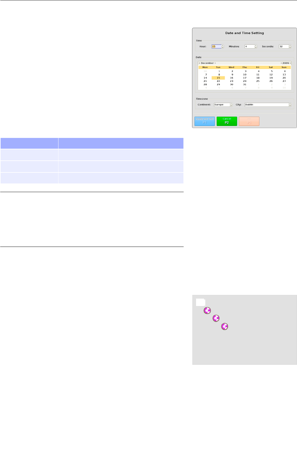
Date and time settings
The “Date and Time Setting” dialog shows the actual time, date and
time zone configuration for eqo's local station. Depending on your
access rights you are allowed to view only or modify them. By de-
fault the local operator has read-only access.
The navigation tree in Fig. 32 shows a quick overview of how to nav-
igate to the “Date and Time Setting” dialog.
Press the 8 key to open the main menu (see Fig. 22).
95591706 11/02/2010 © smiths detection proprietary information
Fig. 31: Menu: “Settings”
Fig. 32: Navigation tree to the “Date and Time
Settings” dialog
8 Main Menu
$ System Control
$ Settings
$ Date/Time
$ Date and Time Setting
27
Product description
Navigate to the “System Control” menu item using the navigator
control on the keyboard ( 13) and select it by pressing T.
In the “System Control” menu navigate to the “Settings” menu
item and select it by pressing T. The “Settings” menu is
displayed.
In the “Settings” menu navigate to the “Date/Time” menu item
and select it by pressing T. The “Date and Time Setting”
dialog is displayed (see Fig. 33).
The “Date and Time Settings” dialog provides you with the informa-
tion explained below:
Item Description
Time Time in hours, minutes and seconds
Date Year, month and day
Time zone List of continents and several cities on these
Important!
Move between adjacent items in screen menus or win-
dows by directing the navigator up or down.
If you direct the navigator to the right or to the left, you
change the entries or call up a selected menu item or
function.
Make the desired modifications and press T to apply the
changes and exit or U to discard your changes.
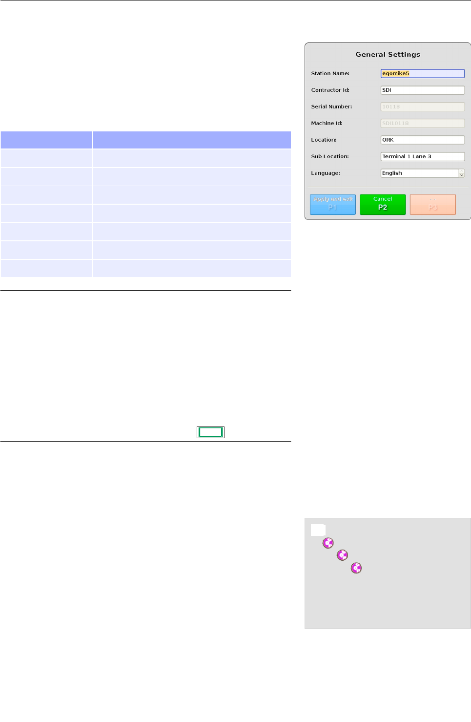
General settings
The “General Settings” dialog gathers information of the local sta-
tion such as: Station name, serial number, machine id, location,
etc. Depending on your access rights you are allowed to view only
or modify them. By default the local operator has got read-access
only.
The navigation tree in Fig. 34 shows a quick overview how to navig-
ate to the “General Settings” dialog.
Press the 8 key to open the main menu (see Fig. 22).
Navigate to the “System Control” menu item using the navigator
control on the keyboard ( 13) and select it by pressing T.
In the “System Control” menu navigate to the “Settings” menu
item and select it by pressing T. The “Settings” menu is
displayed.
95591706 11/02/2010 © smiths detection proprietary information
Fig. 34: Navigation tree to the “General Setting”
dialog
8 Main Menu
$ System Control
$ Settings
$ General
$ General Settings
Fig. 33: “Date and Time Settings” dialog
28
Product description
In the “Settings” menu navigate to the “General” menu item and
select it by pressing T. The “General Settings” dialog is dis-
played (see Fig. 35).
The “General Settings” dialog provides you with the information ex-
plained below:
Item Description
Station Name Name of the station
Contractor Id Name/Id of the contractor
Serial Number Serial number of station
Machine Id Machine id of the station
Location Location of the station
Sub Location Sub locations
Language Change system language of the station
Important!
Move between adjacent items in screen menus or win-
dows by directing the navigator up or down.
If you direct the navigator to the right or to the left, you
change the entries or call up a selected menu item or
function.
Enter numbers or letters inside an input field using the
function keys. The lower-case numbers and letters [1
abc] ... [0 _.] written above each function key are active.
The numbers are used by default. To switch between the
entry of letters and numbers press ./ Q.
Make the desired modifications and press T to apply the
changes and exit or U to discard your changes.
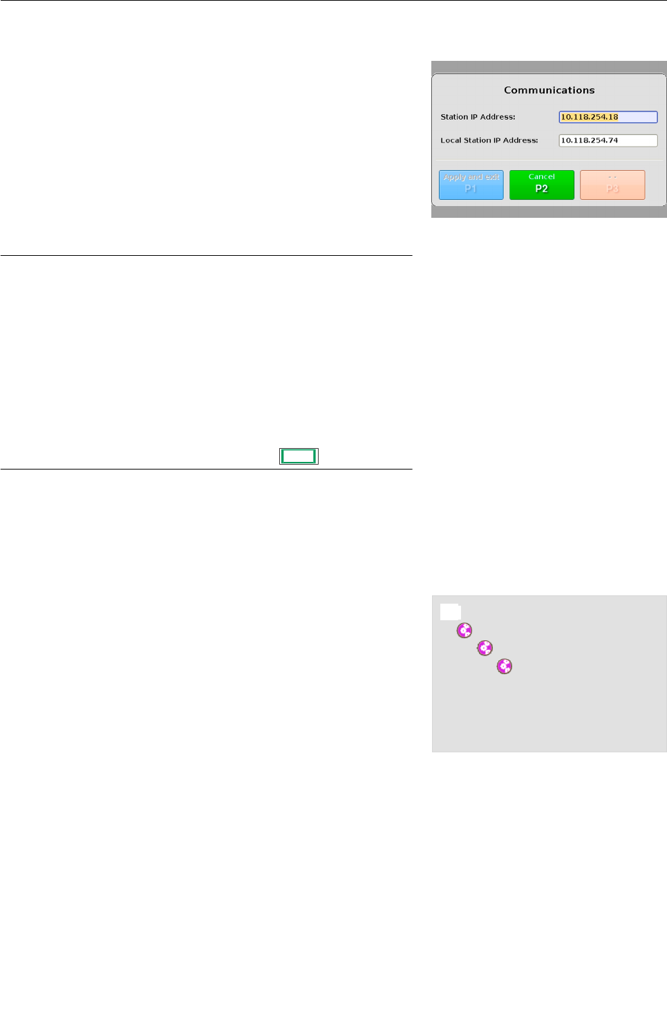
Communications
The “Communications” dialog allows you to change the IP address
of your eqo system in order to integrate your eqo system into your
local area network. Depending on your access rights the “Commu-
nications” dialog allows you to view only or modify the IP address.
By default the local operator has read-access only.
The navigation tree in Fig. 36 shows a quick overview how to navig-
ate to the “Communications” dialog.
Press the 8 key to open the main menu (see Fig. 22).
Navigate to the “System Control” menu item using the navigator
control on the keyboard ( 13) and select it by pressing T.
95591706 11/02/2010 © smiths detection proprietary information
Fig. 35: “General Settings” dialog
Fig. 36: Navigation tree to the
“Communications” dialog
8 Main Menu
$ System Control
$ Settings
$ Communications
$ Communications
29
Product description
In the “System Control” menu navigate to the “Settings” menu
item and select it by pressing T. The “Settings” menu is
displayed.
In the “Settings” menu navigate to the “Communications” menu
item and select it by pressing T. The “Communications”
dialog is displayed. Fig. 37 shows the “Communications” dialog
at the remote station. If the system is configured only with a loc-
al station the “Communications” dialog will only show the local
station IP address input field.
Important!
Move between adjacent items in screen menus or win-
dows by directing the navigator up or down.
If you direct the navigator to the right or to the left, you
change the entries or call up a selected menu item or
function.
Enter numbers or letters inside an input field using the
function keys. The lower-case numbers and letters [1
abc] ... [0 _.] written above each function key are active.
The numbers are used by default. To switch between the
entry of letters and numbers press ./ Q.
Contact your local network administrator to obtain a valid IP ad-
dresses. Enter the IP address of your local station and press
T to apply the changes or U to discard them.
Software
The “Software Settings” dialog gathers information about the soft-
ware configurations of your local station, such as: Gender configur-
ation, face detection, etc..
Depending on your access rights you are allowed to view only or
modify them. By default the local operator has got read-access
only.
The navigation tree in Fig. 38 shows a quick overview how to navig-
ate to the “General Settings” dialog.
Press the 8 key to open the main menu (see Fig. 22).
Navigate to the “System Control” menu item using the navigator
control on the keyboard ( 13) and select it by pressing T.
95591706 11/02/2010 © smiths detection proprietary information
Fig. 38: Navigation tree to the “Software
Settings” dialog
8 Main Menu
$ System Control
$ Settings
$ Software
$ Software Settings
Fig. 37: “Communications” dialog
30

Product description
In the “System Control” menu navigate to the “Settings” menu
item and select it by pressing T. The “Settings” menu is
displayed.
In the “Settings” menu navigate to the “Software” menu item
and select it by pressing T. The “Software Settings” dialog
is displayed (see Fig. 39).
The “Software Settings” dialog provides you with the following in-
formation:
Item Description
Software Revision Software Revision installed on the local ma-
chine
Model Type Model type of eqo
Gender Mode For privacy reasons the gender mode of eqo
can be configured as:
Genderless: There is no differentiation
between male and female persons to be
scanned. Gender of the remote operator
is unimportant.
Male/Female: A differentiation is made
between male and female persons to be
scanned. Minimum two remote operators
must be connected to the local station
with different gender.
Face Detection eqo can be configured with an option to blur
the facial features of scanned persons. This
field informs if this option is turned on or off.
I/O Board Firmware
Revision
Firmware revision of the I/O Board
Important!
Move between adjacent items in screen menus or win-
dows by directing the navigator up or down.
If you direct the navigator to the right or to the left, you
change the entries or call up a selected menu item or
function.
Make the desired modifications and press T to apply the
changes and exit or U to discard your changes.
95591706 11/02/2010 © smiths detection proprietary information
Fig. 39: “Software Settings” dialog
31
Product description
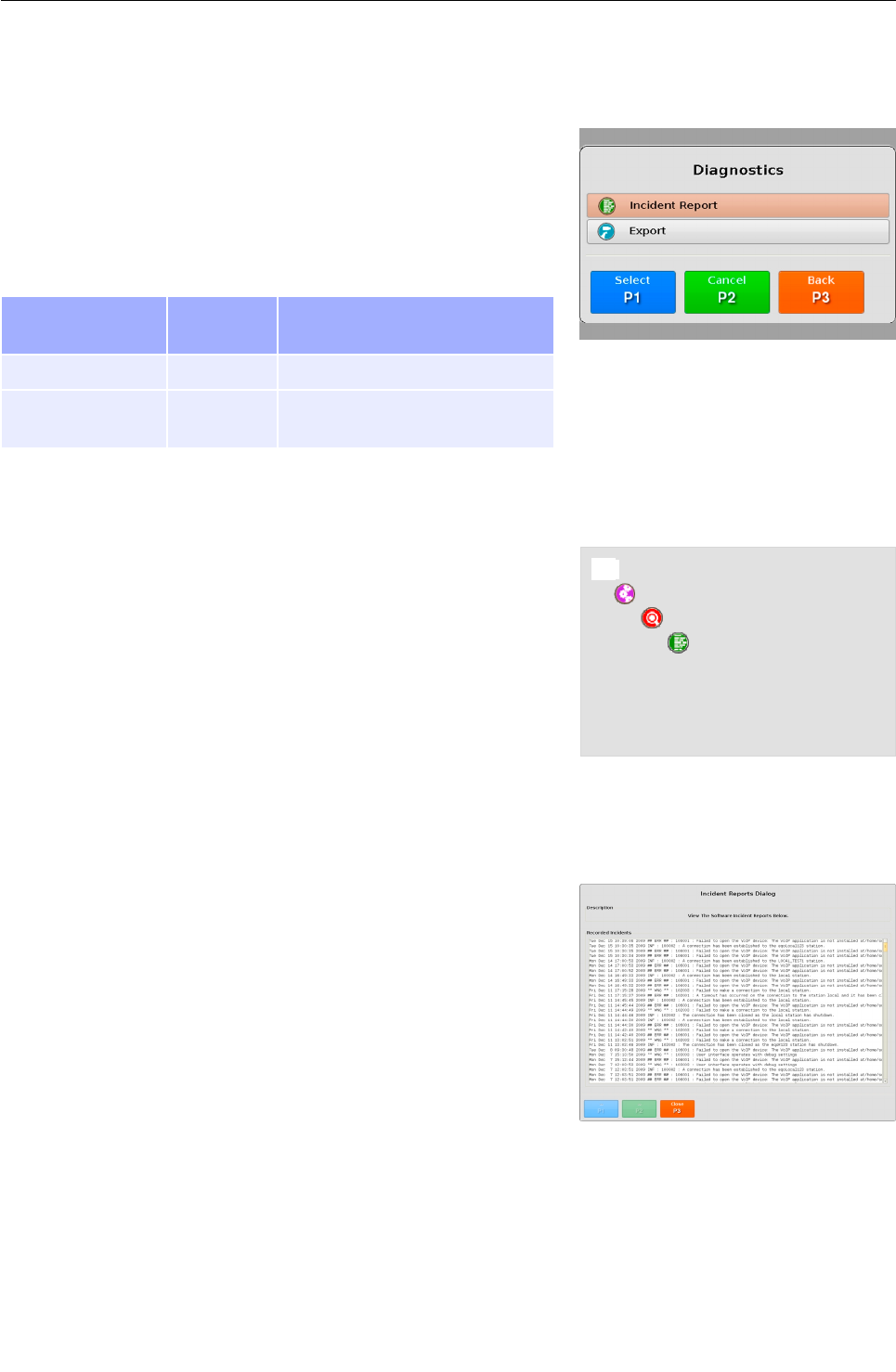
Diagnostics
In case of a malfunction of eqo the diagnostics functions help you
as an operator to localise or narrow down the problem.
Depending on the user login the menu items can differ, some items
can be invisible. Navigate between the menu items using the navig-
ator and select the desired menu item by pressing T. The fol-
lowing table explains accessible menu items.
Menu item Visible for
user role
Description
Incident Report 135, 246 View incident report
Export 135, 246,
2110, 3110
View or export the set up dia-
gnostics report
Incident Report
The “Incident Report” gathers information about the the status of
eqo and records every malfunction of the system.
The navigation tree in Fig. 41 shows a quick overview how to navig-
ate to the “Incident Report” dialog.
Press the 8 key to open the main menu (see Fig. 22).
Navigate to the “System Control” menu item using the navigator
control on the keyboard ( 13) and select it by pressing T.
In the “System Control” menu navigate to the “Diagnostics”
menu item and select it by pressing T. The “Diagnostics”
menu is displayed.
In the “Diagnostics” menu navigate to the “Incident Report”
menu item and select it by pressing T. The “Incident Re-
port” dialog is displayed (see Fig. 42).
Use the navigator control on your keyboard to scroll down in the
incident report. Press V to close and jump back to the “Dia-
gnostics” menu.
95591706 11/02/2010 © smiths detection proprietary information
Fig. 42: “Incident Report” dialog
Fig. 40: Menu: “Diagnostics”
Fig. 41: Navigation tree to the “Incident
Reports” dialog
8 Main Menu
$ System Control
$ Diagnostics
$ Incident Report
$ Incident Report Dialog
32
Product description
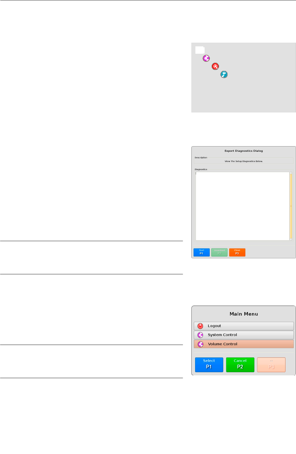
Export the set up diagnostics
The “Setup Diagnostics Report” gathers the configuration informa-
tion of your eqo system. These have been created during the setup
of the system.
Depending on your access rights you are allowed to view only or
download the “Setup Diagnostics Report”.
The navigation tree in Fig. 43 shows a quick overview how to navig-
ate to the “Setup Diagnostics Report” dialog.
Press the 8 key to open the main menu (see Fig. 22).
Navigate to the “System Control” menu item using the navigator
control on the keyboard ( 13) and select it by pressing T.
In the “System Control” menu navigate to the “Diagnostics”
menu item and select it by pressing T. The “Diagnostics”
menu is displayed.
In the “Diagnostics” menu navigate to the “Export” menu item
and select it by pressing T. The “Export Diagnostics” dialog
is displayed (see Fig. 44).
Press T to create the “Setup Diagnostics Report” and use
the navigator control on your keyboard to scroll down in the “Ex-
port Diagnostics Report”.
Important!
The export functionality is only available at the local sta-
tion!
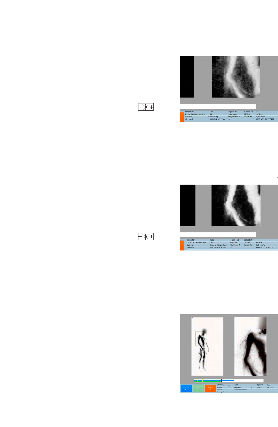
Volume control
The volume control is the master control for the VoIP system. It al-
lows you to adjust the level of the speaker and microphone of the
audio connection established between local operator and remote
operators.
Important!
The headsets of the audio system have their own indi-
vidual volume control.
If the audio system uses radio communication only, then these set-
tings don't impact the volume control. Depending on the user login
the menu items can differ, some items can be invisible. Navigate
between the menu items using the navigator and select the desired
menu item by pressing T.
95591706 11/02/2010 © smiths detection proprietary information
Fig. 44: “Export Diagnostics” dialog
Fig. 43: Navigation tree to the “Setup
Diagnostics Report” dialog
8 Main Menu
$ System Control
$ Diagnostics
$ Export
$ Export Diagnostics Dialog
Fig. 45: Main menu – Volume Control
33

Product description
Press the 8 key to open the main menu (see Fig. 22).
Navigate to the “Volume Control” menu item using the navigator
control on the keyboard ( 13).
Select the “Volume Control” menu item by pressing T. The
“Volume Control” screen (see Fig. 46) is displayed.
Fig. 46 shows the “Volume Control” dialog.
Important!
Move between adjacent items in screen menus or win-
dows by directing the navigator up or down.
If you direct the navigator to the right or to the left, you
adjust the speaker and microphone levels.
Press T to apply the changes and exit to the main screen or
V to discard your changes and close the “Volume Control”
dialog.
95591706 11/02/2010 © smiths detection proprietary information
Fig. 46: “Volume Control” dialog
34
Product description
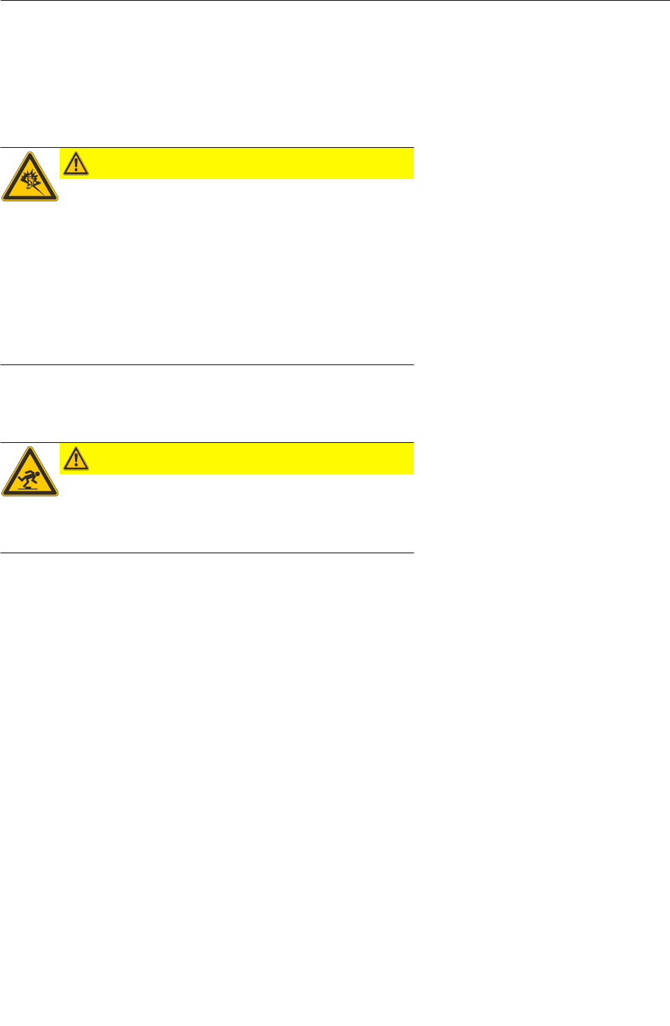
Image enhancement features
Brightness
Pressing the ` key, switches between brightness and contrast ad-
justment. Fig. 48 shows the title bar with activated brightness ad-
justment.
Use the ` key to switch to brightness adjustment if necessary.
Press the „Contrast / Brightness Adjustment“ key to in-
crease/decrease the brightness of the displayed image in steps of 8
from -64 to +64.
Contrast
Pressing the ` key switches between contrast and brightness
adjustment. Fig. 47 shows the title bar with activated contrast ad-
justment.
Use the ` key to switch to contrast adjustment if necessary.
Press the „Contrast / Brightness Adjustment“ key to in-
crease/decrease the contrast in steps of 1 from -28 to +7.
Invert
When the key is pressed the image of the screen inverts as
shown in Fig. 49.
95591706 11/02/2010 © smiths detection proprietary information 35
Fig. 49: Image display in invert mode
Fig. 48: Tile bar – Image enhancement:
Contrast
Fig. 47: Title bar – Image enhancement:
Brightness

Product description
Zoom
One frame shows the normal (non-zoomed) image, and the other
the zoomed image. The zoom factor can be increased / decreased
from 2x to 4x to 8x, by pressing Q.
A blue box appears on the standard frame, and it may be moved
using the blue navigator key. This blue box indicates the region
which is to be zoomed in on.
95591706 11/02/2010 © smiths detection proprietary information
36
Fig. 50: Image display with activated zoom
Safety instructions
Safety instructions
Safety instructions for start up
CAUTION
Risk of hearing damage!
Excessive sound volume settings or “sound-spikes” on
the audio headsets could lead to temporary or perman-
ent hearing loss.
When adjusting the volume level of your headset in-
crease the sound level in small steps. Adhere the safety
instructions of the annexed documentation “Plantronics
Savi Office W0100 – Professional Wireless Headset Sys-
tem (W01 Base + WH100 Headset) with Optional HL10
Lifter – User Guide“!
Safety instructions for operation
CAUTION
Risk of falling!
When walking through the arch there is a potential trip
hazard. Persons to be scanned should be made aware of
this!
95591706 11/02/2010 © smiths detection proprietary information 37

Safety instructions
95591706 11/02/2010 © smiths detection proprietary information
38
Start up
Start up
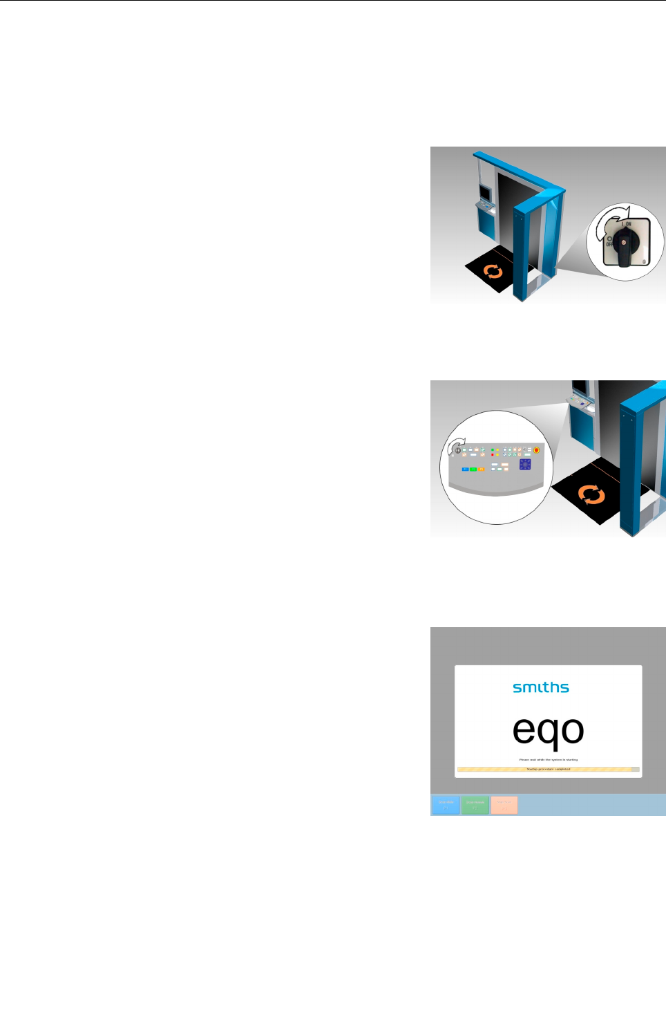
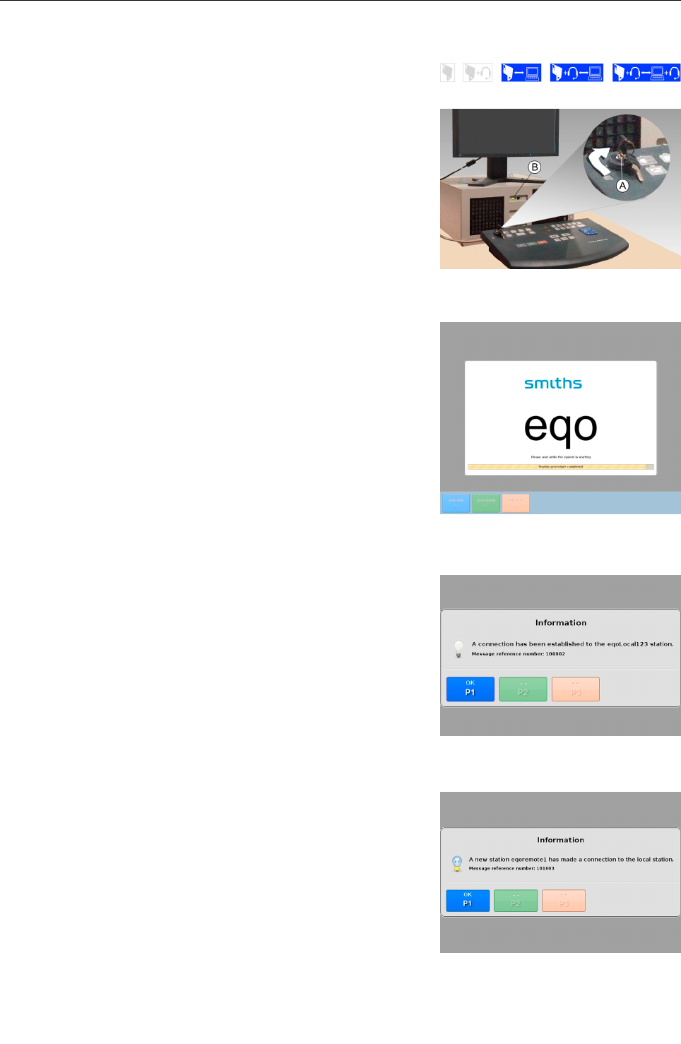
Switching on the local station
Turn the main switch of the eqo system clockwise into the ON
position (see Fig. 51). The unit is now ready to switch-on.
Turn the key switch of the eqo system clockwise (into position II)
in order to switch on the unit (see Fig. 52). The key switch will
backslide automatically to position I.
After the initial boot sequence, a splash screen will appear (see
Fig. 53) on the monitor, which will clear after approximately five
minutes when the system has started. During that time eqo is per-
forming several start-up activities. The text on the progress bar re-
flects the system start-up activities which are:
- Connecting to hardware
- Hardware performing start up procedure
- Hardware performing start-up
- Hardware performing background collection
- Start up is completed
95591706 11/02/2010 © smiths detection proprietary information
Fig. 51: Main switch
Fig. 53: Splash screen
39
Fig. 52: Key switch of the local operator
keyboard
Start up
Logon to the local station
The splash screen is followed by the login screen (see Fig. 54).
Enter your login data by using the function keys and the nav-
igator (see Fig. 55).
Important!
Inside an input field the lower-case numbers and letters
[1 abc] ... [0 _.] written above each function key are act-
ive. This gives the operator the ability to enter letters
and numbers. The numbers are used by default. To
switch between the entry of letters and numbers press
/ Q.
You can delete wrong text entries by moving the cursor
to the left using the navigator.
In the event of a failed log-in a “Login failed” message is displayed
(see Fig. 27 and Fig. 28.on page 26). In this case press T on the
keyboard to return to the log-in screen (see Fig. 54).
After a successful login, the main screen is displayed (see Fig. 56).
Important!
One should wait 5 minutes before performing scans, as
there is a “background collection” task initiated, which
needs to be completed, to enable the system to prepare
to capture images correctly. The scanning area should
be kept clear during this time, and at all times other
than when a scan is in progress.
95591706 11/02/2010 © smiths detection proprietary information
Fig. 54: Login screen
40
Fig. 55: Function keys and navigator
Fig. 56: Local operator station's main screen
Start up
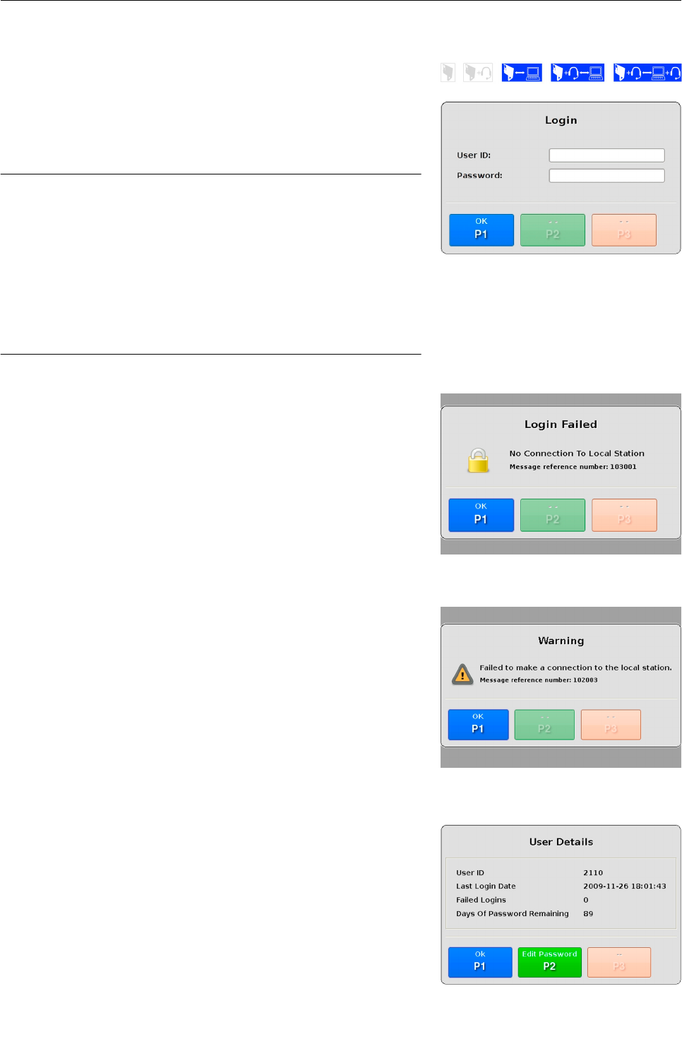
Switching on the remote station
Turn the key switch of the remote station clockwise (into pos-
ition II) in order to switch on the unit (see Fig. 57). The key
switch will backslide automatically to position I and the green
LED lights up.
After the initial boot sequence, a splash screen will appear (see
Fig. 61) on the monitor, which will clear after approximately five
minutes when the system has started. During that time the remote
station is performing several start-up activities. The text on the
progress bar reflects the system start-up activities.
One of these start up activities is to search for a local station to
connect to. If the remote station locates the local station it estab-
lishes a connection and a message box is displayed, that a connec-
tion to an eqo local station has been established (see Fig. 59).
Acknowledge this message by pressing T.
At the same time a message will appear at local operator station
which informs the local operator that a remote station has made a
connection to the local station.
Acknowledge this message by pressing T.
95591706 11/02/2010 © smiths detection proprietary information 41
Fig. 57: Key switch of the remote station
Fig. 60: Connection established with remote
station
Fig. 59: Connection established to local station
Fig. 58: Splash screen
Start up
Logon to the remote station
The splash screen is followed by the login screen (see Fig. 61).
Enter your login data by using the function keys ( 13).
Important!
Inside an input field the lower-case numbers and letters
[1 abc] ... [0 _.] written above each function key are act-
ive. This gives the remote operator the ability to enter
letters and numbers. The numbers are used by default.
To switch between the entry of letters and numbers
press Q .
You can delete wrong text entries by moving the cursor
to the left using the navigator.
A remote login will fail if there is no connection to a local station or
if a remote operator has already logged in, who is of an equivalent
gender. For example if a male remote operator is logged in, then a
login at the other remote station by a male operator will fail.
In the event of a failed log-in, Fig. 61 is displayed. Press T
on the keyboard to return to the log-in screen (see Fig. 61).
In the event that the remote station can't find a local station a mes-
sage box is displayed that the remote station failed to make a con-
nection to the local station (see Fig. 62).
Acknowledge this message by pressing T.
After a successful login, the login information dialog will appear.
This contains details about the last login date, the number of failed
logins and the number of days remaining on the password. Press-
ing U the remote operator gets the ability to change the pass-
word ( 26).
Acknowledge this message by pressing T.
95591706 11/02/2010 © smiths detection proprietary information
42
Fig. 61: Login screen
Fig. 63: Login information dialog
Fig. 62: Failed to connect to a local station
Fig. 61: “Login Failed” screen

Start up
After acknowledging the login message, the main screen will ap-
pear (see Fig. 64).
95591706 11/02/2010 © smiths detection proprietary information 43
Fig. 64: Remote station's main screen

Start up
Audio communication
In combination with the eqo system three different audio commu-
nication configurations are possible.
No audio solution provided
Wireless audio base at local station only
Wireless audio base at local and remote station
In the following the different audio communication configurations
will be described in detail:
No audio solution provided
If no audio solution has been provided, it may be the case that you
are already using a communication solution or your concept of op-
eration does not require and a communication solution.
Audio base at the local station only
A wireless audio base is located at the local station of the eqo sys-
tem. This facilitates up to four operators to conference over an au-
dio channel to one another.
To protect the subject's privacy the system is configured with local
and remote stations. The remote stations are physically separated
from the local station. The remote operator subscribes his headset
to the audio base connected to the local station.
Important!
Depending on the proximity of the local and remote sta-
tions and customer requirements a second base may be
mandatory.
Audio base at local and remote station
One wireless audio base is located at the local station, a second
one at the remote station of your eqo system.
Up to four local operators subscribe their headsets to the wireless
audio base connected to the local station, the remote operator sub-
scribes his headset to the base which is connected to the remote
station.
The communication link between local and remote operator station
is established via a network connection between local and remote
station using Voice over IP (VoIP). This communication link is con-
trolled by the eqo system and only established as long as a scan-
ning process is is active.
95591706 11/02/2010 © smiths detection proprietary information
44
Start up
Important!
Prior to using the audio hardware, read the annexed
documentation ”Plantronics Savi Office W0100 – Profes-
sional Wireless Headset System (W01 Base + WH100
Headset) with Optional HL10 Lifter – User Guide“!
Subscribing a master headset to the local station audio base sta-
tion
The primary local operator subscribes his headset as master. Oth-
er operators are linked in via a conferencing facility ( 45, Confer-
ence in additional headsets). This local wireless link is independent
of eqo and remains in place until terminated by one of the operat-
ors.
Step 1:
Double press the subscribe button on the base.
The subscribe indicator will flash red and green.
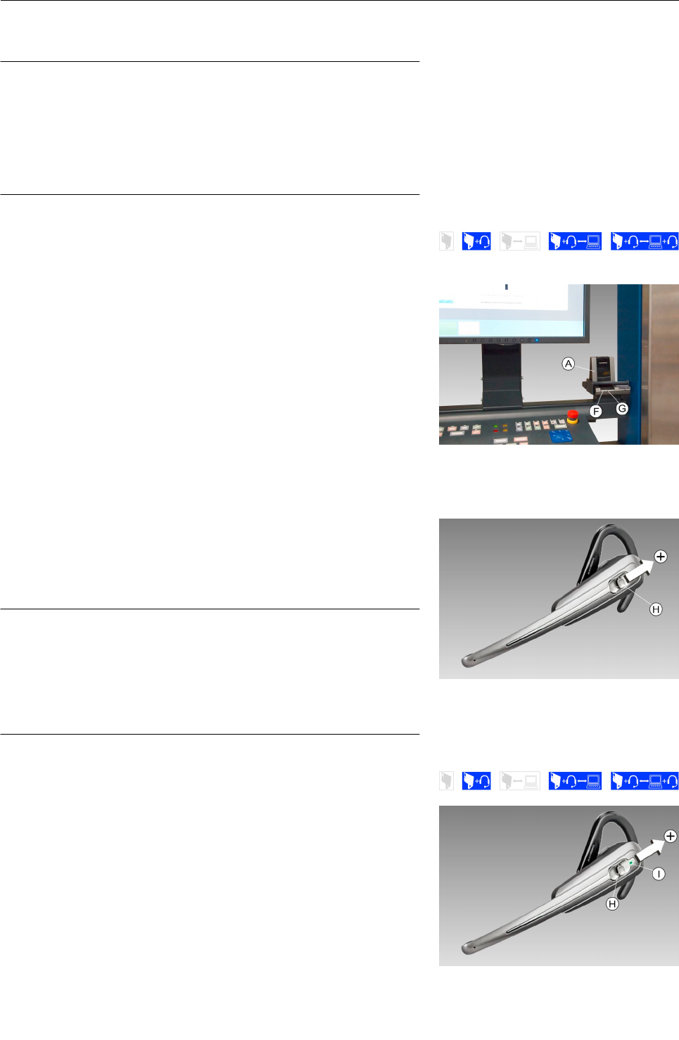
Step 2:
Press the call control button (volume up button) on the headset
up for three seconds. When the subscribe indicator turns
solid green at the base, the subscription process is completed.
Important!
If the subscription process times out after two minutes
or if the subscription process fails, the subscription light
will become solid red for four seconds and then return
to its previous state. If this occurs, try to re-subscribe
the headset again.
Conference in additional headsets
Up to four headsets can be subscribed to the wireless audio base
for conferencing. Follow the following steps to conference in a
headset.
Step 1:
Place the headset into over-the-air subscription mode by push-
ing the headset call control button (volume up button) up for
three seconds.
The indicator light of the headset becomes solid green.
95591706 11/02/2010 © smiths detection proprietary information 45
Fig. 65: Wireless audio base at the local station
Fig. 67: Headset
Fig. 66: Headset
Start up
Step 2:
Short press (less than one second) the subscription button on
the wireless audio base .
The subscription indicator will flash yellow and green. When
it turns to solid yellow, you will hear a tone in the master head-
set. This indicates to the master headset, that a headset wants
to join the conference.
Step 3:
Press the call control button on master headset within five
seconds to accept the conferencing request (see Fig. 67).
The headset has joined the conference.
Important!
If the call control button on the master headset isn't
pressed within five seconds the guest's request to con-
ference is rejected and they will hear an error tone in
their headset.
Adjusting the headset hearing volume
CAUTION
Risk of hearing damage!
Excessive sound volume settings or “sound-spikes” on
the audio headsets could lead to temporary or perman-
ent hearing loss.
When adjusting the volume level of your headset in-
crease the sound level in small steps. Adhere the safety
instructions of the annexed documentation “Plantronics
Savi Office W0100 – Professional Wireless Headset Sys-
tem (W01 Base + WH100 Headset) with Optional HL10
Lifter – User Guide“!
Push the call control button up/down to adjust the volume of
the headset. Tones indicate the volume level.
Important!
The headset transmit volume is set over the menu op-
tion by the PC ( 33).
95591706 11/02/2010 © smiths detection proprietary information
46
Fig. 68: Wireless audio base at the local station
Fig. 69: Adjustment of the headset volume

Start up
Terminate a conference link
Press the call control button on a guests headset to leave the
conference.
A single tone in the master headset indicates that a guest has
left the conference.
Important!
If you want to terminate the conference press the call
control button on the master headset.
Subscribing headset a master to the remote station's audio base
Follow the steps 1-2 on the page 45 (Subscribing a master
headset to the local station audio base station) to subscribe a
headset as master to the remote station's wireless audio base.
95591706 11/02/2010 © smiths detection proprietary information 47
Fig. 70: Headset

Start up
95591706 11/02/2010 © smiths detection proprietary information
48
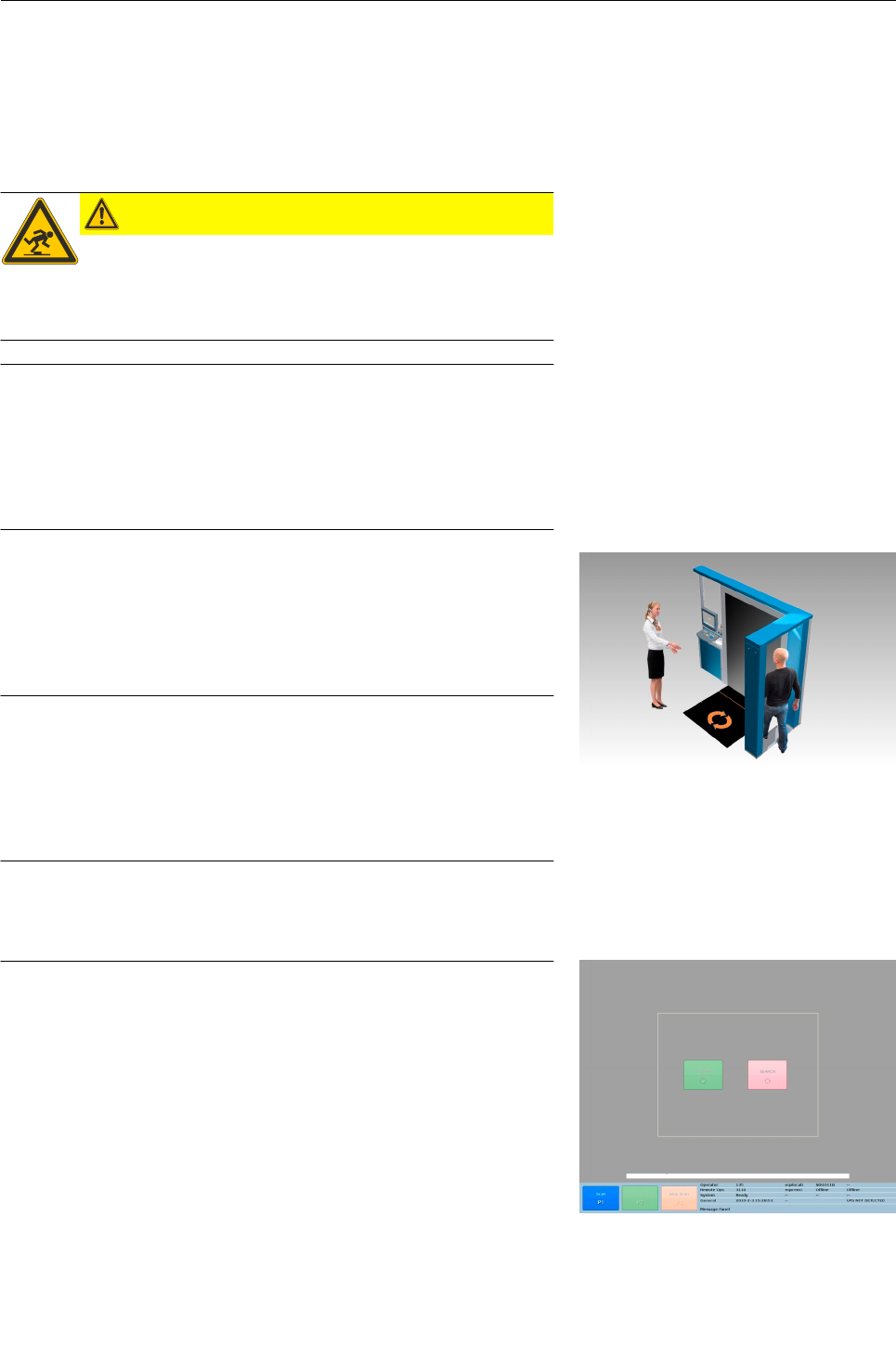
Operation
Operation
Conducting the person into the scanning area
CAUTION
Risk of falling!
When walking through the arch there is a potential trip
hazard. Persons to be scanned should be made aware of
this!
Important!
In the following one screening process will be explained.
Please remember that this is only one possible concept
of operation (CONOPS) for the eqo system. Depending
on your requirements your CONOPS can be different
from the described CONOPS below.
Direct the person to be scanned through the arch, into the scan-
ning area.
The optimum position for the person is marked by a symbol on
the floor mat. The person should stand in front of the flat scan-
ning panel with arms down, facing the local operator.
Important!
Remember that the minimum distance between the per-
son to be scanned and the flat scanning panel of the
eqo system is 30 cm. The person should stand at the
centre of the operational area as indicated by the sym-
bol on the floor.
Screening process
Important!
When the eqo system is configured with a remote sta-
tion, starting the screening process is only possible as
long as the remote operator station is in “Ready”-state.
When the remote operator is inside a menu, and the loc-
al operator presses T, a message at the local sta-
tion's screen is displayed indicating that the remote sta-
tion is busy.
Press T at the local station to start the screening process.
The image capturing begins.
95591706 11/02/2010 © smiths detection proprietary information
Fig. 71: Local operator directing a person into
the imaging volume
49
Fig. 72: Local station's main screen when
system configured with remote station
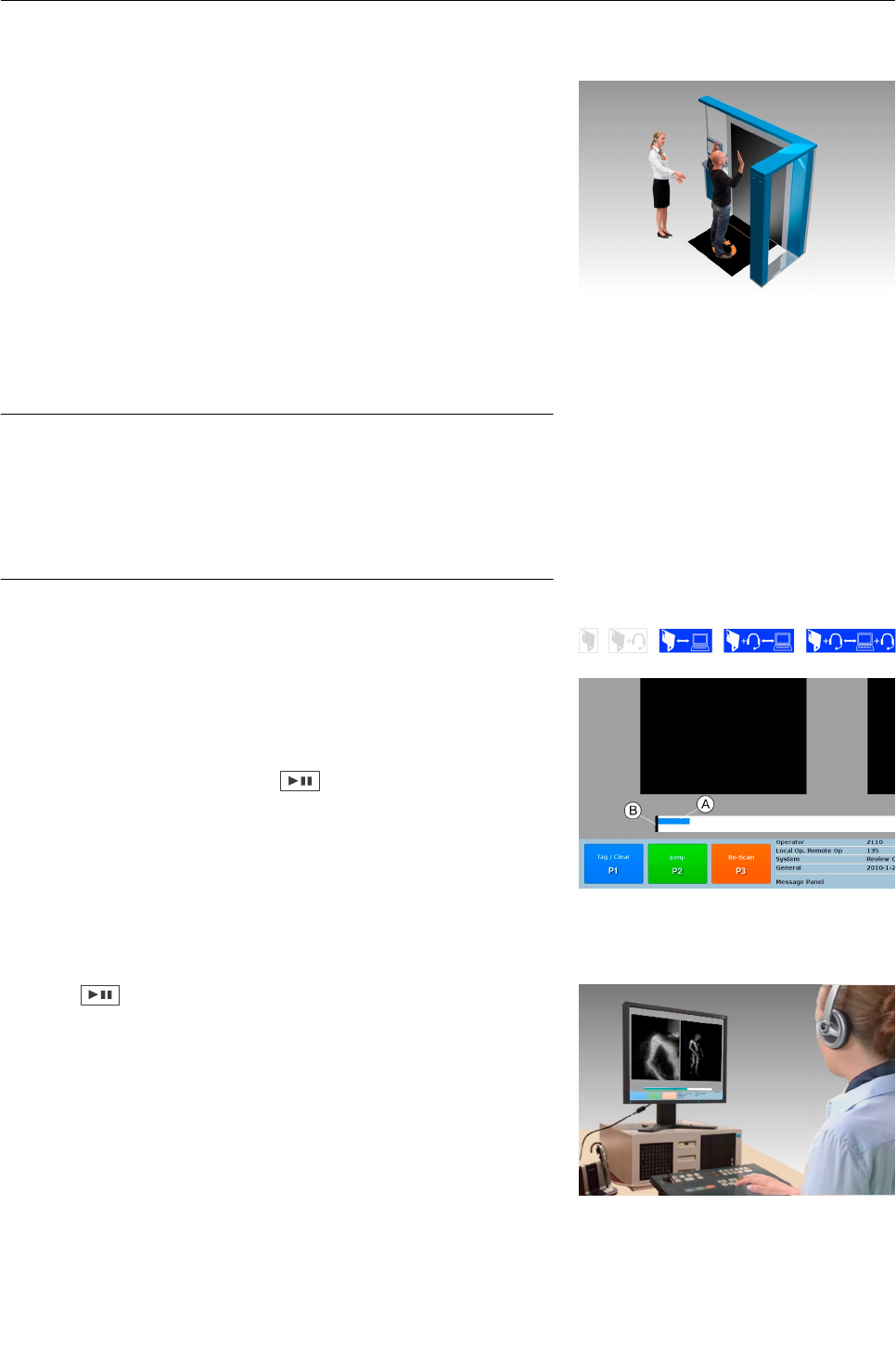
Operation
Instruct the person to turn in slow motion through at least 360
degrees. Before they begin turning, they must raise their arms
up as shown in Fig. 73.
This allows the remote operator, during the screening process
to view also the sides of the arms
Press V in order to stop the image capturing. Image captur-
ing will also stop after the maximum scanning time of 30
seconds has elapsed.
If no anomaly is detected, the person who has been scanned can
then be told that they are free to proceed.
Important!
In the case where an anomaly has been identified, any
site specific standard operating procedure (SOP) should
be followed. For example a targeted pat-down should be
performed as indicated by the position of the anomaly
on the image.
Reviewing the image sequence
To avoid, that the operator misses the beginning of the live image
capture, the scan information is buffered. After starting the scan at
the local station, the blue progress bar indicates the progress of
the live image capture.
The remote operator must press before the image sequence
will begin playback on the remote operator's screen.
The blue bar shows the current position of the LIVE scan. The
green bar shows the amount of the sequence that the operator has
reviewed. The black cursor shows the actual position within the
image sequence the operator is reviewing.
Press at the remote station to start the display of the im-
age sequence.
The remote operator (see Fig. 75) reviews the mm-wave image and
evaluates the image to decide whether the subject is clear or is
suspect. While reviewing the mm-wave image the remote operator
uses the function keys to tag anomalies and to move forwards and
backwards on the timeline through the image data.
95591706 11/02/2010 © smiths detection proprietary information
50
Fig. 75: Remote operator reviewing the image
Fig. 73: Person standing in screening position
Fig. 74: Progress bar
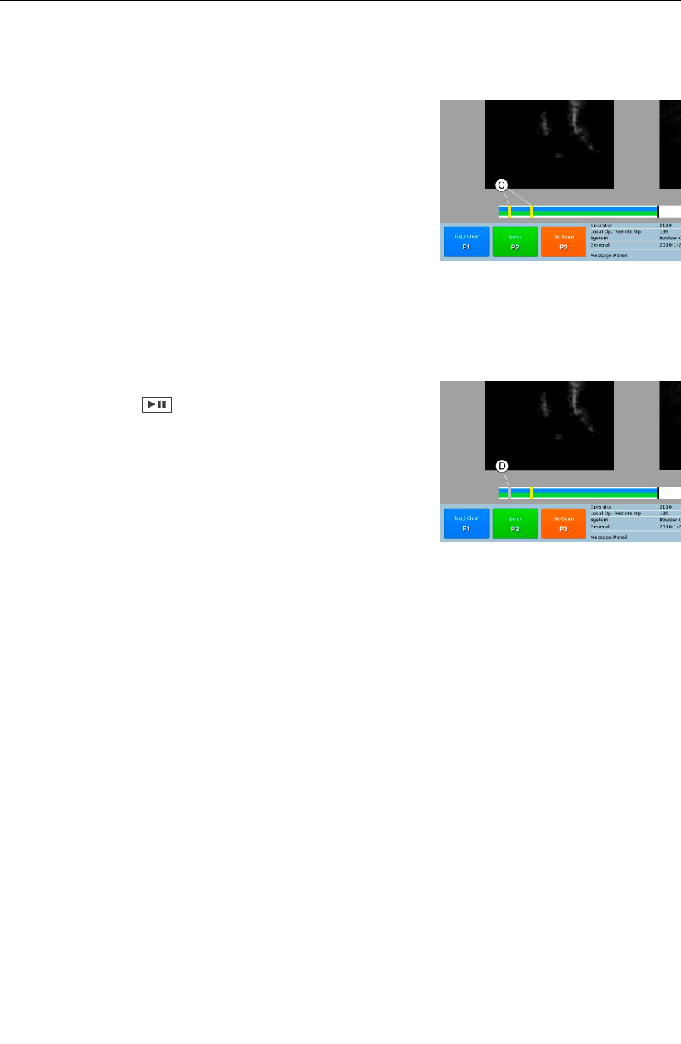
Operation
Tag areas of interest
Pressing T while the image plays allows the operator to mark
areas of interest where potential threats are identified. Yellow
marker positions in the green and blue bar identify these posi-
tions in the image data (see Fig. 76). They can be used to quickly
find these positions in the image data to playback that portion of
the image for further analysis.
Reviewing tags
To review areas of interest, the image playback must be paused,
either by pressing the key during a scan, or after a screening
process has been stopped at the local station.
While the image playback is paused, it is possible to review areas of
interest. Pressing U will skip the tags in sequence, if there
have been any marked and playback the a short image sequence
around the tag.
After reviewing a tag, the operator can clear the tag by pressing the
T key again or jump to the next tag by pressing U. After
clearing a tag, the cleared tag will appear grey on the time line
(see Fig. 77).
Using the control keys ( 13) allows the operator to move the im-
age backwards or forwards in the image sequence and in different
speeds on the time line.
95591706 11/02/2010 © smiths detection proprietary information
Fig. 76: Tags on the timeline
Fig. 77: Cleared tags
51
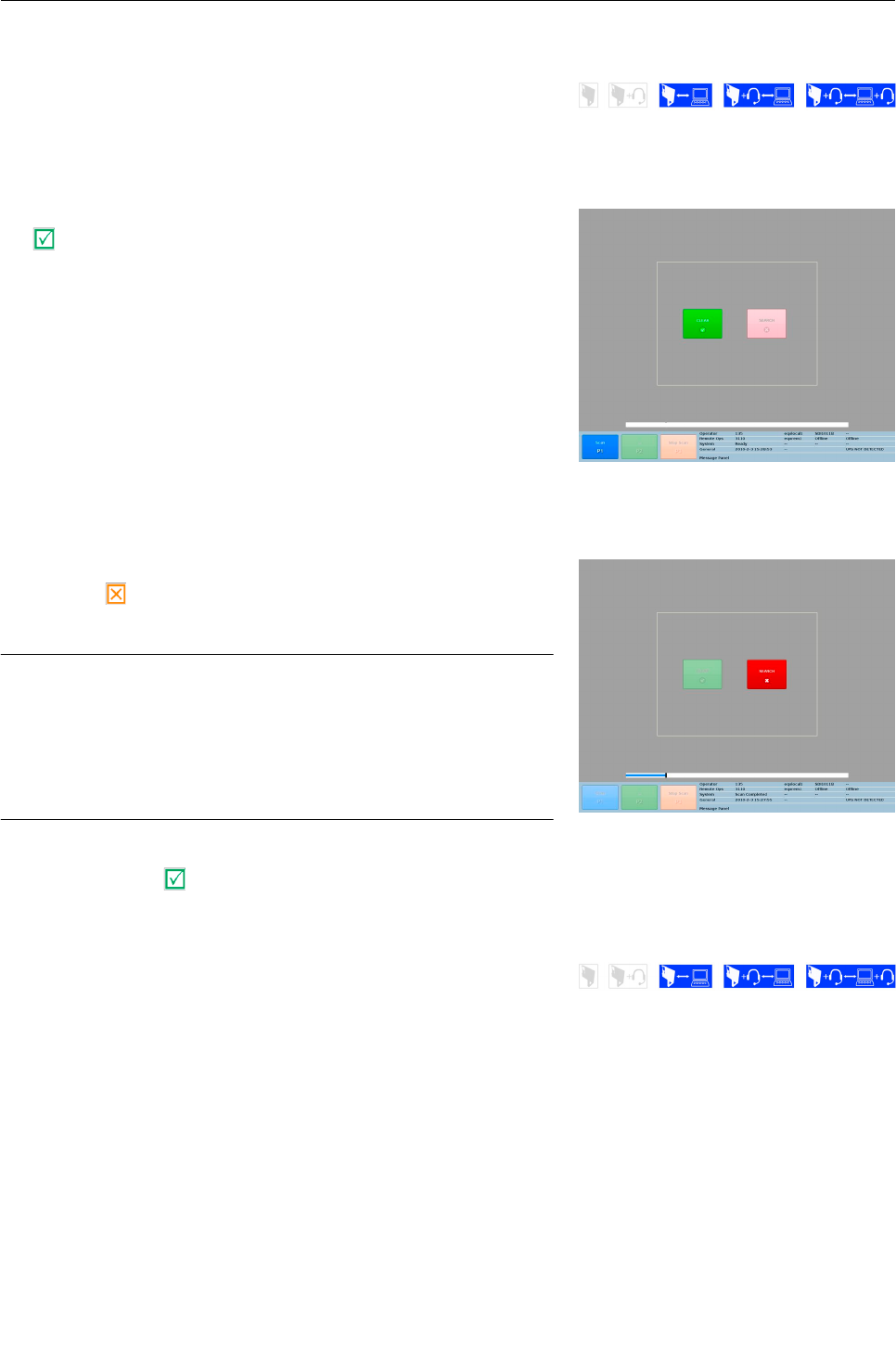
Operation
Evaluation of the image sequence
After reviewing an image sequence the remote operator has to
evaluate the image data.
In case, that no anomaly has been identified, he presses the clear
key on the function key panel ( 16).
At the local station's main screen the clear-button is highlighted,
and the local operator station returns to ready state (see Fig. 78).
In case, that remote operator identifies an anomaly, he presses the
suspect key and communicates the position of the anomaly via
an audio channel to the local operator
Important!
In the case where an anomaly has been identified, any
site specific standard operating procedure (SOP) should
be followed. For example a targeted pat-down should be
performed as indicated by the position of the anomaly
on the image.
After the SOP has been accomplished the remote operator has to
press the clear key to get the local station back to the “Ready”-
state.
Initiate a Re-Scan
In case, that the image sequence has been to short or the quality of
the collected image sequence is insufficient the remote operator
has the possibility to initiate a Re-Scan by pressing V.
The Re-Scan is available anytime during the remote reviewing ses-
sion. If the re-scan is pressed it has the effect of clearing the scan
on the local station but it does not report a decision i.e. “CLEAR” or
“SEARCH”.
The Re-Scan has the effect of a new scan, but the passenger count
is not incremented.
95591706 11/02/2010 © smiths detection proprietary information
52
Fig. 78: Local station in ready state
Fig. 79: Local station's main screen - “search”
button active

Operation
Pressing V will clear the timeline and the “Clear/Search” but-
tons at the local station if activated. The local station's status will
change to the “Ready”-state and the T button will enable.
At the remote station the timeline and the image are cleared. The
status of the remote station will change to the “Waiting”-state and
the screening process can now be repeated.
95591706 11/02/2010 © smiths detection proprietary information 53

Operation
95591706 11/02/2010 © smiths detection proprietary information
54
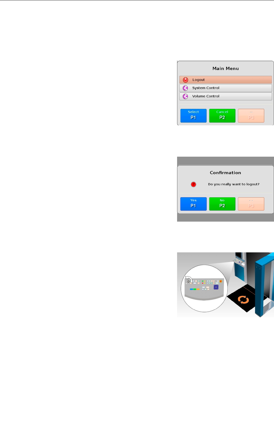
Shut-down
Shut-down
Shut-down the local station
Step 1:
Press 8 and the main menu is displayed (see Fig. 80).
Step 2:
Use the navigator control on the keyboard ( 13) to select the
Logout menu item.
Step 3:
Press T to select logout menu item.
The logout confirmation screen (see Fig. 81) is displayed.
Choosing U will bring you back to the main screen.
Step 4:
Press T to confirm the logout process.
Choosing U will cancel the logout and bring you back to the
main menu (see Fig. 81).
Step 5:
Turn the key switch to the left (into position 0) in order to switch
off the unit (see Fig. 82).
95591706 11/02/2010 © smiths detection proprietary information
Fig. 81: Logout confirmation screen
Fig. 80: Main menu
55
Fig. 82: Key switch of the local operator
keyboard
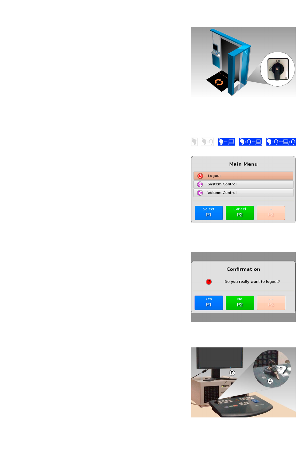
Shut-down
Step 6:
Turn the main switch to the left into position OFF (see Fig. 83).
Shut-down the remote station
Step 1:
Press 8 and the main menu is displayed (see Fig. 84).
Step 2:
Use the navigator control on the keyboard ( 13) to select the
Logout menu item.
Step 3:
Press T to select logout menu item.
The logout confirmation screen (see Fig. 85) is displayed.
Choosing U will bring you back to the main screen.
Step 4:
Press T to confirm the logout process.
Choosing U will cancel the logout and bring you back to the
main menu (see Fig. 85).
Step 5:
Turn the key switch of the remote station counter to the left
(into position 0) in order to switch off the unit (see Fig. 86).
95591706 11/02/2010 © smiths detection proprietary information
Fig. 83: Main switch
56
Fig. 86: Key switch of the remote station
Fig. 85: Logout confirmation screen
Fig. 84: Main menu
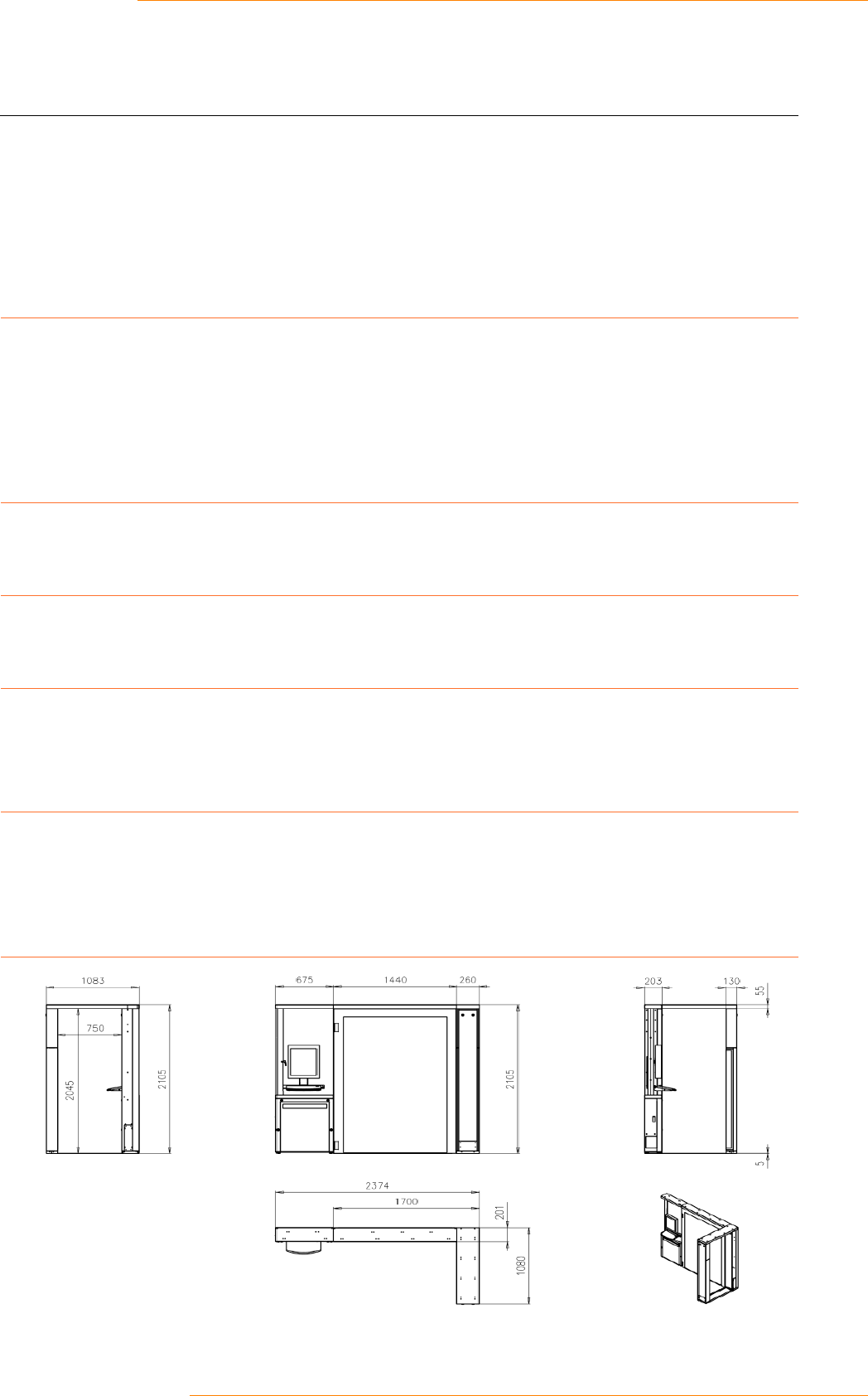
Technical data
Technical data
Local Station
Electrical data
Power Supply 100-240 VAC, N, PE
Power Consumption 1.36 kVA
Frequency 50 - 60 Hz
Fuse 2 x 10 A
Sound Pressure Level
Sound Pressure Level < 55 dBA
Weight
Weight < 400 kg
Temperatures
Storage Temperature -20° C to + 70° C
Operating Temperature 0° C to +40° C
Environment
Relative Humidity (non-
condensing)
10% to 98%
Altitude 2 km max
Dimensions
95591706 11/02/2010 © smiths detection proprietary information 57

Technical data
Remote Station
Electrical data
Power Supply 90-264 V AC, N, PE
Power Consumption 300 W
Frequency
Sound Pressure Level
Sound Pressure Level < 55 dB
Weight
Weight < 20 kg
Temperatures
Storage Temperature -20° C to + 70° C
Operating Temperature +5° C to +40° C
Environment
Relative Humidity (non-
condensing)
10% to 90%
Altitude 2 km max
Dimensions
Depth 438 mm
Width 177 mm
Height 424 mm
95591706 11/02/2010 © smiths detection proprietary information
58

Annex A
Annex A
Daily Test Procedure
After starting eqo each morning, the operator is advised to perform
a test card scan. This is done using a specifically designed test card
(see Fig. 86). The card is manufactured from a plastic material
which is transparent to millimetre waves. Metal strips of different
widths are attached to the surface of the card. The number next to
each section signifies the width of each strip in that section and the
gap between adjacent metal strips.
During the test the operator holds the card vertically in front of the
system (i.e. in the orientation shown in Fig. 86), in the centre of the
scan volume (this is identified by the centre of the symbol on the
floor mat), at a height of approx. 1.5 m from the floor to the top of
the test card.
It is expected that at the centre of the scan volume, a properly set-
up system will be able to resolve lines (horizontal or vertical) of
6mm width. The results of the test will be different depending on
the distance from the panel and the location in the scanned
volume. Moving the test card closer to the panel should result in
the resolution of lines down to 4mm.
Important!
The card may need to be rotated in the vertical plane
(max. 10 degrees) to achieve optimum results.
The test procedure is as follows:
Start the system according to the procedure outlined in the op-
erator manual.
Allow the system to run for a minimum of 5 minutes after log on
- make sure there are no objects in the scan volume during this
time.
Rotate or tilt the card to achieve best image, as described
above.
Review the image after the test using and keys.
Make sure the number of lines on the image corresponds to the
number of lines in the test card.
Watch out for blurring or double lines in the image.
95591706 11/02/2010 © smiths detection proprietary information
Fig. 86: Test card
59
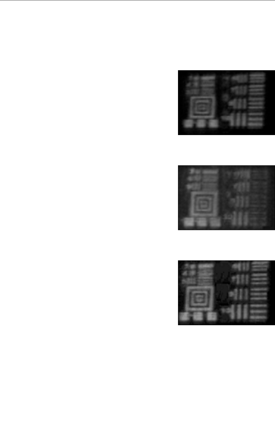
Annex A
In the event of the image result not being acceptable, a system set-
up should be carried out by a suitably trained technician.
Test card example images
Fig. 87 shows an image where the test card is out of focus. The test
card has been placed too far away from the flat scanning panel.
Fig. 88 shows an image where the test card has been placed at an
incorrect angle to the flat scanning panel.
Fig. 89 shows an image where the test card has been positioned
correctly.
95591706 11/02/2010 © smiths detection proprietary information
Fig. 87: Image with test card too far away
Fig. 88: Image with test card at incorrect angle
Fig. 89: Image with test card positioned
correctly
60

Annex A
Fig. 90 shows an image where the test card has been placed closer
to the flat scanning panel.
95591706 11/02/2010 © smiths detection proprietary information
Fig. 90: Image with test card placed closer
61

Annex A
95591706 11/02/2010 © smiths detection proprietary information
62

Annex B
Annex B
Document Order number
Declaration of Conformity – CE 1595 95592593
Eizo FlexScan MX190 - User's Manual 95591608
User's Manual – FlexScan S1932 Color LCD
Monitor - Eizo
95592663
Plantronics Savi Office W0100 – Profession-
al Wireless Headset System (W01 Base +
WH100 Headset) with Optional HL10 Lifter –
User Guide
95591849
95591706 11/02/2010 © smiths detection proprietary information 63