Smiths Detection 2039924 Sensa-LINX, Wireless Early Warning System, 2.4 GHz Variant User Manual Operator s manual
Smiths Detection (Watford) Sensa-LINX, Wireless Early Warning System, 2.4 GHz Variant Operator s manual
Contents
- 1. User Manual
- 2. Quick Reference Guide
User Manual

SENSA-LINX
DETECTOR NETWORKING SYSTEM
OPERATIONAL INSTRUCTIONS/USER MANUAL
Prepared by:
Smiths Detection Ltd.
Park Avenue
Bushey
Watford
Hertfordshire
WD23 2BW
U.K.
Part No. 20270-1B
Date of Issue: Pre Issue 2 Draft Release Feb2012
Smiths
Detection
Smiths
Detection
Smiths
Detection
Smiths
Detection
Smiths
Detection
Smiths
Detection
Smiths
Detection
Smiths
Detection
Smiths
Detection
Smiths
Detection
Smiths
Detection
Smiths
Detection
Smiths
Detection
Smiths
Detection
Smiths
Detection
Smiths
Detection
Smiths
Detection
Smiths
Detection
Smiths
Detection
Smiths
Detection
Smiths
Detection
Smiths
Detection
Smiths
Detection
Smiths
Detection
Smiths
Detection

Preliminary Pages
Page i
SENSA-LINX
DETECTOR NETWORKING SYSTEM
OPERATIONAL INSTRUCTIONS/USER MANUAL
APPROVED BY: ………………………………………………………………..
(Technical Authority)
Prepared by:
Smiths Detection Ltd.
Park Avenue
Bushey
Watford
Hertfordshire
WD23 2BW
U.K.
Part No.
20270-1B
Date of Issue:
Pre Issue 2 Draft Release Feb2012
Smiths
Detection
Smiths
Detection
Smiths
Detection
Smiths
Detection
Smiths
Detection
Smiths
Detection
Smiths
Detection
Smiths
Detection
Smiths
Detection
Smiths
Detection
Smiths
Detection
Smiths
Detection
Smiths
Detection
Smiths
Detection
Smiths
Detection
Smiths
Detection
Smiths
Detection
Smiths
Detection
Smiths
Detection
Smiths
Detection
Smiths
Detection
Smiths
Detection
Smiths
Detection
Smiths
Detection
Smiths
Detection
Preliminary Pages
Page ii
This page is intentionally left blank
Preliminary Pages
Page iii
SENSA-LINX
DETECTOR NETWORKING SYSTEM
OPERATORS’ MANUAL
TABLE OF CONTENTS
FOREWORD .................................................................................................................................. vii
FCC COMPLIANCE ........................................................................................................................ ix
SAFETY SUMMARY ........................................................................................................................ x
WARNINGS & CAUTIONS ............................................................................................................... x
WARNINGS ....................................................................................................................................... x
CAUTIONS ..................................................................................................................................... xiii
REVISION RECORD .....................................................................................................................xvii
CHAPTER 1 INTRODUCTION ......................................................................................................... 1
1.1 Scope of this manual ......................................................................................................... 1
1.2 System Overview ............................................................................................................... 1
1.3 Glossary ............................................................................................................................ 2
1.4 Equipment Overview ......................................................................................................... 2
1.4.1 Command & Control (C2) System ..................................................................................... 2
1.4.2 Base Station Node/Sensor Node ....................................................................................... 4
1.4.3 Sensor Node (Radio Modem) Variants .............................................................................. 5
1.5 Ancillaries .......................................................................................................................... 6
1.5.1 Packaging.......................................................................................................................... 6
1.5.2 Consumables .................................................................................................................... 6
1.5.3 Accessories ....................................................................................................................... 6
1.6 Documentation ................................................................................................................ 13
1.7 Power Options ................................................................................................................. 13
1.7.1 C2 Laptop PC .................................................................................................................. 13
1.7.2 Sensor/Base Station Node .............................................................................................. 13
1.8 Operating Characteristics ................................................................................................ 14
1.8.1 Environmental ................................................................................................................. 14
CHAPTER 2 OPERATING INFORMATION .................................................................................... 15
2.1 Equipments Controls and Indicators ................................................................................ 15
2.1.1 Laptop PC – Controls and Features................................................................................. 15
2.1.2 Sensor Node (Radio Modem) .......................................................................................... 16
2.1.3 Sensor Node Initial Configuration .................................................................................... 16
2.1.4 Sensor Node (Radio Modem) User Interface ................................................................... 17
2.2 ‘Pull the dot’ Fasteners .................................................................................................... 18
2.3 Sensa-LINX Network Set Up & Operation........................................................................ 19
2.3.1 Unpacking and Initial Checks........................................................................................... 19
2.3.2 Base Station Node Set Up ............................................................................................... 22
2.3.3 Sensor Node Set Up ........................................................................................................ 26
2.4 Alarms ............................................................................................................................. 29
2.5 Loss of communications. ................................................................................................. 30
2.6 Saving Network Settings .................................................................................................. 30
2.7 Shut Down ....................................................................................................................... 30
2.7.1 C2 Shut Down ................................................................................................................. 30
2.7.2 Equipment Shut Down ..................................................................................................... 30
2.8 Putting Sensa-LINX Equipment into Storage ................................................................... 31
Preliminary Pages
Page iv
CHAPTER 3 TECHNICAL DESCRIPTION ..................................................................................... 33
3.1 User Accounts on the C2 Laptop or Other Computers ..................................................... 33
3.2 Positioning factors for the Base Station Node .................................................................. 34
3.3 Positioning factors for the Sensor Node ........................................................................... 34
3.4 Detailed C2 Description ................................................................................................... 35
3.4.1 GUI Layout ...................................................................................................................... 35
3.4.2 Menus .............................................................................................................................. 37
3.4.3 Status bar ........................................................................................................................ 43
3.4.4 Sensor Node List ............................................................................................................. 45
3.4.5 Maps ................................................................................................................................ 47
3.4.6 Detail Panels ................................................................................................................... 49
3.4.7 Alarms Log window .......................................................................................................... 58
3.4.8 Warnings window ............................................................................................................. 60
3.4.9 Events window ................................................................................................................. 61
CHAP TER 4 INS TALLATION INFORMATION ............................................................................... 63
4.1 Sensa-LINX Software Install and Uninstall ....................................................................... 63
4.2 Sensa-LINX C2 and NCT Installation ............................................................................... 63
4.3 Uninstalling Sensa-LINX C2 and NCT ............................................................................. 64
4.4 Map Installation ................................................................................................................ 65
4.5 Uninstalling Maps ............................................................................................................ 65
CHAP TER 5 MAINTENANCE INFORMATION an d INSTRUCTIONS ............................................ 67
5.1 General ............................................................................................................................ 67
5.2 Preventive Maintenance .................................................................................................. 67
5.2.1 General Cleaning ............................................................................................................. 68
5.3 Corrective Maintenance ................................................................................................... 68
5.3.1 Equipment Decontamination ............................................................................................ 69
5.3.2 Post Decontamination Checks ......................................................................................... 71
5.3.3 Replace Sensor Node Batteries or Battery Cassette ........................................................ 71
5.3.4 Replace Sensor Node Antenna ........................................................................................ 73
5.3.5 Replace Inoperative Sensa-LINX Equipment ................................................................... 73
5.4 Fault Analysis .................................................................................................................. 74
5.4.1 Fault Diagnosis ................................................................................................................ 74
5.4.2 Fault Messages ............................................................................................................... 77
CHAPTER 6 SPARES INFORMATION .......................................................................................... 79
6.1 General ............................................................................................................................ 79
APPENDIX A ................................................................................................................................ A-1
Network Configuration Tool (NCT) User Instructions .............................................................. A-5
TABLE OF FIGURES
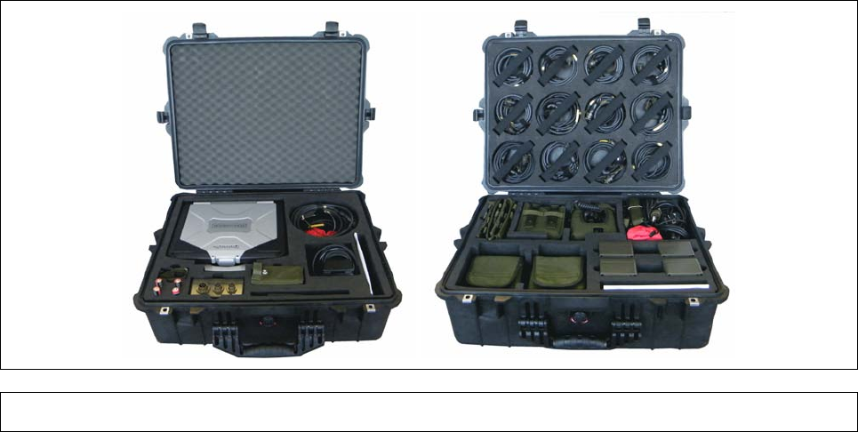
Figure 1 Base Station Node and Sensor Node Pelican Cases ..................................................... 1
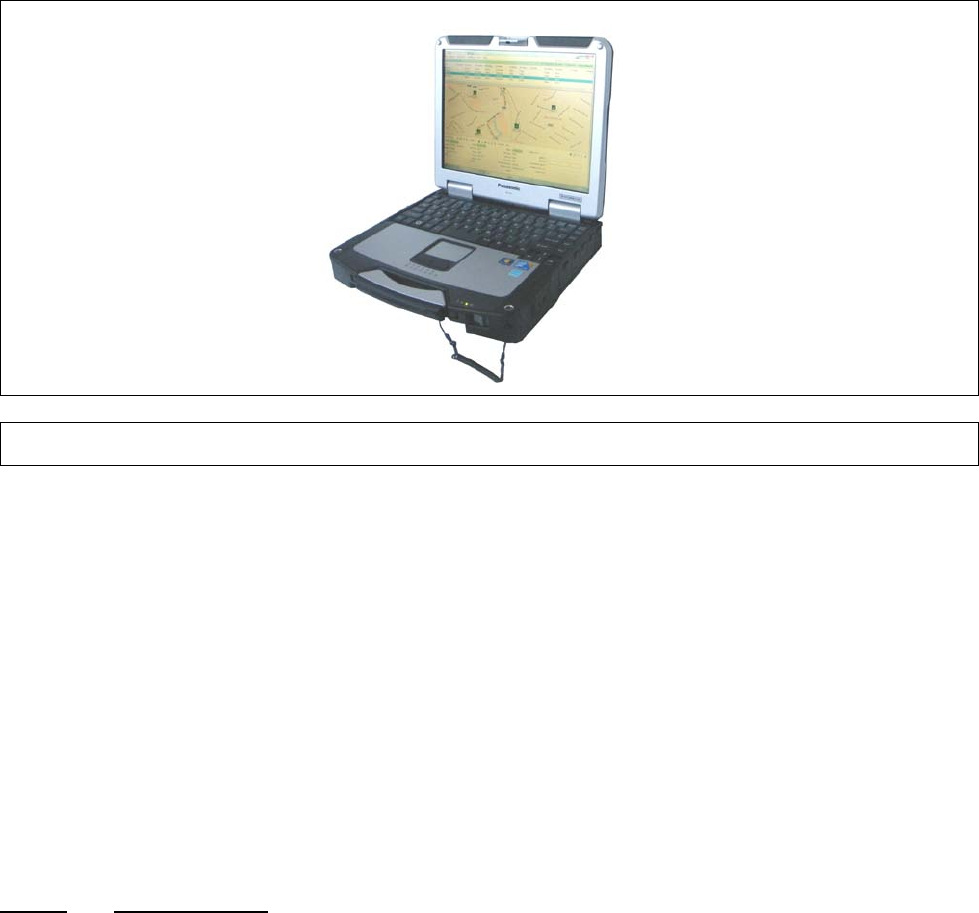
Figure 2 Laptop PC ...................................................................................................................... 3
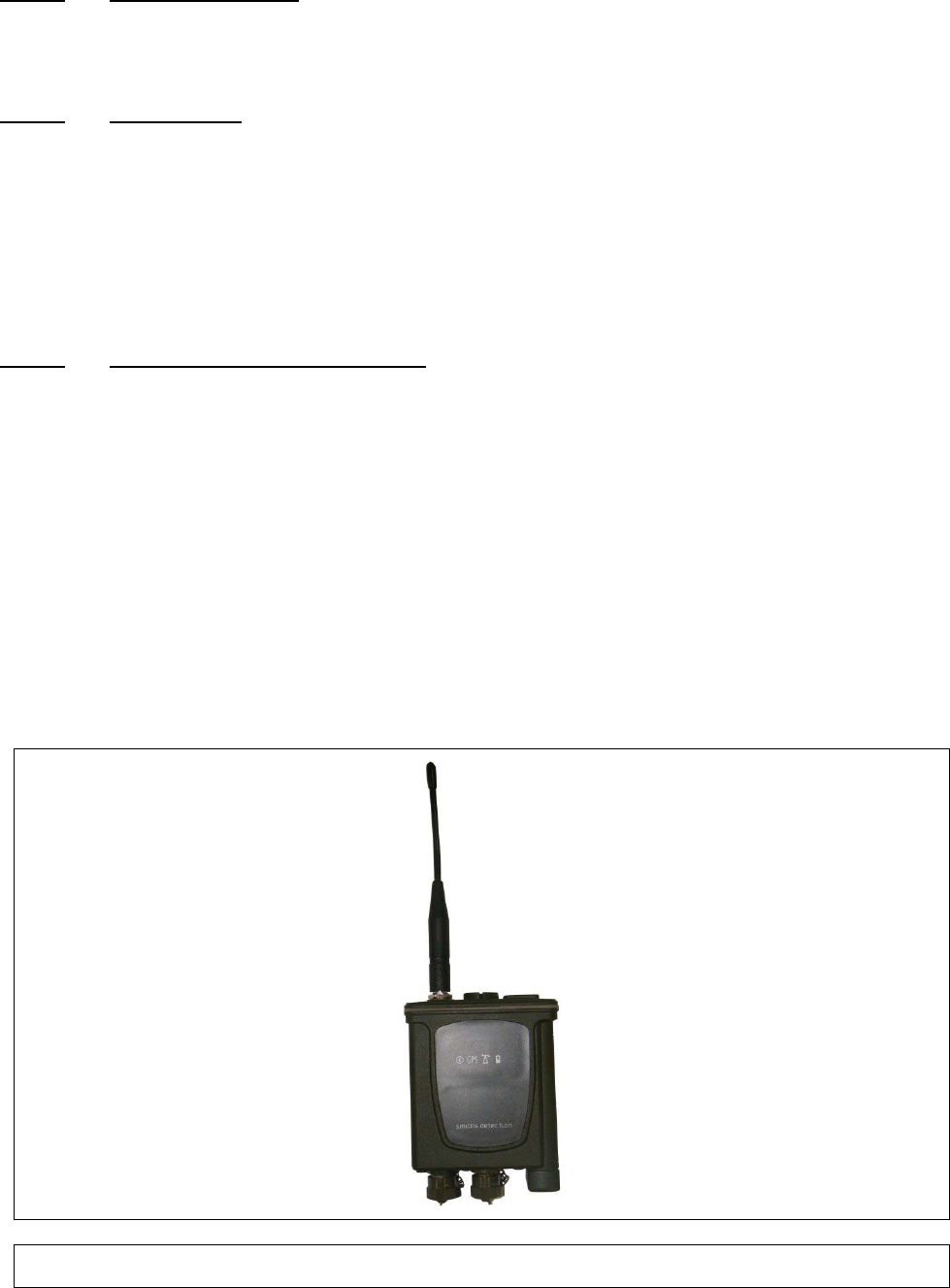
Figure 3 Sensor Node (Radio Modem) ......................................................................................... 4
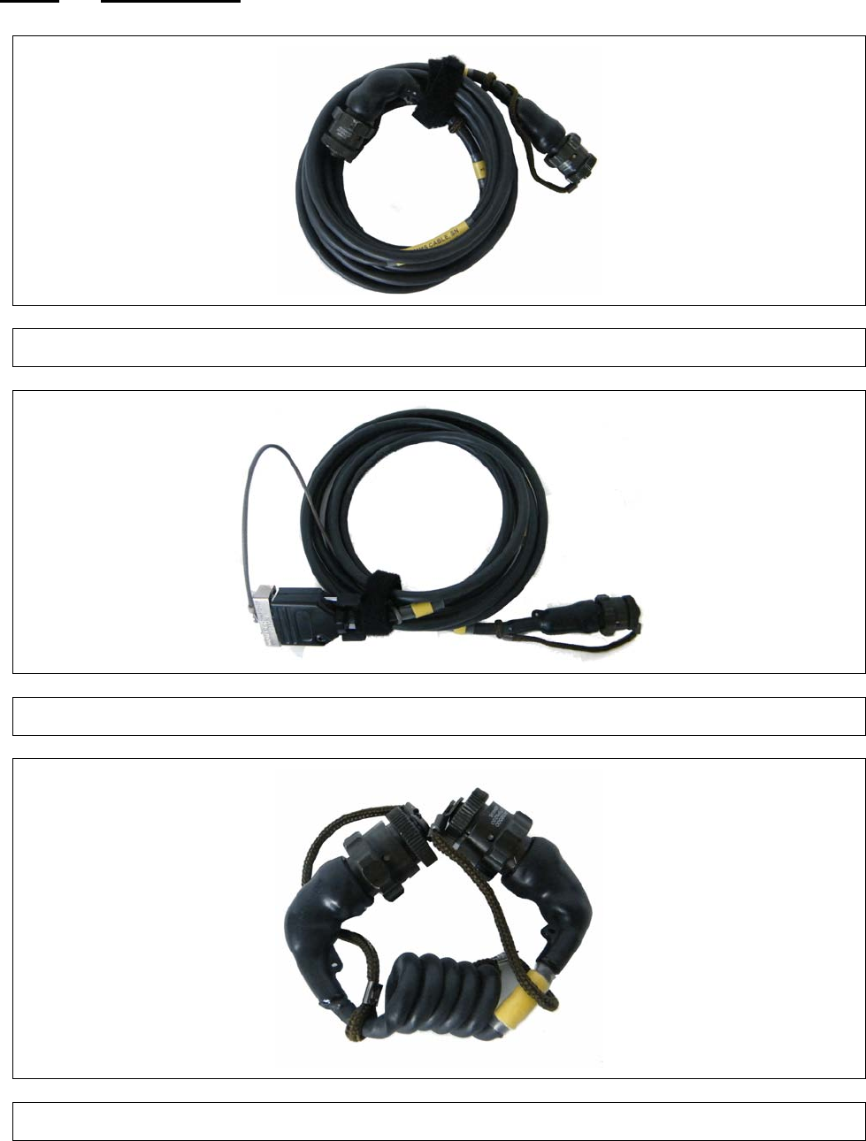
Figure 4 Detector to SN Comms Cable (20172) ........................................................................... 7
Figure 5 Laptop PC to BSN Comms Cable (20173) ..................................................................... 7
Figure 6 Short Spiral Comms Cable (20175)................................................................................ 7
Figure 7 Spiral Comms Cable (20234) ......................................................................................... 8
Figure 8 Mains Power Cable (5356-5085) .................................................................................... 8
Figure 9 Mains Travel Adaptor (3370-2506) ................................................................................. 8
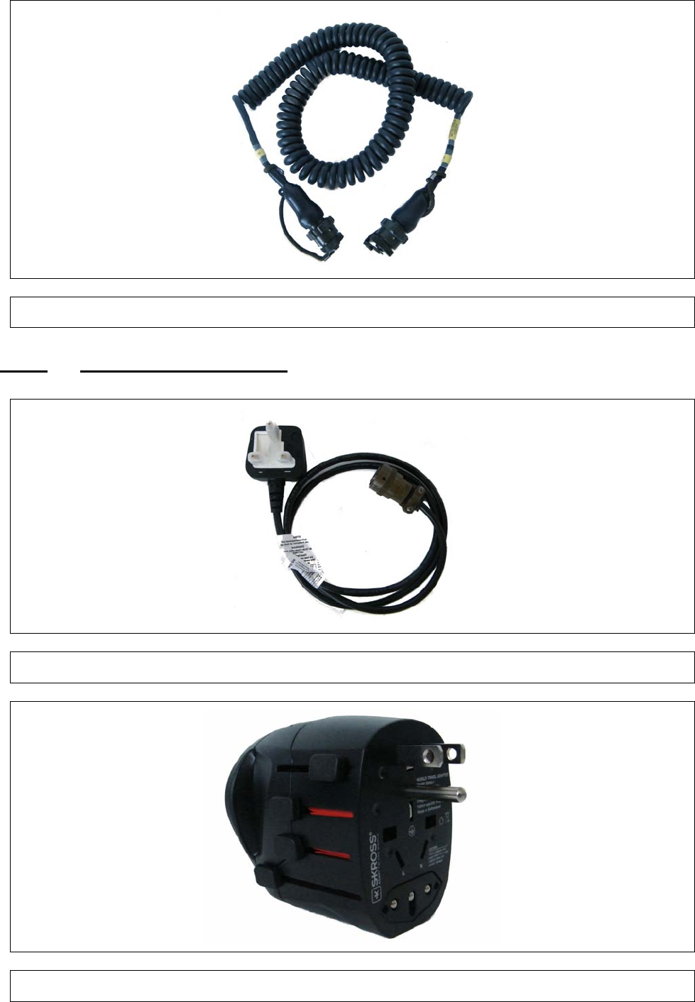
Figure 10 Power and Comms Cable (20553) ................................................................................. 9
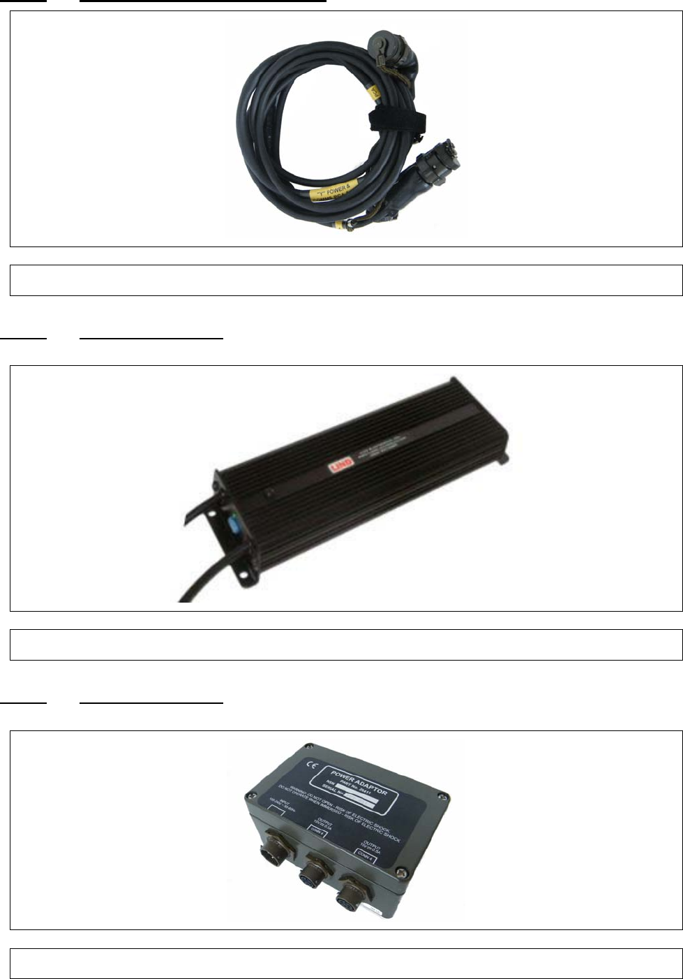
Figure 11 DC-DC Transformer(3330-5120) .................................................................................... 9
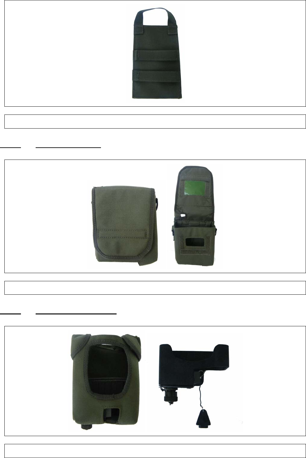
Figure 12 AC-DC Transformer (20734 [Green] or 20734A [Black]) ................................................ 9
Figure 13 Nexus Mounting Bracket (20466) ................................................................................. 10
Preliminary Pages
Page v
Figure 14 PCA Mounting Bracket (20336) ................................................................................... 10
Figure 15 Tripod Mounting Bracket (20330) ................................................................................. 10
Figure 16 Sensor Node PCA Mounting (20339) ........................................................................... 11
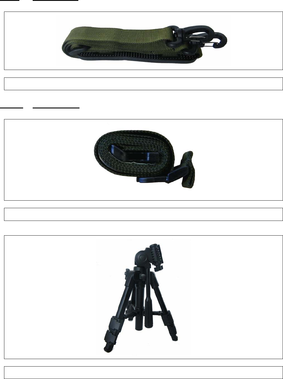
Figure 17 Sensor Node Pouches (20334) .................................................................................... 11
Figure 18 LCD3.3 Pouch (20335) with Dock (20420) ................................................................... 11
Figure 19 Shoulder Strap (5368-9020 [Green] or 19268 [Black]) ................................................. 12
Figure 20 Mounting Strap (20735 [Green] or 20735A [Black])...................................................... 12
Figure 21 Tripod (6881-0216) ...................................................................................................... 12
Figure 22 Laptop PC ................................................................................................................... 15
Figure 23 Radio Modem .............................................................................................................. 16
Figure 24 Pull-The-Dot Fastening ................................................................................................ 18
Figure 25 Interconnection Diagram for Base Station Node using Battery Power .......................... 23
Figure 26 Connect Button – C2 Program Main Window ............................................................... 24
Figure 27 Base Station Sensor Node Detail Panel ....................................................................... 24
Figure 28 ‘Open Map File’ Button ................................................................................................ 25
Figure 29 Map / Image file dialog ................................................................................................. 25
Figure 30 Interconnection Diagram for the Sensor Node using Battery Power ............................. 27
Figure 31 Interconnection Diagram for the Sensor Node using Mains Power .............................. 28
Figure 32 Alarm Pop-up Window ................................................................................................. 29
Figure 33 Windows ‘Help and Support’ ........................................................................................ 33
Figure 34 Power Management Pop-up Window ........................................................................... 33
Figure 35 Sensa-LINX C2 Main Window...................................................................................... 35
Figure 36 ATP-45 Report Dialog .................................................................................................. 39
Figure 37 Folder Options Dialog .................................................................................................. 40
Figure 38 System Preferences Dialog ......................................................................................... 41
Figure 39 Map Icons Legend Window .......................................................................................... 42
Figure 40 Connect Dialog ............................................................................................................ 43
Figure 41 Add Single Sensor Node Dialog ................................................................................... 44
Figure 42 Add multiple Sensor Nodes Dialog .............................................................................. 44
Figure 43 Sensor Node List ......................................................................................................... 45
Figure 44 Map Panel ................................................................................................................... 47
Figure 45 Base Station Panel ...................................................................................................... 49
Figure 46 Base Station Information Window ................................................................................ 50
Figure 47 Base Station Settings Dialog ....................................................................................... 51
Figure 48 Sensor Node Panel ...................................................................................................... 51
Figure 49 Sensor Node Information Window ............................................................................... 52
Figure 50 Sensor Node Tags Dialog ............................................................................................ 53
Figure 51 Multiple Sensor Node Tags Dialog ............................................................................... 54
Figure 52 Sensor Node Settings Dialog ....................................................................................... 54
Figure 53 Multiple Sensor Node Settings Dialog .......................................................................... 54
Figure 54 Sensor Panel ............................................................................................................... 55
Figure 55 Sensor Information Window ......................................................................................... 57
Figure 56 Sensor Settings ........................................................................................................... 57
Figure 57 Sensor Settings (Multiple Sensors) .............................................................................. 58
Figure 58 Alarms Window – Alarms History ................................................................................. 58
Figure 59 Alarms Window – Active Alarms .................................................................................. 60
Figure 60 Warnings Window ........................................................................................................ 60
Figure 61 Events Window ............................................................................................................ 61
Figure 62 Sensor Node Batteries or Battery Cassette Replacement ............................................ 71
Figure 63 Radio Modem Antenna Replacement .......................................................................... 73
Figure 1 Hardware Configuration .............................................................................................. A-5
Figure 2 NCT Main Screen Showing the current Sensor Node settings .................................... A-7
Figure 3 Destination Folder Access Denied Dialog ................................................................. A-11
Figure 4 Reprogram Warning Dialog ...................................................................................... A-12
Figure 5 Starting OS Update Dialog ........................................................................................ A-12
Figure 6 Loader Error Dialog .................................................................................................. A-12
Figure 7 MfgTool Main Screen ................................................................................................ A-12
Figure 8 MfgTool Connected .................................................................................................. A-13
Figure 9 MfgTool Busy ............................................................................................................ A-13
Preliminary Pages
Page vi
Figure 10 Update Sensor Node Application Dialog ................................................................... A-14
Figure 11 Connecting to the sensor node dialog ....................................................................... A-15
Figure 12 Select sensor node application file dialog.................................................................. A-15
Figure 13 Unable To Initialize Connection Dialog ...................................................................... A-15
Figure 14 Select Sensor Node Application File Dialog .............................................................. A-16
Figure 15 Start Update Dialog ................................................................................................... A-16
Figure 16 Application Completed Successfully Dialog ............................................................... A-16
Figure 17 Application Update Failed Dialog .............................................................................. A-17
Figure 18 Copy Sensor Logs Dialog ......................................................................................... A-17
Figure 19 Copying Sensor Node Log Files Dialog ..................................................................... A-18
Figure 20 Copy Complete dialog ............................................................................................... A-18
Figure 21 NCT Main Screen ..................................................................................................... A-19
Figure 22 File Menu .................................................................................................................. A-19
Figure 23 Tools Menu ............................................................................................................... A-20
Figure 24 Radio Key ................................................................................................................. A-20
Figure 25 Help Menu ................................................................................................................ A-21
Figure 26 About Dialog ............................................................................................................. A-21
Figure 27 Get and Set Buttons .................................................................................................. A-22
Figure 28 Installer language select dialog ................................................................................. A-23
Figure 29 Installer welcome dialog ............................................................................................ A-24
Figure 30 Installer license agreement dialog ............................................................................. A-24
Figure 31 Installer choose components dialog .......................................................................... A-24
Figure 32 Installer choose install location dialog ....................................................................... A-25
Figure 33 Installer start menu folder dialog ............................................................................... A-25
Figure 34 Installer key option dialog .......................................................................................... A-25
Figure 35 Installer setup complete dialog .................................................................................. A-26
Figure 36 MfgTool Configuration Dialog .................................................................................... A-26
Figure 37 MfgTool USB Ports Dialog ........................................................................................ A-27
Preliminary Pages
Page vii
FOREWORD
© Smiths Detection Limited
This document is of United Kingdom origin. It is provided in confidence under existing laws,
regulations and agreements covering the release of data, and shall be treated accordingly. The
information contained herein must not be duplicated, used by, or disclosed to others in whole, or in
part, for any purpose other than that intended at release.
The information contained within this document is proprietary data as written by Smiths Detection
and is not intended for further dissemination to other companies or third parties without authorisation
from Smiths Detection Watford UK. These are the legal requirements under the Export Control
Order 2008. These documents and information are controlled under licence UKGL/05/02729/1P.
Please note this document contains export controlled technical data. These commodities/technical
data are controlled for export by the U.S. State Department. They may not be transferred, trans-
shipped, on a non-continuous voyage, or otherwise disposed of outside of the United States, either
in their original form or after being incorporated into other end- items without the prior written
approval of the U.S. Department of State.
For further information or any other queries regarding equipment maintenance, servicing etc.
contact:
Customer Services
Smiths Detection Limited
459 Park Avenue
Bushey, Watford
Hertfordshire
Englandg65
WD23 2BW
Tel: +44 (0) 1923 658170
Fax: +44 (0) 1923 240285
e-mail: UKSupport@smithsdetection.com
Preliminary Pages
Page viii
This page is intentionally left blank

Preliminary Pages
Page ix
FCC & IC COMPLIANCE
Radio Regulations
This section is applicable to the 2.4GHz Standard, 2.4GHz International and 900MHz Standard Variants of the
Sensor Node only.
This equipment has been tested and found to comply with the limits for a Class B digital device, pursuant to
part 15 of the FCC Rules. These limits are designed to provide reasonable protection against harmful
interference in a residential installation. This equipment generates, uses and can radiate radio frequency
energy and, if not in-stalled and used in accordance with the instructions, may cause harmful interference to
radio communications. However, there is no guarantee that interference will not occur in a particular
installation. If this equipment does cause harmful interference to radio or television reception, which can be
determined by turning the equipment off and on, the user is encouraged to try to correct the interference by
one or more of the following measures:
— Reorient or relocate the receiving antenna.
— Increase the separation between the equipment and receiver.
— Connect the equipment into an outlet on a circuit different from that to which the receiver is
connected.
— Consult the dealer or an experienced radio/ TV technician for help.
This Class B digital apparatus complies with Canadian ICES-003. Operation is subject to the following two
conditions: (1) this device may not cause interference, and (2) this device must accept any interference,
including interference that may cause undesired operation of the device.
This radio transmitter has been approved to operate with the antenna types listed below with the maximum
permissible gain and required antenna impedance for each antenna type indicated. Antenna types not
included in this list, having a gain greater than the maximum gain indicated for that type, are strictly prohibited
for use with this device.
2.4GHz Standard: Panorama PCG2400-TNC.
2.4GHz International: Panorama PCX-W24-TNC.
900MHz Standard: Panorama PCG-TNC-921.
Cet appareil numérique de la classe B est conforme à la norme NMB-003 du Canada. L'exploitation est
autorisée aux deux conditions suivantes : (1) l'appareil ne doit pas produire de brouillage, et (2) l'utilisateur de
l'appareil doit accepter tout brouillage radioélectrique subi, même si le brouillage est susceptible d'en
compromettre le fonctionnement.
Le présent émetteur radio a été approuvé pour fonctionner avec les types d'antenne énumérés ci-dessous et
ayant un gain admissible maximal et l'impédance requise pour chaque type d'antenne. Les types d'antenne
non inclus dans cette liste, ou dont le gain est supérieur au gain maximal indiqué, sont strictement interdits
pour l'exploitation de l'émetteur.
2.4GHz Standard: Panorama PCG2400-TNC.
2.4GHz International: Panorama PCX-W24-TNC.
900MHz Standard: Panorama PCG-TNC-921.
To comply with FCC RF exposure compliance requirements, only the supplied accessories
(including the pouch) should be used with the equipment and the equipment must not be co-located
or operated in conjunction with any other antenna or transmitter.
Preliminary Pages
Page x
SAFETY SUMMARY
The following are general safety precautions and instructions that must be understood and applied
during phases of operation and maintenance to ensure personal health and safety and the
protection of the equipment. Warnings and Cautions are repeated elsewhere in this publication
where they are appropriate.
WARNINGS & CAUTIONS
Warnings, Cautions and general safety information notes are strategically placed throughout this
manual prior to operating or maintenance procedures, practices or conditions where considered
essential for the protection of personnel (WARNING) or equipment (CAUTION). A WARNING or
CAUTION will apply each time the related step is repeated. Before any task is started all Warnings
and Cautions included in this manual must be reviewed and understood and personnel must be
conversant with the safety precautions and any first aid instructions shown:
• On the labeling of the container the equipment is supplied in.
• In local Safety Precautions and Regulations.
The equipment does not present any significant hazard to personal safety during normal operations.
However, the Warnings and Cautions and general safety information notes that follow have been
identified as potential hazards if the equipment is damaged, mishandled or used incorrectly.
WARNINGS
WARNING – SENSOR NODE RF TRANSMISSIONS
THE SENSOR NODES TRANSMIT IN THREE DIFFERENT FREQUENCIES.
• RF ENERGY IN THE 902 TO 928 MHZ FREQUENCY RANGE AT POWERS UP
TO 0.158 WATTS (22 dBm).
• RF ENERGY IN THE 868 MHZ FREQUENCY RANGE AT POWERS UP TO 0.5
WATTS (27 dBm)
• RF ENERGY IN THE 2.4GHZ FREQUENCY RANGE
AT POWERS UP TO 0.1
WATTS (20 dBm)
THIS MAY CAUSE ACTIVATION OF RADIO CONTROLLED EQUIPMENT SUCH AS
IMPROVISED EXPLOSIVE DEVICES (IED). SENSOR NODES SHOULD NOT BE USED
IN CIRCUMSTANCES WHERE RF TRANSMISSIONS COULD CAUSE A HAZARD TO
PERSONNEL.
WARNING - DAMAGE TO PERSONAL PROTECTIVE EQUIPMENT
PERSONAL PROTECTIVE EQUIPMENT CAN BE TRAPPED OR PINCHE
D WHEN
OPERATING THE EQUIPMENT. MAKE SURE THAT THE INTEGRITY OF THE
NBC
SUIT AND GLOVES IS NOT COMPROMISED WHILST OPERATING THE EQUIPMENT.
WARNING – BATTERIES
THE SENSOR NODE CAN USE EITHER LITHIUM IRON DISULFIDE AA BATTERIES
OR ALKALINE MANGANESE DIOXIDE AA BATTERIES. THESE BATTERIES ARE A
FLAMMABLE, CORROSIVE AND VAPOUR HAZARD. THE LITHIUM IRON DISULFIDE
BATTERIES CONTAIN, LITHIUM, IRON DISULFIDE, AND AN ELECTROLYTE. THE
LITHIUM REACTS VIGOROUSLY WHEN IMMERSED IN WATER. THE ELECTROLYTE
IS FLAMMABLE AND HIGHLY CORROSIVE.
Preliminary Pages
Page xi
DO NOT IMMERSE BATTERIES IN WATER, DECONTAMINANT SOLUTION OR
OTHER LIQUIDS.
DO NOT CRUSH OR BURN BATTERIES.
DO NOT ATTEMPT TO RECHARGE NON-RECHARGEABLE BATTERIES.
DO NOT STORE BATTERIES AT TEMPERATURES ABOVE 70°C (158°F).
IN THE EVENT THAT A BATTERY WITHIN THE SENSOR IS SHORTED OR
DAMAGED IT SHOULD BE REMOVED FROM THE UNIT AND DI
SPOSED OF
ACCORDING TO LOCAL PROCEDURES FOR HAZARD
OUS WASTE. SUITABLE
PROTECTIVE CLOTHING SHOULD BE WORN WHEN HANDL
ING SUSPECTED
BATTERIES. IF THE SKIN OR EYES COME INTO
CONTACT WITH THE
ELECTROLYTE, WASH THOROUGHLY WITH WATER
AND SEEK MEDICAL
ATTENTION.
WARNING – DANGEROUS SUBSTANCES - CHEMICAL WARFARE AGENTS
AFTER A LIVE CHEMICAL WARFARE AGENT ATTACK EQUIPMENT MAY BE
CONTAMINATED BY HARMFUL SUBSTANCES WHICH COULD CAUSE INJURY TO
PERSONNEL. BEFORE ANY MAINTENANCE ACTIVI
TY IS PERFORMED
EQUIPMENT USED IN A LIVE CHEMICAL WARFARE AGENT ATTACK SHOULD BE
DECONTAMINATED.
WARNING - RISK OF EXPLOSION
SENSOR NODES MAY PROVIDE AN IGNITION SOU
RCE IN AN EXPLOSIVE
ATMOSPHERE DUE TO RF TRANSMISSIONS. DO NOT USE THE SENSOR NOD
ES IN
AN ENVIRONMENT WHERE EXPLOSIVE VAPOURS ARE PRESENT.
WARNING – DANGEROUS SUBSTANCES - SODIUM HYPOCHLORITE
SODIUM HYPOCHLORITE LIQUID AND SOLUTION CAUSE IRRITATION TO THE
SKIN AND THE DIGESTIVE SYSTEM IF INGESTED. VAPOUR CAUSES IRRITATION
TO THE EYES AND THE RESPIRATORY SYSTEM. PROTECT THE SKIN AND DO
NOT SWALLOW SODIUM HYPOCHLORITE LIQUID OR SOLUTION. DO NOT INHALE
OR EXPOSE THE EYES TO THE VAPOUR. WEAR FULL PERSONAL PROTECTION
EQUIPMENT (PPE) WHEN DECONTAMINATING EQUIPMENT.
DO NOT MIX SODIUM HYPOCHLORITE WITH ANY OTHER SOLUTIONS AS THIS
MAY CREATE TOXIC COMPOUNDS AND FUMES.
DISPOSE OF ALL SOLUTIONS, MATERIALS, AND PPE USED AS CONTAMINATED
WASTE.
WARNING – ELECTRIC SHOCK
SENSOR NODES CAN BE POWERED BY BATTERIES, AN EXTERNAL DC SUPPLY
OR AN EXTERNAL AC POWER SUPPLY. TO PREVENT ELECTRIC SHOCK MAKE
SURE THAT THE SENSOR NODE IS SWITCHED OFF AND
THE BATTERIES ARE
REMOVED OR THE EXTERNAL POWER SUPPLY IS DISCONNECTED PRIOR TO
PERFORMANCE OF ANY MAINTENANCE ACTIVITY.
Preliminary Pages
Page xii
WARNING - TOXIC HAZARD
TOXIC SUBSTANCES MAY BE RELEASED IF THE SENSOR NODE
CATCHES FIRE
OR IS BURNED AS A MEANS OF DISPOSAL. DO NOT DISPOSE OF IN FIRE.
WARNING - TRIP HAZARD
WHEN THE SENSA-LINX DETECTOR NETWORKING SYSTEM IS IN USE THE
RE ARE
CABLES THAT CAN CAUSE TRIP HAZARDS. ALWAYS ROUTE THE CABLES
TO
AVOID TRIPPING POSSIBILITIES FOR CROSSING PERSONNEL.
WARNING - BURNS
IF THE OUTER COVER OF A BATTERY INSTALLED IN THE BATTERY CASSETTE
IS
DAMAGED, A SHORT CIRCUIT CAN OCCUR AND THE BATTERIES MAY OVE
RHEAT.
ALWAYS CHECK THAT THE OUTER COVER OF EACH BATTERY IS UNDAM
AGED
BEFORE INSTALLING IN THE BATTERY CASSETTE.
WARNING – EFFECTIVE DECONTAMINATION
A SINGLE DECONTAMINATION OF THE LAPTOP PC USING HAND-
HOT (100ºF
(38ºC)) SOAPY WATER MAY NOT BE SUFFICIENT TO REMOVE ALL HARMFUL
CONTAMINATION. DECONTAMINATION SHOULD BE
REPEATED UNTIL ALL
HARMFUL CONTAMINATION IS REMOVED FROM THE LAPTOP PC. PERSONNEL
SHOULD CONTINUE TO USE PERSONAL PROTECTIVE EQUIPMENT UNTIL FULL
DECONTAMINATION IS CONFIRMED. IF FULL DECONTAMINAT
ION CANNOT BE
CONFIRMED THE LAPTOP PC SHOULD BE DISPOSED OF AS CONTAMINATED
EQUIPMENT AND A REPLACEMENT ITEM OBTAINED.
WARNING – UNTRAINED PERSONNEL
THE SENSOR NODE CONTAINS COMPONENTS THAT CAN BE HAZARDOUS TO
PERSONNEL. A TRAINED OPERATOR CAN PERFORM
ONLY THOSE
MAINTENANCE TASKS SHOWN IN THE HANDBOOK AND USERS GUIDE. FOR ALL
OTHER REPAIRS THE SENSOR NODE MUST BE RETURNED TO THE
MAINTENANCE CONTRACTOR/MANUFACTURER.
WARNING – BATTERY DISPOSAL
BATTERIES CONTAIN HAZARDOUS SUBSTANCES.
ALWAYS DISPOSE OF
BATTERIES AS HAZARDOUS WASTE IN ACCORDAN
CE WITH LOCAL
RECOMMENDED PROCEDURES.
WARNING – RISK OF ELECTRIC SHOCK
THERE IS A REMOTE POSSIBILITY OF ELECTRIC SHOCK WHEN USING THE
POWER SUPPLY UNIT IN WET CONDITIONS. USE ONLY 110 V AC SUPPLY WHEN
OPERATING THE POWER SUPPLY UNIT OUTDOORS. BEFORE USE INSPECT THE
POWER CABLE AND POWER SUPPLY UNIT TO ENSURE THAT THERE IS NO
DAMAGE. DO NOT OPERATE THE POWER SUPPLY UNIT WHEN EITHER THE
POWER SUPPLY UNIT OR THE CABLE IS IMMERSED IN WATER.
Preliminary Pages
Page xiii
WARNING – LAPTOP PC BATTERY
THE LAPTOP PC CONTAINS A LITHIUM ION BATTERY PACK WHICH CAN EXPLODE
IF NOT PROPERLY REPLACED, USED, HANDLED OR DISPOSED OF CORRECTLY.
DISPOSE OF THE BATTERY AS REQUIRED BY LOCAL REGULATIONS. USE ONLY
BATTERIES RECOMMENDED BY THE COMPUTER MANUFACTURER.
WARNING – LAPTOP PC HIBERNATION AND LOST COMMUNICATIONS
THE SENSA-LINX SYSTEM COMMUNICATION WITH THE BASE STATIO
N NODE
WILL STOP WHEN THE LAPTOP PC RUNNING THE C2 PROGRAM
GOES INTO
HIBERNATION (SLEEP MODE). WHILE THE LAPTOP PC IS IN HIBERNATION ANY
SENSOR NODE ALARMS AND OTHER INFORMATION WILL NOT BE RECEIVED BY
THE LAPTOP PC AND SOME DATA MAY BE LOST (NOT RECORDED) EVEN AFTER
COMMUNICATION IS RESUMED. TO ENSURE THAT ALL SENSOR NODE ALARMS
AND OTHER INFORMATION ARE RECIVED BY THE LAPTOP PC AND THAT ALL
DATA IS RECORDED MAKE SURE THE LAPTOP PC IS SET UP SO THAT IT DOES
NOT HIBERNATE.
WARNING – HEAVY EQUIPMENT
A FULLY LOADED TRANSIT CASE HAS AN OV
ERALL WEIGHT OF
APPROXIMATELY 21KG. HEAVY ITEMS IF LIFTED INCO
RRECTLY MAY CAUSE
HARM TO THE OPERATORS. OBSERVE MANUAL HANDLING GUIDELINES AND
FOLLOW LOADING GUIDELINES INDICATED ON EQUIPMENT. OBTAIN HELP AS
REQUIRED WHEN LIFTING OR MOVING HEAVY ITEMS.
WARNING – EXPOSURE TO RADIO FREQUENCY ENERGY.
THIS DEVICE TRANSMITS RADIO FREQUENCY ENERGY. WHEN WORN ON THE
BODY, ONLY THE SUPPLIED ACCESSORIES (INCLUDING THE POUCH) MAY BE
USED WITH THE EQUIPMENT AND THE EQUIPMENT MUST NOT BE CO-LOCATED
WITH OR OPERATED IN CONJUNCTION WITH ANY OTHE
R ANTENNA OR
TRANSMITTER
CAUTIONS
CAUTION – Use of Sensor Nodes in wet weather
The SENSA-LINX Sensor Nodes and Laptop PC
contain electronic components
which can be damaged by water.
In heavy rainfall conditions make sure equipment
battery compartments are fully closed against water ingress
and the antenna is
installed to the Sensor Node.
CAUTION - Radio Modem Frequency Band
The Sensor Nodes
use a frequency band that is available for use by other
unlicensed RF devices. Such devices may interfere with the operation of the Sensor
Nodes or may be interfered with by the Sensor Nodes. The Sensor Nodes
incorporate features to minimise such interference but performance may be
degraded. Check the location and frequency of other RF devices in the area before
operating the Sensor Nodes.
Preliminary Pages
Page xiv
CAUTION – Incorrect Connections
There are two connectors on the Sensor Node
. These connectors are keyed to
prevent misconnection but damage may occur if an incorrect connection is
attempted forcefully. Check that the correct connector is bein
g used before
connection. Make connections carefully and do not force connection
if resistance is
felt.
CAUTION – User Serviceable Components
The Sensor Node contains no user serviceable components. Attempted access by
untrained personnel may render the
unit unserviceable. Do not attempt to gain
access to the interior of the unit.
CAUTION – Incorrect Insertion of Batteries
Batteries inserted into the Sensor Node in the incorrect orientation may cause
damage. Always make sure batteries are inserted in the correct orientation.
CAUTION – Corrosion Due To Battery Leakage
Batteries must not be left in the Sensor Node if it will not be
used for a period of
time in case of leakage, which will cause corrosion. Make sure that the batteries are
removed from the Sensor Node prior to any storage period.
CAUTION – Mixing Battery Types
Using both
lithium and alkaline battery types within the Battery Cassette may cause
damage to the Sensor Node. Do not use both lithium and alkaline battery types at
the same time within the Battery Cassette.
CAUTION – Siting of Equipment
The Sensor Node can benefit from ‘line-of-sight’ for effective communication when
near the limits of its transmission range. If th e Sensor Node
is incorrectly sited,
proper communication may not be established with its paired Sensor Node. Ensure
the Sensor Node is correctly sited.
CAUTION – Equipment Contamination
Contamination such as dirt and fluids can enter the interior of the Sensor Node
through the Battery Cassette compartment. This may cause the Sensor Node
to
malfunction or cease to operate altogether. Make sure that the Battery Cassette is
removed only when required and reinstalled as soon as possible.
CAUTION – Equipment damage
The Sensor Node contains components that may be damag
ed by water or other
liquids. To prevent fluid from entering the equipment make sure the
Sensor Node
Battery Cassette and Antenna are properly installed prior to cleaning or
decontamination.
Preliminary Pages
Page xv
CAUTION – Sodium hypochlorite
Sodium hypochlorite is a strong oxidiser and could cause damage to the laptop PC
if used for decontamination. It is recommended that only hand-hot (38ºC (100ºF))
soapy water is used to decontaminate the laptop PC.
CAUTION – Inaccurate Contamination Spread Prediction
In ATP -45 reports
the “height” field will default to zero (this field represents the
height above ground level, not altitude, and this cannot be acquired from the GPS).
This may give inaccurate results if used to predict the spread of contamination
when the sensor is positi
oned at a significant height above ground level (e.g. on a
tall building). If using ATP-45 reports to predict contamination spread; either
position sensors at ground level, or set the ATP-45 mode to ‘Manual ATP-45’ and
edit the “height” field to a realis tic value.
CAUTION – Battery Power Discharge
Batteries left in the Sensor Node
will discharge over a period of time even when the
equipment is switched off.
The expected battery life may be significantly reduced if
a Sensor Node has stored containing batteries. If the Sensor Node will not be used
for a period of time, m
ake sure that the batteries are removed prior to any storage
period.
CAUTION – Equipment damage.
The
Laptop Power Supply is rated to be connected to supplies from 100V to 240V
AC at 50 to 60Hz. Connecting to a supply outside of this range may cause damage
to the equipment.
Do not connect the Laptop Power Supply to an external power
source outside the stated range.
CAUTION – Equipment damage.
The AC to DC transformer is rated to be conne
cted to supplies from 100V to 280V
AC at 50 to 60Hz. Connecting to a supply outside of this range (e.g. using the Mains
travel Adapter) may cause damage to the equipment.
Do not connect the AC to DC
transformer to an external power source outside the stated range.
CAUTION – Reduced System Performance
Changing the Sensor Node Refresh Period and GPS Refresh Period can adversely
affect the performance of the Sensa-LINX system.
Setting the refresh rate too high
may result in system overload whereas setting t
he refresh rate too low may result in
lost data or non-
current data being displayed. Take care if changing the refresh
rates from their default settings (40 seconds for fixed nodes and 5 seconds for
mobile nodes). Revert to the default settings if issues occur.
Preliminary Pages
Page xvi
This page is intentionally left blank

Preliminary Pages
Page xvii
REVISION RECORD
Issue Incorporated By Date
Initial Issue Manufacturer December 2011
Preliminary Pages
Page xviii
This page is intentionally left blank
Chapter 1
Page 1
CHAPTER 1 INTRODUCTION
1.1 SCOPE OF THIS MANUAL
This manual provides set up and operating instructions for the Sensa-LINX Detector Networking
System, information on the safe use and care of the equipment, operator maintenance procedures
with some basic troubleshooting, and a list of repair parts and consumables.
1.2 SYSTEM OVERVIEW
The Sensa-LINX Detector Networking System is equipment to allow a collection of sensors to be
combined into a network, wirelessly connected to a base station to provide centralized control and
monitoring of the data. Each sensor is connected to a Sensor Node (Radio Modem) which
communicates with another Sensor Node (Radio Modem) at the Base Station Node connected to
the Laptop PC (Base Station).
This system is intended for remote monitoring of an unmanned perimeter of sensors, monitoring a
network of worn sensors as personnel move through an area, collation of data from multiple sensors
into a single tactical map, and combinations of the above tasks.
The Laptop PC uses data acquired from the network of sensors to produce standard CBRNE report
messages.
The Sensor Nodes (Radio Modems) have built-in Global Positioning System (GPS) receivers that
obtain position co-ordinates. The GPS receiver is then disabled soon after start up to conserve
battery power. The GPS capability is re-enabled when the Sensor Node’s (Radio Modem’s)
accelerometer detects movement.
Due to operating restrictions in different countries, a number of Sensor Node (Radio Modem)
variants are offered. These include an International and Standard 2.4GHz variant, an International
and Standard 900MHz variant, and an International and Standard 868MHz variant. Each of these
has its own characteristics which can be seen in TABLE 2 Radio Modem Variants.
The Sensa-LINX system can currently interface to the Smiths Detection LCD3.3, LCD Nexus and
CAM XTR chemical sensors.
Figure 1 Base Station Node and Sensor Node Pelican Cases

Chapter 1
Page 2
1.3 GLOSSARY
TABLE 1. Abbreviations and Acronyms
Acronym/ Term
Definition
BIT Built In (Self) Test
BSN Base Station Node - Sensor Node connected directly to the Controller PC. The
‘base’ of the radio network from the perception of the host PC.
C2 Command and Control
CWA Chemical Warfare Agent
COM Communications Port
COMMS Communications
COTS Commercial Off The Shelf (equipment)
Detector LCD3.3 or LCD Nexus or CAM XTR (AKA Sensor)
GHz Gigahertz
GPS Global Positioning System
IBIT Initiated Built In Test
KHz Kilohertz
LCD Lightweight Chemical Detector
LED Light Emitting Diode
LOS Line Of Sight
MHz Megahertz
NEXUS Portable and highly sensitive and selective CWA and TIC detector
PBIT Periodic Built In Test
PC Personal Computer
POST Power On Self Test
PWM Pulse Width Modulation
Sensor LCD3.3 or LCD Nexus or CAM XTR (AKA Detector)
SN Sensor Node – Sensor Node connected to a detector. Acts as a message relay
between the host PC and the detector, so that the two can communicate without
being wired to each other.
SPI Serial Peripheral Interface
TIC Toxic Industrial Chemical
USB Universal Serial Bus
Georeferenced
A map that is georeferenced is one whose existence has been defined in
physical space.
1.4 EQUIPMENT OVERVIEW
1.4.1 Command & Control (C2) System
1.4.1.1 Laptop PC
The Laptop PC is provided to run the C2 software. Any laptop PC or other PC with the following
specification is capable of running the C2 application software and providing the command and
control function for the network of sensor nodes.
The Laptop PC runs Windows 7 Ultimate Edition and is pre-loaded with the Sensa-LINX C2
program. If there is a requirement to install the C2 Program onto a PC not supplied as part of the
Chapter 1
Page 3
Sensa-LINX equipment, the program can be loaded from the software support CD provided with the
Base Station Kit. Instructions for loading the Sensa-LINX C2 Program are given in Section 4.1 of this
manual. The PC onto which the Sensa-LINX C2 Program is to be installed should meet or exceed
the specification of the Panasonic Toughbook CF-31 shown below.
Figure 2 Laptop PC
The Laptop PC that can be supplied as part of the Sensa-LINX equipment is the Panasonic
Toughbook CF-31 which has the following specification:
• Processor: Intel Core i5-2520M 2.5GHz.
• Memory: 4 GB.
• Display: 1024*768 resolution full colour.
• RS232 port.
• Hard Disk Drive: 320 GB.
• DVD drive.
• Serial port and USB ports.
• A rechargeable battery.
• A power supply unit for connecting to an external AC supply.
• Good resistance to environmental factors including temperature, dust, rain and shock.
1.4.1.2 C2 Application
The Sensa-LINX C2 allows the user to set up and change networks, monitor status of the sensors
and sensor nodes including mapping their locations, make changes to sensor and sensor node
settings, and save logs of alarms, warnings and other events for later review.
Chapter 1
Page 4
1.4.2 Base Station Node/Sensor Node
1.4.2.1 Base Station Node
The base station node is physically connected to the Laptop PC via a communications cable and
forms the controlling point of the network topology.
1.4.2.2 Sensor Node
The role of the sensor node is to provide wireless communications capability for a deployed sensor
or act as a mesh repeater on the network. It can connect to the LCD3.3, LCD3.3 in Power & Comms
Adaptor (PCA), LCD NEXUS. and the CAM XTR.
The SN communicates with the base station node via a wireless network and as such will need to
remain within RF communications range in order to operate correctly. The RF range is dependent on
the type, density, RF frequency, and position of RF obstacles between the SN and BSN (see para
1.4.3 for more information on range capabilities).
1.4.2.3 Sensor Nodes (Radio Modems)
The Sensor Nodes are Radio Modems that are rugged, waterproof and tested to military standards
(see para 1.8.1 for details).
The Sensor Nodes (Radio Modems) have a number of variants (see para 1.4.3), each approved for
use in specific regions of the world. The Sensor Nodes (Radio Modems) have detachable antennas
and some variants use different antennas. It is important that they are operated only with the
antenna provided with them. Using different antennas (including antennas from other variants of
Sensor Nodes (Radio Modems)) will affect the radio performance of the unit and may breach local
regulations on transmission power.
The BSN and the SN are two different roles played by the same Sensor Node (Radio Modem).
When a Sensor Node (Radio Modem) is first powered up it assumes a SN role. If it is connected to
the Controller PC it will automatically switch to a BSN role after communicating with the Sensa-LINX
C2 software.
Figure 3 Sensor Node (Radio Modem)

Chapter 1
Page 5
1.4.3 Sensor Node (Radio Modem) Variants
TABLE 2. RADIO MODEM VARIANTS
Variant
Antenna
Approvals
Transmit
Power
(EIRP
dbm)
Freq.
Range
(MHz)
Theoretical Range
(metres) 1
Mesh
Capable
Indoor
/Urban
Outdoor
LOS
2.4GHz
International Panorama
PCX-W24-TNC FCC,
IC,
CE,
C-Tick,
Telec
12 2400.0 -
2483.5 50 200 Y
2.4GHz
Standard Panorama
PCG2400-TNC FCC,
IC,
C-Tick
20 2400.0 -
2483.5 100 500 Y
900MHz
Standard
Panorama
PCG-TNC-921
FCC,
IC
22
902 -
928
100
3000
Y
900MHz
International
Panorama
PCG-TNC-921
C-Tick
22
916 -
928
100
3000
Y
868MHz
Standard
Panorama
PCG-TNC-851
CE
27
869.4 -
869.65
200
7000
N
868MHz
International
Panorama
PCG-TNC-851
CE
5
869.4 -
869.65
100
800
N
1 These are Rough Order of Magnitude theoretical estimates. Actual ranges achieved will be highly
dependant on the location, conditions and the presence of other transmitters in the area and may be
considerably lower. “Outdoor LOS” range also assumes Line-Of-Sight between Sensor Nodes.
1.4.3.1 2.4GHz International
The 2.4GHz International variant has relatively low power and thus lower range than the Standard
2.4GHz node. This variant is approved for use in the USA, Canada, some European countries,
Australia and Japan. Check the label on the sensor node for approval details and check local
regulations before using it in any other locations.
1.4.3.2 2.4GHz Standard
The 2.4GHz standard variant is higher power than the International 2.4GHz variant resulting in
increased range but is not available for use in Europe or Japan. This variant is approved for use in
the USA, Canada and Australia. Check the label on the sensor node for approval details and check
local regulations before using it in any other locations.
1.4.3.3 900MHz Standard
The 900MHz Standard variant has some increased range of the Standard 2.4GHz variant but cannot
be used in many countries due to frequency restrictions. This variant is approved for use in the USA
and Canada only. Check the label on the sensor node for approval details and check local
regulations before using it in any other locations.

Chapter 1
Page 6
1.4.3.4 900MHz International
The 900MHz International variant is a slightly modified version of the Standard 900MHz variant to
meet Australian regulations. Power output (and thus range) is the same but it is more restricted in
frequency and thus may be more prone to interference. This variant is approved for use in Australia
only. Check the label on the sensor node for approval details and check local regulations before
using it in any other locations.
1.4.3.5 868MHz Standard
The 868MHz Standard variant is available for use in most of Europe with some restrictions. It has
significant increased range potential over the International 2.4GHz but is not suitable for use in
North America due to frequency restrictions. Note that the 868 variants cannot “mesh” - i.e. you
cannot use sensor nodes as repeaters to increase the range of data transmission. This variant is
approved for use in some European countries (but specifically not in Italy and Slovakia). Check the
label on the sensor node for approval details and check local regulations before using it in any other
locations.
1.4.3.6 868MHz International
The 868MHz International variant is the low power variant of the 868MHz standard. It meets specific
Italian and Slovakian restrictions. It has a lower transmit range compared to the standard 868MHz.
It may have a slight range advantage over the International 2.4GHz variant but is not suitable for use
in North America due to frequency restrictions. This variant is approved for use in some European
countries (including Italy and Slovakia). Check the label on the sensor node for approval details and
check local regulations before using it in any other locations.
1.5 ANCILLARIES
1.5.1 Packaging
The ancillaries section provides details of the packaging provided with the Sensa LINX system.
There are different levels of packaging on offer:
• 4 Node Sensor Node system
• Base Station system
• Individual Sensor Nodes (cardboard box packaging)
1.5.2 Consumables
The only consumable used by the Sensa-LINX system is batteries. For further information on battery
types see para 1.7.2.2.
1.5.3 Accessories
There are various Sensa-LINX accessories available which include the following:
• Comms cables (various types)
• Power cables
• Cable adaptors (‘Y’ piece)
• DC-DC transformer (laptop PC supply e.g. from a vehicle)
• AC-DC transformer
• Mounting brackets (various) – SN to sensor
• Sensor Node Pouch
• LCD3.3 Detector Pouch with Dock
• Shoulder strap
• Mounting strap
Chapter 1
Page 7
1.5.3.1 Comms Cables
Figure 4 Detector to SN Comms Cable (20172)
Figure 5 Laptop PC to BSN Comms Cable (20173)
Figure 6 Short Spiral Comms Cable (20175)
Chapter 1
Page 8
Figure 7 Spiral Comms Cable (20234)
1.5.3.2 Power Cables and Adaptors
Figure 8 Mains Power Cable (5356-5085)
Figure 9 Mains Travel Adaptor (3370-2506)
Chapter 1
Page 9
1.5.3.3 Combined Power & Comms Cable
Figure 10 Power and Comms Cable (20553)
1.5.3.4 DC-DC Transformer
Figure 11 DC-DC Transformer(3330-5120)
1.5.3.5 AC-DC Transformer
Figure 12 AC-DC Transformer (20734 [Green] or 20734A [Black])

Chapter 1
Page 10
1.5.3.6 Mounting Brackets
Figure 13 Nexus Mounting Bracket (20466)
Figure 14 PCA Mounting Bracket (20336)
Figure 15 Tripod Mounting Bracket (20330)
Chapter 1
Page 11
Figure 16 Sensor Node PCA Mounting (20339)
1.5.3.7 Sensor Node Pouch
Figure 17 Sensor Node Pouches (20334)
1.5.3.8 LCD3.3 Pouch with Dock
Figure 18 LCD3.3 Pouch (20335) with Dock (20420)
Chapter 1
Page 12
1.5.3.9 Shoulder Strap
Figure 19 Shoulder Strap (5368-9020 [Green] or 19268 [Black])
1.5.3.10 Mounting Strap
Figure 20 Mounting Strap (20735 [Green] or 20735A [Black])
Figure 21 Tripod (6881-0216)

Chapter 1
Page 13
1.6 DOCUMENTATION
The following documentation is provided with the Sensa-LINX system:
• Sensa-LINX Operator’s Manual (this document)
• PC Manual
• Sensa-LINX Quick Reference Guide
Sensor documentation is supplied with the sensors.
1.7 POWER OPTIONS
1.7.1 C2 Laptop PC
1.7.1.1 External
The Laptop PC is supplied with its own external power supply with a UK standard plug fitted. The
system is also provided with a Mains travel Adapter (see Figure 9) that can be used to adapt the UK
plug for use elsewhere in the world.
A DC to DC converter is also available as an option to power the laptop from a vehicle power outlet
(see Section 1.5.3.4).
1.7.1.2 Battery
The Laptop PC uses the Panasonic Lithium Ion battery pack, provided with the Laptop PC. Refer to
the manufacturer’s documentation for more information.
1.7.2 Sensor/Base Station Node
1.7.2.1 External
The Sensor Node/Base Station Node can be powered by an optional AC to DC transformer. This
transformer is fitted with a UK standard plug fitted. The system is also provided with a Mains travel
Adapter (see 1.5.3.2) that can be used to adapt the UK plug for use elsewhere in the world.
1.7.2.2 Battery
Any kind of COTS AA type batteries can be used to power the SN/BSN, although the design has
been specifically centred around the use of Lithium Iron, Alkaline and NiMH cells.
A software algorithm inside the SN/BSN provides the ability to estimate the current battery capacity
as a percentage of its maximum. The percentage remaining is communicated to the C2 application
as part of the SN/BSN status reporting message. The setting of the battery type is available from the
C2 application.
When the battery voltage drops below a threshold the battery LED on the front of the SN/BSN will
begin to flash. The threshold level used is dependent on the type of battery used and the
temperature measurement made by the SN/BSN.
The batteries are installed into a Battery Cassette prior to insertion into the Radio Modem. The unit
uses four AA-size batteries
1.7.2.2.1 Lithium Iron
Lithium batteries are recommended as this battery type gives the best battery life performance,
particularly at low temperatures.
1.7.2.2.2 Alkaline
Alkaline batteries can be used as an alternative but give a reduced performance, particularly at low
temperatures.

Chapter 1
Page 14
1.7.2.2.3 Nickel Metal Hydride (Rechargeable)
Nickel Metal Hydride rechargeable batteries may also be used.
1.8 OPERATING CHARACTERISTICS
1.8.1 Environmental
The Sensa-LINX equipment is designed to operate within the temperature range shown in TABLE 3
below.
TABLE 3. OPERATING TEMPERATURE RANGES
Radio Modem -32 °C (-25.6 °F) to 50 °C (122 °F)
Laptop PC 5 °C (41 °F) to 35 °C (95 °F)
Chapter 2
Page 15
*1 CHAPTER 2 OPERATING INFORMATION
2.1 EQUIPMENTS CONTROLS AND INDICATORS
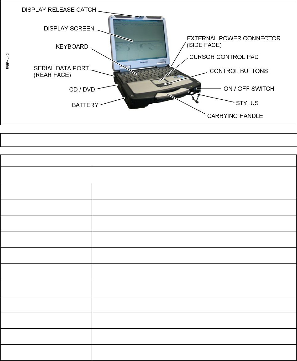
2.1.1 Laptop PC – Controls and Features
The Laptop PC has the following controls. For further information on the controls and their functions
see TABLE 4 below.
Figure 22 Laptop PC
TABLE 4. LAP TOP PC CONTROLS AND FEATURES
Feature Function
Power Connector Connection of external power supply
Cursor Control Pad Controls the cursor on the screen display
Control Buttons Left and right click buttons for cursor
ON / OFF Switch Switches the Laptop PC ON and OFF
Carrying Handle Carrying closed laptop PC
Battery Pack Slot For insertion and removal of internal re-chargeable battery pack
Serial Data Port Connection of Sensor Node
Keyboard Standard QWERTY keyboard
Display Screen LCD display
Display Release Catch Catch to hold display shut and release when required
Stylus Screen pointing device for use with ‘touch-screen’ functionality.
Chapter 2
Page 16
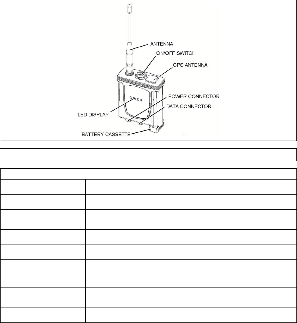
2.1.2 Sensor Node (Radio Modem)
The Sensor Node (Radio Modem) has the following controls. For further information on the controls
and their functions see TABLE 5.
Figure 23 Radio Modem
TABLE 5. CONTROLS AND FUNCTIONS
Control Function
Antenna Provides radio connection between the BSN and the SNs.
ON / OFF Switch Switches the Sensor Node (Radio Modem)
ON and OFF. This is a
latching connector requiring press / release operation.
GPS Antenna Provides positional information to system.
Battery Cassette Houses the batteries.
Data Connector Allows connection of the Sensor Node (Radio Modem) to the Controller
PC or to a LCD3.3 or LCD Nexus or CAM XTR detector using the
supplied cable.
Power Connector Allows connection of the Sensor Node (Radio Modem) to an external AC
power supply using the cable supplied.
LED Display Provides information to the operator using 4 LED’s.
2.1.3 Sensor Node Initial Configuration
The Sensor Node is delivered ready for operation with some settings pre configured. If there is a
requirement to change these settings, refer to Appendix A for detailed information on configuring
sensor nodes.
Chapter 2
Page 17
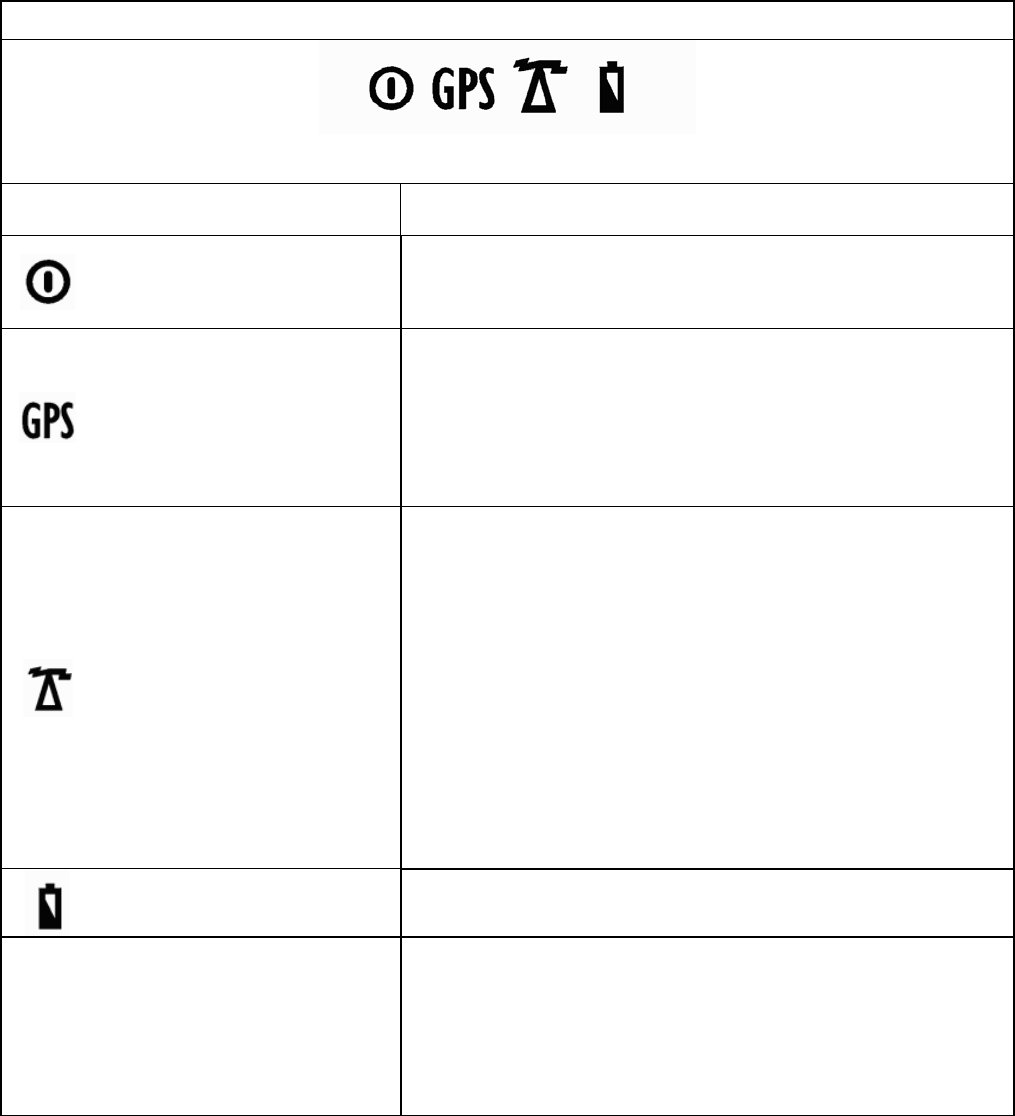
2.1.4 Sensor Node (Radio Modem) User Interface
The Sensor Node (Radio Modem) display consists of four LED’s, three green and one amber. For
information on the indications and their meanings see TABLE 6.
TABLE 6. LED FUNCTIONS
Illuminated icons as viewed on front of Radio Modem
Icon and LED Function
Green LED - Power
On - External power.
Pulse - Battery Power.
Off – Radio Modem switched off or no power
Green LED –
GPS, BIT
Indicator
Off – GPS ‘Powered Off’. GPS in power save mode.
Single Blink –GPS powered on; currently seeking ‘Fix’.
Double Blink – GPS powered on; has 2D ‘Fix’ i.e. latitude
and longitude but not altitude.
Triple Blink – GPS powered on; has 3D ‘Fix’ i.e. latitude,
longitude and altitude.
Continuous Rapid Blink – GPS BIT errors detected
Green LED -
Radio Link
Indicator
Short Triple Pulse - Strong radio link achieved and Sensor
Node is transmitting.
Long Triple Pulse - Strong radio link achieved but Sensor
Node is not transmitting.
Short Double Pulse - Good radio link achieved and Sensor
Node is transmitting.
Long Double Pulse - Good radio link achieved but Sensor
Node is not transmitting.
Short Single Pulse - Poor radio link has been achieved and
Sensor Node is transmitting.
Long Single Pulse - Poor radio link has been achieved but
Sensor Node is not transmitting.
Off - Radio link has not been achieved
Amber LED - Battery Low Pulse - Low battery power.
Off - Good battery power or external power.
All indicators for POST BIT
and Initiated BIT Tests only.
(Periodic BIT will not blink
the LED’s as this will
interfere with normal
operating mode).
On application of power, the power, radio, and battery lights
come on as a test. Then the power light goes off and the
radio and battery lights remain on while the unit is booting.
On – In the event POST or Initiated BIT test detects a
catastrophic failure – all indicators remain illuminated if
possible.
When pulsing, all LED’s on the Sensor Node pulse together. The brightness of the Sensor Node
LEDs is ‘persistent’ so that, when switched on, the brightness is the same as the last time the
Sensor Node was used. If the brightness setting of the Sensor Node LEDs does not match the
brightness setting of the detector display a warning will be shown in the C2 application on the PC at
the Base Station Node indicating that the settings are different. This warning is recorded in the
Warnings Log. The Sensor Node LED brightness setting can be changed only via the controls in the
C2 application on the Base Station Node PC. The brightness cannot be adjusted on the Sensor
Chapter 2
Page 18
Node itself. The brightness of the detector display can be adjusted using the controls in the C2
application also or can be adjusted at the detector using the detector controls. For further
information refer to the detector Operators’ Manual.
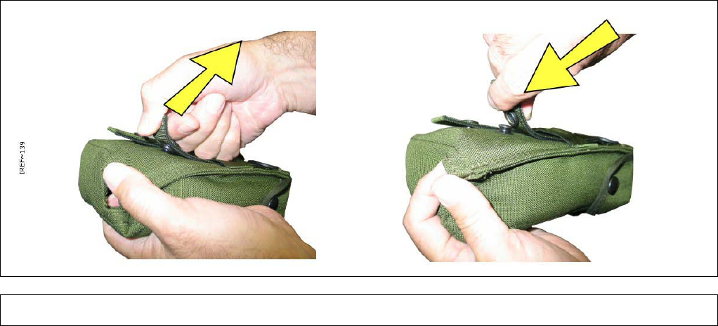
2.2 ‘PULL THE DOT’ FASTENERS
Some of the equipment pouches use ‘Pull-The-Dot’ fasteners. These press studs are manufactured
in such a way that they press together and come apart in only one particular direction making them
suitable for resisting significant forces when fastened so that they will not come apart, even under
stressed loading, unless correctly unfastened.
With reference to Figure 24, observe the fastener for the dot marked on the cap. To open the
fastener pull up and back in the opposite direction to the dot. To close the fastener push down and
forward in the direction of the dot.
Figure 24 Pull-The-Dot Fastening

Chapter 2
Page 19
2.3 SENSA-LINX NETWORK SET UP & OPERATION
The Sensa-LINX network set up and operation sequence should be followed in order as shown
below:
1. Unpack and check the Sensa-LINX Detector Networking System equipment. See section 2.3.1
below for further information.
2. Set up the Base Station Node. See section 2.3.2
3. Set up the Sensor Node(s). (Activities to set up multiple Sensor Nodes can be performed in
parallel). See section 2.3.3.
4. Confirm Sensa-LINX Network Operation and begin monitoring activities.
2.3.1 Unpacking and Initial Checks
Prior to setting up the Sensa-LINX Network all Transit Cases and boxes should be opened at a
single location and checked to confirm all equipment is present and operates correctly. If any
equipment is missing, unserviceable or does not operate correctly obtain a replacement item.
2.3.1.1 Laptop PC
1 Unpack the Laptop PC.
WARNING –LAPTOP PC BATTERY
THE LAPTOP PC CONTAINS A LITHIUM ION BATTERY PACK WHICH CAN EXPLODE
IF NOT PROPERLY REPLACED, USED, HANDLED OR DISPOSED OF CORRECTLY.
DISPOSE OF THE BATTERY AS REQUIRED OF BY LOC
AL REGULATIONS. USE
ONLY BATTERIES RECOMMENDED BY THE COMPUTER MANUFACTURER.
2 If not already in place insert the Laptop PC battery.
WARNING - TRIP HAZARD
SENSA-LINX EQUIPMENT CABLES CAN BE TRIP HAZARDS. ALWAYS ROU
TE THE
CABLES TO AVOID TRIPPING POSSIBILITIES FOR PERSONNEL.
CAUTION – Equipment damage.
The
Laptop Power Supply is rated to be connected to supplies from 100V to 240V
AC at 50 to 60Hz. Connecting to a supply outside of this range may cause damage
to the equipment.
Do not connect the Laptop Power Supply to an external power
source outside the stated range.
3 Connect the Laptop PC power supply if external power is available (refer to Panasonic
Toughbook manual for connection details).
4 Turn on the Laptop PC by sliding the switch in the bottom right hand corner until the LEDs light
up and login. Refer to local procedures for the username and password. Note: when first
delivered, the C2 laptop computer will start up and operate without asking for a username or
password, however for additional security user accounts with passwords can be set up. For
more information, refer to para 3.1.
5 Double click the icon on the desktop and startup the C2 program. Confirm that the program
starts. Close the program. If the system is not to be setup immediately logoff from the machine
and turn off the Laptop PC (if the system is to be set-up immediately the Laptop PC may be left
on and logged in).

Chapter 2
Page 20
2.3.1.2 Sensor Nodes
During this set up/test procedure the Sensor Node will need to be powered in a location where a
good GPS reception can be made i.e. outside of any buildings or vehicles if good GPS data is
required. The Sensor Node should always have batteries installed even when connected to an
external power supply to negate problems in the event of power supply interruption. It is not
necessary to connect the Sensor Node to an external power supply but doing so will conserve
battery power. Unpack and set up the number of Sensor Nodes of the required type in turn as
shown in the procedure below. Return any packaging materials to the Transit Case for re-use.
When setting up 2.4GHz or 900MHz network, a sensor node can act as a network relay for one or
more detector sensor nodes. A network relay can be used if the detector sensor node(s) is not in
“line-of-sight” or has RF obstruction to Base Station node. Network relay is created by positioning
the sensor node between the detector sensor node and Base Station node such that messages to
the detector sensor node are relayed through the sensor node.
WARNING - RISK OF EXPLOSION
SENSOR NODES MAY PROVIDE AN IGNITION SOU
RCE IN AN EXPLOSIVE
ATMOSPHERE DUE TO RF TRANSMISSIONS. DO NOT USE THE SENSOR NOD
ES IN
AN ENVIRONMENT WHERE EXPLOSIVE VAPOURS ARE PRESENT.
1 Remove a Sensor Node from the Transit Case.
CAUTION – Equipment damage.
The Sensor Node contains components that may be damaged by water or other
liquids. To prevent fluid from entering the equipment make sure the Sensor Node
Battery Cassette and Antenna are pro
perly installed prior to cleaning or
decontamination.
2 Remove an antenna from the Transit Case and attach it to the Sensor Node. To attach the
antenna to the sensor node, align the antenna with the antenna port on top of the Sensor Node,
push the antenna onto the connector and screw into place. Make sure the antenna is securely
attached but hand tight only.
WARNING - BURNS
IF THE OUTER COVER OF A BATTERY INSTALLED IN THE BATTERY CAS
SETTE IS
DAMAGED, A SHORT CIRCUIT CAN OCCUR AND THE BATTERIES MAY OVERHEAT
.
ALWAYS CHECK THE OUTER COVER OF EACH BATTERY IS UNDAMAGED BE
FORE
INSTALLING IN THE BATTERY CASSETTE.
CAUTION – Incorrect Insertion of Batteries
Batteries inserted into the Sensor Node in the incorrect orientation may cause
damage. Always make sure batteries are inserted in the correct orientation.
CAUTION – Mixing Battery Types
Using both lithium and alkaline battery types within the Battery Cassette may cause
damage to the Sensor Node. Do not use both lithium and alkaline battery types at
the same time within the Battery Cassette.
Chapter 2
Page 21
3 Obtain batteries (refer to Section 1.7.2.2 for information on suitable battery types). Remove a
Battery Cassette from the Transit Case and install batteries into the Battery Cassette and insert
the Battery Cassette into the Sensor Node.
WARNING - TRIP HAZARD
SENSA-LINX EQUIPMENT CABLES CAN BE TRIP HAZARDS. ALW
AYS ROUTE THE
CABLES TO AVOID TRIPPING POSSIBILITIES FOR PERSONNEL.
CAUTION – Incorrect Connections
There are two connectors on the
Sensor node. These connectors are keyed to
prevent misconnection but damage may occur if an incorrect connection is
attempted forcefully. Check that the correct connector is being used before
connection. Make connections carefully and do not force connection if resis tance is
felt.
4 If required obtain the Power Supply Unit (PSU) and connecting cables from the Transit Case.
Connect the power supply to a mains output socket and then connect either of the circular
connectors on the power supply cable to the connector marked “1” on the Sensor Node.
CAUTION – Siting of Equipment.
The Sensor Node benefits from ‘line-of-
sight’ for effective communication. If the
Sensor Node is incorrectly sited, proper communication may
not be established
with its paired Sens or Node. Ensure the Sensor Node is correctly sited.
5 In an outside location (i.e. outside of any buildings or vehicles so that a good GPS reception
can be made) power up the Sensor Node – press and release the power switch on the Sensor
Node and wait for the Sensor Node to power up. The LEDs on the Sensor Node will now light
up to indicate status. For further information on LEDs refer to Section 2.1.4.
6 If the correct sequence is not completed successfully obtain a replacement Sensor Node.
7 Following confirmation of correct operation of the equipment, turn off the Sensor Node by
pressing and releasing the power switch. Check all the LEDs go off.
Chapter 2
Page 22
2.3.2 Base Station Node Set Up
The Base Station is the point from which the Sensa-LINX Detector Networking System can be
centrally monitored and controlled. Use the following information as a guide to setting up a Base
Station Node for the Sensa-LINX Detector Networking System.
1 At the Base Station Node location the following equipment is required as a minimum:
• The Laptop PC (with battery fitted)
• One Sensor Node (with antenna and batteries fitted)
• One Communications cable (Sensor Node to Laptop PC)
2 At the Base Station Node location the following equipment is optional:
• The Laptop PC power supply (if external power is available).
• One Sensor Node pouch (for securing the Sensor Node into position and weather protection)
• External power supply for Sensor Node (if external power is available).
WARNING - TRIP HAZARD
SENSA-LINX EQUIPMENT CABLES CAN BE TRIP HAZARDS. ALWAYS RO
UTE THE
CABLES TO AVOID TRIPPING POSSIBILITIES FOR PERSONNEL.
3 Position the Laptop PC in the chosen location taking into account factors such as terrain, local
structures and weather conditions. For further information on positioning factors refer to para
3.2
4 If external power is available connect the Laptop PC power supply. Refer to the Panasonic
Toughbook manual for connection details if required.
WARNING – SENSOR NODE RF TRANSMISSIONS
THE SENSOR NODES TRANSMIT IN THREE DIFFERENT FREQUENCIES.
• RF ENERGY IN THE 902 TO 928 MHZ FREQUENCY RANGE AT POWERS UP
TO 0.158 WATTS (22 dBm).
• RF ENERGY IN THE 868 MHZ FREQUENCY RANGE AT POWERS UP TO 0.5
WATTS (27DBM)
• RF ENERGY IN THE 2.4GHZ FREQUENCY RANGE AT POWERS UP TO 0.1
WATTS (20DBM)
THIS MAY CAUSE ACTIVATION OF RADIO CONTROLLED EQUIPMENT SUCH AS
IMPROVISED EXPLOSIVE DEVICES (IED). SENSOR NODES SHOULD NOT BE USED
WHERE RF TRANSMISSIONS COULD CAUSE A HAZARD TO PERSONNEL.
WARNING - RISK OF EXPLOSION
SENSOR NODES MAY PROVIDE AN IGNITION SOURCE IN AN EXPL
OSIVE
ATMOSPHERE DUE TO RF TRANSMISSIONS. DO NOT USE THE SENSOR NOD
ES IN
AN ENVIRONMENT WHERE EXPLOSIVE VAPOURS ARE PRESENT.
CAUTION – SITING OF EQUIPMENT.
The Sensor Node benefits from ‘line-of-s ight’ for effecti
ve communication. If the
Sensor Node is incorrectly sited, proper communication may
not be established
with its paired Sensor Node. Ensure the Sensor Node is correctly sited.
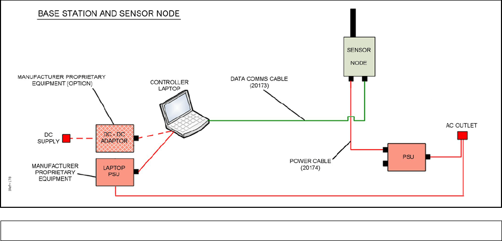
Chapter 2
Page 23
5 Position the Base Station Sensor Node in the chosen location. Make sure that the Sensor Node
is positioned as high as practical (at least 1.5 meters above ground level to achieve maximum
range). If necessary put the Sensor Node into a pouch and use this to secure the Sensor Node
into place.
6 If required, connect a mains power supply connector 1 on the Sensor Node using the supplied
power cable. See Figure 25.
Figure 25 Interconnection Diagram for Base Station Node using Battery Power
WARNING - TRIP HAZARD
WHEN THE SENSA-LINX DETECTOR NETWORKING SYSTEM IS IN
USE THERE ARE
CABLES THAT CAN CAUSE TRIP HAZARDS. ALWAYS ROUTE THE CABLES
TO
AVOID TRIPPING POSSIBILITIES FOR CROSSING PERSONNEL.
7 Using the Communications cable provided with the Base Sensor Node kit or provided as an
optional additional accessory, connect the RS232 port on the Laptop PC to connector 3 on the
Sensor Node. See Figure 25.
8 Turn on the Sensor Node by pressing and releasing the power switch on the Sensor Node. The
LEDs on the Sensor Node will now light up to indicate status. For further information on LEDs
refer to Section 2.1.4. If the correct sequence is not completed successfully obtain a
replacement Sensor Node.
9 Turn on the Laptop PC and login. Refer to local procedures for the username and password
Note: when first delivered, the C2 laptop computer will start up and operate without asking for a
username or password, however for additional security user accounts with passwords can be
set up. For more information, refer to para 3.1. If required check that the internal clock of the
Laptop PC is set to the ‘local’ time. Double click the icon on the desktop and start the C2
program.
Note: The first time the application is run the operator is presented with a blank network
configuration document. The operator must then manually add sensor nodes to reflect the
current network configuration. This configuration will be saved to disk and in future sessions,
the last open configuration will be automatically loaded. In addition, the operator always has the
choice to start from scratch with a blank configuration using ‘File -> New’ or to load some other
previously saved network configuration document using ‘File -> Open’. Once opened,
configuration can be used unmodified or changed if required. The C2 must be in the
disconnected state in order to load either a new or an existing network document. Press the
Connect button at the top of the main window (Figure 26). A dialog will appear presenting a list
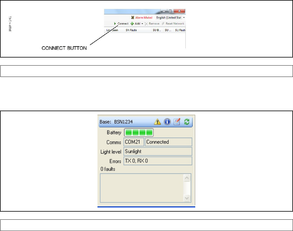
Chapter 2
Page 24
of known serial ports on the Controller PC. COM 1 is typically the comm port that will be used
though it will depend on the specific set up. For detailed information on setting up the Base
Station Sensor Node see para 2.3.1.2. The Base Station Sensor Node radio modem may be
operationally disconnected from the network by pressing the Disconnect button that replaces
the Connect button.
Figure 26 Connect Button – C2 Program Main Window
10 Confirm that the Laptop PC is now communicating with the Sensor Node by checking in the
bottom left hand of the C2 program that the status of the Base Station is now ‘Connected’ as
shown in Figure 27.
Figure 27 Base Station Sensor Node Detail Panel
11 Obtain from the storage cases the required quantity of Sensor Nodes and make a note of the
serial number of each Sensor Node. These serial numbers are marked on the identification
label of the Sensor Node.
12 In the C2 Program on the Laptop PC, use the ‘Add’ function and choose between adding a
single sensor node and adding multiple sensor nodes to the network. Enter the serial numbers
of all the Sensor Nodes that will be used at each Detector Sensor Node. The sequence in which
these numbers are added is not important but it is essential to ensure that each Sensor Node is
added to the program and appears on the screen before the Sensor Nodes are taken away to
the Detector Sensor Node locations. For further information on adding Sensor Nodes to the
network see para 3.4.3.3.
13 The Base Station Sensor Node is now setup and ready for operation. When Sensor Nodes are
set up commence operation of the Sensa-LINX Network.
14 Although the network is now ready for use, it is useful to take advantage of one or both of the
map panels as these can provide a good deal of information at a glance. Open a map panel if it
isn’t already and press the ‘Open map file’ button on the toolbar (see Figure 28).
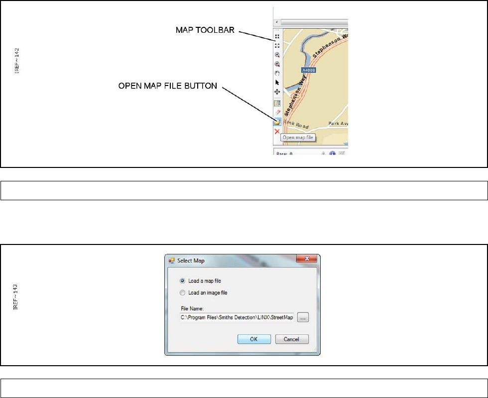
Chapter 2
Page 26
2.3.3 Sensor Node Set Up
A Sensor Node is the point at which a detector is to be setup as a node on the Sensa-LINX Detector
Networking System. Use the following information as a guide to setting up a Sensor Node for the
Sensa-LINX Detector Networking System. Equipment for this location is provided as part of the
Detector Sensor Node Kit. The detector Sensor Node set up varies slightly depending on which
detector is being used and if an external power source is to be used. There is, however, no
significant difference to the set up whether the sensor node is to be secured in a fixed location,
secured to a vehicle or worn as personal equipment. Refer to Figure 30 and Figure 31 below for
further cable and connector information.
1 At the Sensor Node the following equipment is required as a minimum:
• One LCD3.3, with Adaptor Pouch or PCA as required, or LCD Nexus detector or CAM XTR.
Detectors must have Sieve Pack(s) installed and batteries fitted.
• One Sensor Node with antenna and batteries fitted.
• One Data (Comms) cable (Detector to Sensor Node).
2 At the Sensor Node the following equipment is optional:
• Sensor Node and Detector Power Supply Unit and cables (if external power is available)
• One Sensor Node Pouch (for securing the Sensor Node in position and weather protection).
• One Detector Node Pouch (for securing the Detector in position and weather protection).
• Mounting brackets and accessories to mount the Sensor Node to the relevant sensor
WARNING – EXPOSURE TO RADIO FREQUENCY ENERGY.
THIS DEVICE TRANSMITS RADIO FREQUENCY ENERGY. WHEN WORN ON THE
BODY, ONLY THE SUPPLIED ACCESSORIES (INCLUDING THE POUCH) MAY BE
USED WITH THE EQUIPMENT AND THE EQUIPMENT MUST NOT BE CO-LOCATED
WITH OR OPERATED IN CONJUNCTION WITH ANY OTHE
R ANTENNA OR
TRANSMITTER
3 Determine where the Sensor Node is to be located taking into account factors such as terrain,
local structures and weather conditions and proximity to other Sensor Nodes. For further
information on positioning factors refer to para 3.3. If required put the Sensor Node into a pouch
and use this to secure the Sensor Node into place. If the Sensor Node is to be used in a mobile
situation (i.e. worn or carried by the operator) make sure only the correct accessories are used
and no other radio equipment is present.
WARNING - TRIP HAZARD
WHEN THE SENSA-LINX DETECTOR NETWORKING SYSTEM IS IN US
E THERE ARE
CABLES THAT CAN CAUSE TRIP HAZARDS. ALWAYS ROUTE THE CABLES
TO
AVOID TRIPPING POSSIBILITIES FOR CROSSING PERSONNEL.
CAUTION – Incorrect Connections
There are two connectors on the Sensor node. These connectors are keyed to
prevent misconnection but damage may occur if an incorrect connection is
attempted forcefully. Check that the correct connector is being used before
connection. Make connections c
arefully and do not force connection if resistance is
felt.
4 Place the LCD3.3 into the LCD 3.3 Pouch with Dock, or PCA (operator option).
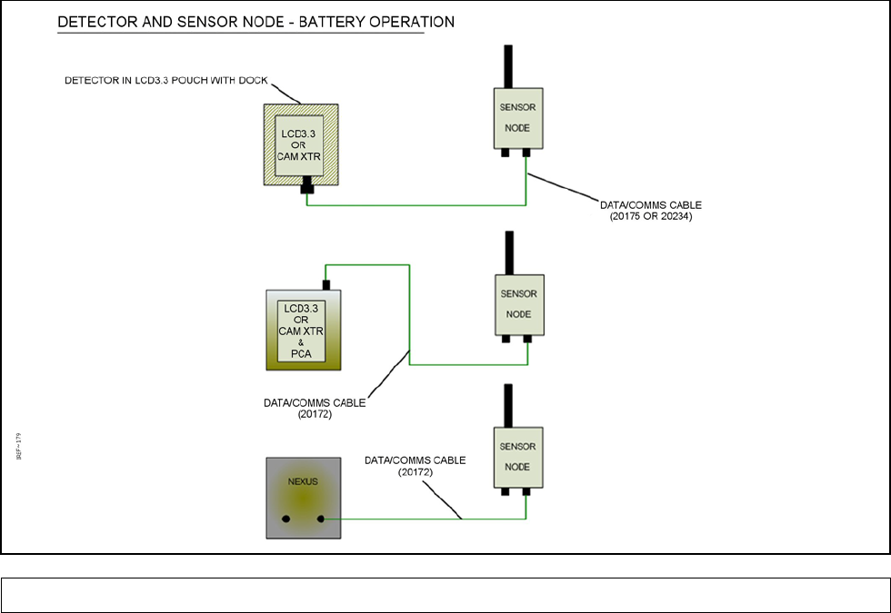
Chapter 2
Page 27
5 Position the detector (LCD3.3 NEXUS or CAM XTR) at the chosen location or use as a
personal detector and set it up for operation (refer to the appropriate section of the detector
Operators’ Manual for further information).
CAUTION – Siting of Equipment.
The Sensor Node can benefit from ‘line-of-sight’ for effective communication when
near the limits of its trans miss ion range
. If the Sensor Node is incorrectly sited,
proper communication may
not be established with its paired Sensor Node. Ensure
the Sensor Node is correctly sited.
6 Determine an appropriate location for the Sensor Node and secure in position making sure it is
at least 1.5 metres above ground level. For further information on siting Sensor Nodes refer to
para 3.3.
CAUTION – Use of Sensor Nodes in wet weather.
The Sensa-LINX Sensor Nodes and Laptop PC contain electronic components which
can be damaged by water. In heavy rainfall conditions make sure equipment battery
compartments are fully closed against water ingress and the antenna is installed to
the Sensor Node.
7 Using the appropriate Data (Comms) cable provided with the Detector Sensor Node Kit,
connect the connector on the LCD3.3 Pouch with Dock, PCA or NEXUS detector or CAM XTR
to Connector 3 on the Sensor Node. Refer to Figure 30.
Figure 30 Interconnection Diagram for the Sensor Node using Battery Power
8 If an external power supply is available and is to be used, use the PSU or DC to DC Adaptor
(see Figure 11) and relevant cable to connect an external supply to Connector 1 on the bottom
of the Sensor Node. Refer to Figure 31.
9 Start the detector. For further information refer to the manufacturer’s handbook.
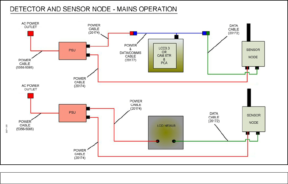
Chapter 2
Page 28
Figure 31 Interconnection Diagram for the Sensor Node using Mains Power
WARNING - RISK OF EXPLOSION
SENSOR NODES MAY PROVIDE AN IGNITION SOURCE IN AN EXPLO
SIVE
ATMOSPHERE DUE TO RF TRANSMISSIONS. DO NOT USE THE SENSOR NOD
ES IN
AN ENVIRONMENT WHERE EXPLOSIVE VAPOURS ARE PRESENT.
CAUTION - Radio Modem Frequency Band
The Sensor Nodes use a frequency band that is available for use by other
unlicensed RF devices. Such devices may interfere with the operation of the Sensor
nodes or may be interfered with by the Sensor Nodes. The Sensor Node
incorporates
features to minimise such interference but performance may be
degraded. Check the location
and frequency of other RF devices in the area before
operating the Sensor Nodes.
9.1. Turn on the Sensor Node by pressing and releasing the power switch on the Sensor
Node. The LEDs on the Sensor Node will now light up to indicate status. For further
information on LEDs refer to Section 2.1.4. If the correct sequence is not completed
successfully obtain a replacement Sensor Node.
9.2. The green Radio LED will initially be off (indicating no signals being received from the
Laptop PC location. Wait for at least 1 minute before moving the Sensor Node - the
Sensor Node may take up to this time to acquire communications with the Base Station
Sensor Node. The LED will start to pulse when a signal is being received: a single pulse
for a poor signal, a double pulse for a good signal and a triple pulse for a strong signal.
To improve the signal, if required, move the Sensor Node to either
9.2.1. a higher location.
9.2.2. a clearer line of sight.
9.2.3. a shorter range to the Base Station location.

Chapter 2
Page 29
10 When the Sensor Node has acquired radio communications, confirm at the Detector that it is
communicating with the Sensor Node (a “U” icon will appear on the display of the Detector, it
may take a few moments for this to appear).
11 Repeat set up activity for each required Sensor Node. At this stage the Sensor Node is setup.
12 Once all Sensor Nodes are setup and indicating radio signal connection, return to the Base
Station Node and check the status of the C2 program. Confirm that each Sensor Node appears
on the screen with an active status.
13 The network is now ready for use. Once connected, changes can be made to Base Station
Node, Sensor Node, and Sensor settings using the various Detail panels as described in
Section 3.4.6.
2.4 ALARMS
Figure 32 Alarm Pop-up Window
The Sensa-LINX C2 program can be configured so that when a ‘new’ alarm is received by the
Laptop PC the alarm pop-up window will be shown (Figure 32) and this must be acknowledged
using the ‘OK’ button before proceeding. Once this dialog has been acknowledged the alarm will
continue to sound but can be stopped with the ‘Silence Local Alarm’ button in the Alarms log
window. The alarm will sound again at the next detection event. The alarms log window, see para
3.4.7, will be activated automatically when a new alarm is received and the new alarm will be
highlighted. Depending on the selected system preferences the Alarm Log Window may open
automatically or may open minimised and indicated by a flashing button on the toolbar. If ATP-45
generation mode is set to manual then the ‘ATP-45’ button is enabled in the Alarms window which
allows the ATP-45 form to be launched against the selected alert; in automatic generation mode the
ATP-45 report will be generated at this point. For further information on ATP45 reports see para
3.4.2.1.
In the event of an alarm, audible alarms may be sounded at both the Controller PC and the sensor,
and the C2 program offers the opportunity to silence both. CAUTION is advised before silencing the
sensor alarm because if it has been enabled it is likely that personnel in the vicinity of the sensor
wish to exercise control over the audible alarm.
Summary of the actions possible when an alarm is received:
• Click OK on the Alarm pop-up window. This clears the visual alarm.
• Click ‘Silence Local Alarm’ in the Alarms window. This silences the alarm sound produced
by the Laptop PC.
• Click ‘Silence Sensor Alarms’ in the Alarms window or on the Sensor Panel in the main
window. This silences the alarm on the selected sensor(s).
• An operator near the alarming sensor node can also silence the alarm by pressing any
button on the keypad. This does not silence the local alarm on the Controller PC.
For further information about alarms see para 3.4.7.
Chapter 2
Page 30
2.5 LOSS OF COMMUNICATIONS.
WARNING - LOST COMMUNICATIONS
DETECTION DATA CANNOT BE TRANSMITTED IF COMMUNICATION BETWEE
N THE
SENSOR NODE AND THE BASE STATION IS INTERRUPTED OR LOST.
PROTECTION
FOR PERSONNEL MAY BE REDUCED IF ALARMS/ALERTS ARE NOT IMMEDIA
TELY
DISPLAYED AT THE BASE STATION AND SOME INFORMATION THAT IS S
TORED
WAITING FOR COMMUNICATION TO RESUME MAY BE OVERWRITTEN. MAKE
SURE
THAT COMMUNICATION BETWEEN THE SENSOR NODE AND
THE BASE STATION IS
MAINTAINED AS MUCH AS POSSIBLE AND ANY LOST COMMUNICATION IS
INVESTIGATED AND REPAIRED AS QUICKLY AS POSSIBLE.
If communication between a Sensor Node and the Base Station is lost or interrupted Alarm/Alert
messages sent by the Sensor Node will not immediately be displayed by the C2 application.
In the event of lost or interrupted communications some detection information will be stored in the
buffer memory of the Sensor Node awaiting restoration of communication. Operators should be
aware that, depending on the type and amount of detection information being gathered, the
information record may not be complete as some information may be overwritten.
When communication is restored the messages will be sent to the Base Station and will be
displayed by the C2 application as historical alarms accompanied by an indicator showing the
original time of the alarm/alert occurrence. It is expected that communications will be restored within
a reasonable timeframe however if communications are not restored, data will discarded after 90
hours from the time of storage.
2.6 SAVING NETWORK SETTINGS
The current network configuration can be saved at any time using either File>Save or File>Save As.
2.7 SHUT DOWN
2.7.1 C2 Shut Down
To exit the C2 application, choose File -> Exit or click the X in the top right corner of the main
window. The current configuration will be automatically saved to disk for use in the next session.
It is not necessary to disconnect from the network before exiting the C2 application but it does not
hurt to do so.
2.7.2 Equipment Shut Down
The Sensor Node (Radio Modem) is shut down by pressing and releasing the power switch on the
top of the unit.
When shutting down the Laptop PC, follow the procedure described for program shutdown above,
then shut down the laptop PC using the normal PC Start -> Shutdown method. For further
information refer to the manufacturer’s handbook.
For information on shutting down a detector refer to the manufacturer’s handbook.

Chapter 2
Page 31
2.8 PUTTING SENSA-LINX EQUIPMENT INTO STORAGE
CAUTION – Corrosion due to Battery Leakage
Batteries must not be left in the Sensor Node if it will not be used for a period of
time in case of leakage, which will cause corrosion. Make sure that the batteries are
removed from the Sensor Node prior to any storage period.
CAUTION – Battery Power Discharge
Batteries left in the Sensor Node
will discharge over a period of time even when the
equipment is switched off. The expected battery life may be significantly reduced if
a Sensor Node has stored containing batteries. If the Sensor Node will not be used
for a period of time, m
ake sure that the batteries are removed prior to any storage
period.
Remove all batteries when placing Sensa-LINX equipment into storage.
The Sensa-LINX equipment should be stored in a dry environment within the temperature range
also shown in TABLE 7 below.
TABLE 7. STORAGE TEMPERATURE RANGES
Radio Modem -39 °C (-38.2 °F) to 70 °C (158 °F)
Laptop PC -20 °C (-4 °F) to 60 °C (140 °F)
Chapter 2
Page 32
This page is intentionally left blank
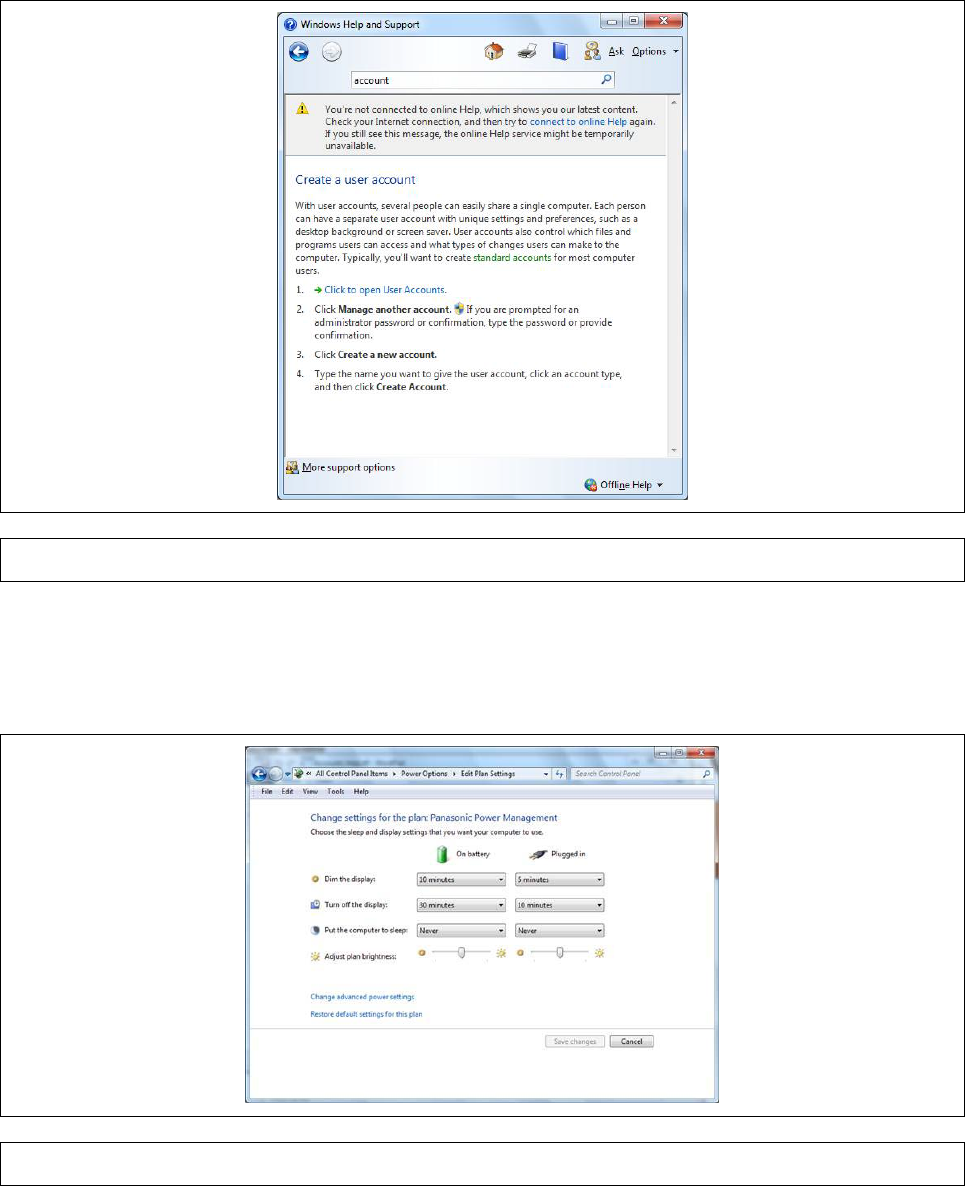
Chapter 3
Page 33
*2 CHAPTER 3 TECHNICAL DESCRIPTION
3.1 USER ACCOUNTS ON THE C2 LAPTOP OR OTHER COMPUTERS
For delivery, the C2 laptop computer is configured to start-up without asking for a username or
password. The system can be used in this configuration, however for additional security user
accounts with passwords can be added. For more information, please refer to the help files that are
installed on the computer (Go to the “Start Menu”, Select “Help and Support”, search for “account”
and select “Create a user account”, see below).
Figure 33 Windows ‘Help and Support’
If you do create new accounts (or install the C2 application on a different computer) ensure that it is
set never to “hibernate” as the system will lose communication with the Sensa-LINX network when
the computer hibernates (On Windows 7, go to “Control Panel / Power Options / Edit Plan Settings”
and set “Put the computer to sleep” to “Never” in all circumstances, see below).
Figure 34 Power Management Pop-up Window
Chapter 3
Page 34
3.2 POSITIONING FACTORS FOR THE BASE STATION NODE
The following factors should be taken into consideration when positioning the Base Station Node:
• Where possible avoid positioning the Sensor Node near metal structures and objects.
• Sensor nodes must be positioned with the antenna pointing straight up (i.e. do not lie the
sensor node down on top of another object).
• The Base Station Node must be positioned so that:
1. For a network using 868MHz hardware every Sensor Node will be within the range
limitations of the Base Sensor Node. For more information on range capabilities see TABLE 2
Radio Modem Variants
2. For a network using 900MHz or 2.4GHz hardware at least one Sensor Node will be within
the range limitations of the Base Sensor Node and any other Sensor Node is within the range
limitations of another Sensor Node (this type of sensor node can “repeat” signals to the
basestation node). For more information on range capabilities see TABLE 2 Radio Modem
Variants
• The Laptop PC should be protected from direct exposure to precipitation as the Laptop PC is
splash proof but not fully weatherproof.
• If external power is to be used the Laptop PC must be positioned within range of an AC power
outlet.
• The Base Station Sensor Node must be positioned within the cable length of the Laptop PC so
that it can be connected to the Laptop PC.
• The Base Station Sensor Node must be positioned at least 1.5 meters above ground level for
best range coverage. The higher the Sensor Node can be located, the better the network
performance will be.
• When GPS data is required the Base Station Sensor Node must be oriented with a clear view
of the sky so that a GPS signal can be located.
• If external power is to be used for the Base Station Sensor Node then the Sensor Node must
be positioned within the cable range of an AC power outlet.
3.3 POSITIONING FACTORS FOR THE SENSOR NODE
The following factors should be taken into consideration when positioning the Sensor Node:
• Sensor nodes must be positioned with the antenna pointing straight up (i.e. do not lie the
sensor node down on top of another object).
• For sensor nodes that are mobile (e.g. being worn by an operator) or when first positioning a
fixed sensor node, set the node to be “Mobile” (see Section 3.4.6.1.6). This will increase the
data rate from the sensor node so that its position and communications status is regularly
updated.
• Once a good position is located, if the sensor node is in a fixed position (i.e. not expected to
move) then it should be set using the C2 to be “Fixed” (see Section 3.4.6.1.6). This will reduce
the data update rate from that sensor, leaving more capacity for more sensors (although alarm
signals are always sent as high priority messages, regardless of this setting) and will also warn
the operator if the sensor node’s GPS position changes.
• The detector should be positioned as required to detect hazardous vapors (refer to appropriate
part of detector manual for further information)
• The Sensor Node must be positioned so that:
1. For a network using 868MHz hardware every Sensor Node will be within the range
limitations of the Base Sensor Node. For more information on range capabilities see TABLE 2
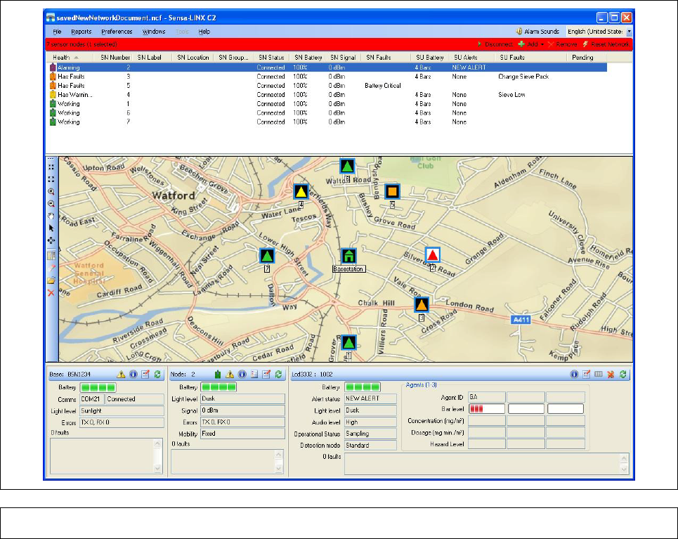
Chapter 3
Page 35
Radio Modem Variants
2. For a network using 900MHz or 2.4GHz hardware at least one Sensor Node will be within
the range limitations of the Base Sensor Node and any other Sensor Node is within the range
limitations of another Sensor Node (this type of sensor node can “repeat” signals to the
basestation node). For more information on range capabilities see TABLE 2 Radio Modem
Variants.
• The Detector Sensor Node must be positioned within the cable range of the detector.
• When GPS data is required the Detector Sensor Node must be positioned with a clear view of
the sky so that a GPS signal can be located.
• The Detector Sensor Node, when in a fixed location, must be positioned at least 1.5 meters
above ground level to prevent signal interference. If the Sensor Node is to be mobile i.e. worn
by personnel the equipment should be positioned as high as practically possible.
• Where possible avoid positioning the Sensor Node near metal structures and objects e.g.
fences, shipping containers etc.
• If external power is to be used the Sensor Node must be positioned within the cable range of
the AC power outlet.
3.4 DETAILED C2 DESCRIPTION
Following is a comprehensive description of each element of the Sensa-LINX C2 Application.
3.4.1 GUI Layout
The C2 program is based around a main window, and from this a number of other windows are
accessible. Below is an overview of the main window.
Figure 35 Sensa-LINX C2 Main Window

Chapter 3
Page 36
3.4.1.1 Title bar
The title bar displays the name of the current network configuration document as well as the
application name and the standard Windows minimize, maximize, and close buttons.
3.4.1.2 Menu bar
The menu bar houses a number of menus for managing and configuring the C2 and the network. In
addition, it allows the operator to mute local alarms and choose which language is used for the C2
display. For further information on the available menus and their functions see para 3.4.2.
3.4.1.3 Status bar
The status bar is home to four buttons for managing the state of the network: Connect/Disconnect,
Add, Remove, and Reset Network. Additionally, it provides at-a-glance health of the network by
changing to the color of the least healthy node in the network. The health colors are:
TABLE 8. HEALTH COLORS
Color
Meaning
Green
Communicating and no faults or alarms reported
Grey
Not Communicating
Yellow
Communicating but has some faults (e.g. battery low) which do not prevent operation
Orange
Communicating, but has more serious faults (e.g. sieve expired, not connected to sensor) which
may prevent the sensor or sensor node from functioning correctly or at all
Red
Agent Alarm
3.4.1.4 Sensor Node List
The sensor node list displays information about each of the sensor nodes in the network. Each line
shows an icon and indicates the status of both the sensor node and any attached sensors along with
the health of the connection to the Base Station Node and a number of other system metrics.
3.4.1.5 Map Panels
The map panels, of which there are two, allow the operator to load either a georeferenced map or an
image, such as a building schematic, and to display the BSN and SNs in the network at their
relevant locations.
• For map files, valid formats include ESRI maps (.mxd) and GeoTiffs (.tiff).
• For image files, valid formats include .bmp, .jpeg, .png, .gif and .tiff. Note: If a GeoTiff is
opened with the ‘Load an image file’ radio button enabled then it will be treated like an image
and not like a map which means nodes will not be able to be automatically placed on it.

Chapter 3
Page 37
3.4.1.6 Detail Panels
The detail panels display in depth information about the BSN as well as the selected SN(s) and
sensor(s). The panels also allow the operator to change settings, initiate Built-In-Tests, and perform
other component specific operations.
3.4.2 Menus
See TABLE 9 below for information on the available menus and their functions.
TABLE 9. C2 P ROGRAM MENUS
Level 1 Menu
Item
Level 2 Menu
Item
Description
File New*
Creates a new (blank) Network Configuration Document.
Requests confirmation of the action from the user if the
current NCD has unsaved changes.
Open* Loads an existing Network Configuration Document. Opens
an OS-
provided File Open dialog to enable the user to
choose the NCD. Requests confirmation of the action from
the user if the current NCD has unsaved changes.
Save
Saves the current Network Configuration Document.
Save As
Saves the current Network Configuration Document to a
user-specified filename. Opens an OS-
provided File save
dialog to enable the user to choose the name for the NCD.
Undo all
changes Reverts the current Network Configuration Document to its
last saved state. This feature is not available if the network is
in online mode or the configuration has not been saved.
Exit Closes the application. Requests confirmation of exit from
the user if the application is operating in online mode.
Reports ATP-45 Report Opens the ATP-45 Report generation dialog. See Section
3.4.2.1 for details.
Manual ATP-45 Sets the ATP-45 report generation mode to manual. The
operator will have to manually generate a report when an
alarm occurs. See Section 3.4.2.1 for details.
Automatic ATP-
45 Sets the ATP-45 report generation mode to automatic. A
report will automatically
be generated and saved to disk
when an alarm occurs.
Preferences Folder Options Opens the Folder Options dialog. See Section 3.4.2.2 for
details.
System
Preferences
Opens the System Preferences dialog. See Section 3.4.2.3
for details.
Map Label
Choices The next four entries in the Preferences allow the operator to
choose what is used as the base station node and sensor
node labels on the map panels. The choices are:
• Label map nodes with no labels – Don’t show a label.
• Label map nodes with SN label – Use the sensor
node’s label as its label on the map.
• Label map nodes with SN Serial Number – Use the
sensor node’s serial number as its label on the map.
• Label map nodes with SN Group Location

Chapter 3
Page 38
TABLE 9. C2 P ROGRAM MENUS
Map Group
Coloring
Choices
Map group colouring choices
The next three entries in the Preferences menu allow the
operator to choose how the sensor nodes on the map are
highlighted in terms of group locations.
• Highlight no groups – Don’t do any group specific
highlighting
• Highlight all groups – Highlight each group of nodes
in a different colour.
• Highlight the selected group – Highlight only those
nodes in the same group as the node currently
selected.
Windows
Alarms
Displays the Alarms window
Warnings
Displays the Warnings window
Events
Displays the Events window
Show Details
Panels
Toggle item. Enables or disables display of the BSN, SN and
sensor details panes
Show Map 1 Toggle item. Enables or disables display of the
first map
window
Show Map 2 Toggle item. Enables or disables display of the second map
window
Tools Sensa-LINX
NCT
If the NCT is installed then the Tools menu will be enabled
and contain an item that will launch the NCT from the C2.
Help Operators
Manual
Displays the C2 application operators manual in another
window (using Adobe Reader or an equivalent package if
installed). The Operators Manual will be in the currently
selected language
Map Icons
Legend
Displays the Map Icons Legend window. See Section
3.4.2.4 for details.
About
Displays application version information in an about box
* Denotes menu options only available when the C2 is in Offline mode
3.4.2.1 ATP-45 Report Dialog
ATP 45 reports may be automatically generated against any alarm event detected (from the alarms
window); however it is also possible to manually generate an ATP-45 report, which launches the
ATP-45 window with no default fields apart from the date and time. This window is opened from the
Reports menu item on the main window toolbar.
CAUTION – inaccurate contamination spread prediction
In ATP -
45 reports the “height” field will default to zero (this field represents the
height above ground level, not altitude, and this cannot be ac
quired from the GPS).
This may give inaccurate results if used to predict the spread of contamination
when the sensor is positioned at a significant height above ground level (e.g. on a
tall building). If using ATP-45 reports to predict contamination spread; either
position sensors at ground level, or set the ATP-45 mode to ‘Manual ATP-45’ and
edit the “height” field to a realistic value.
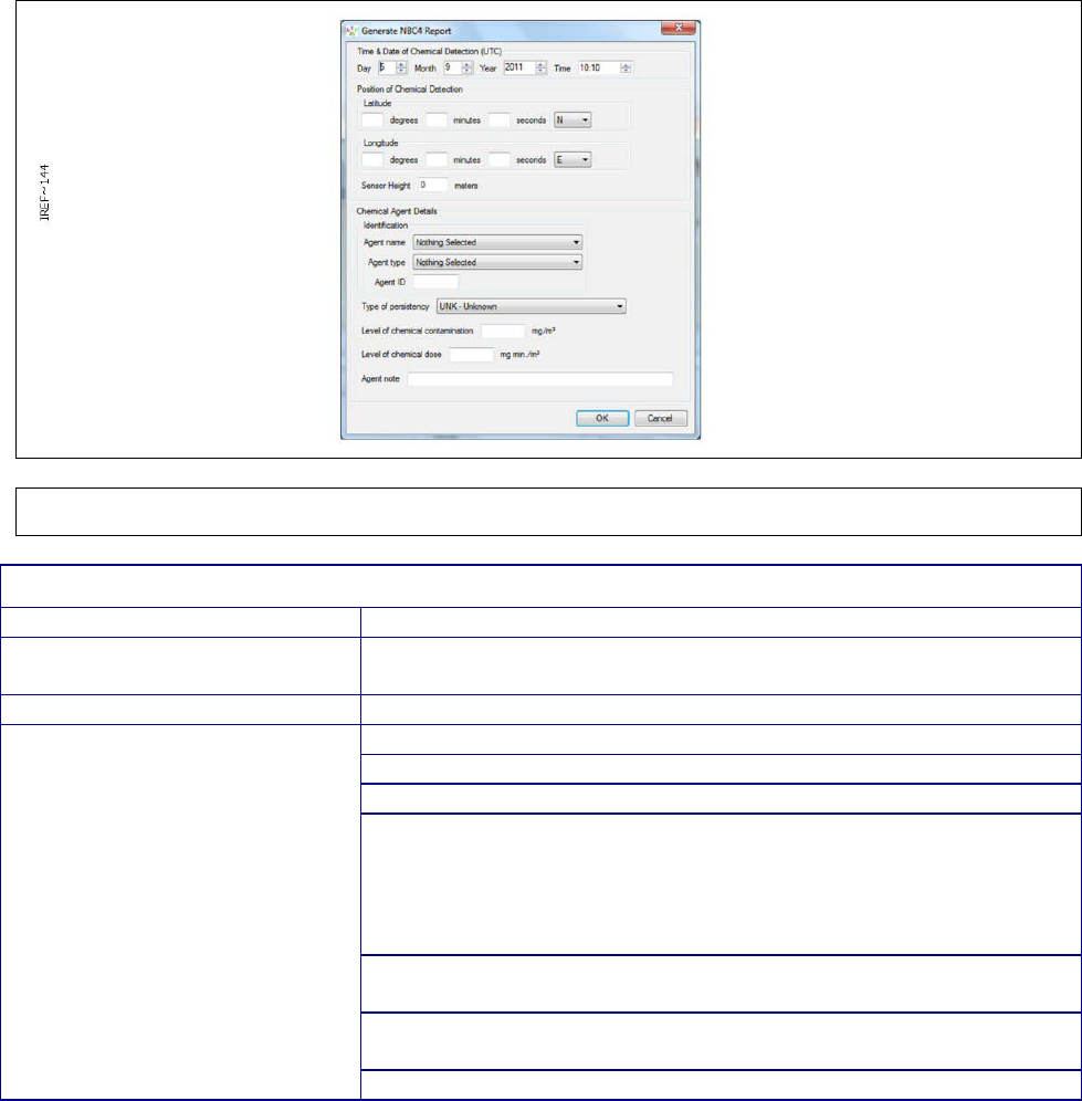
Chapter 3
Page 39
The fields ‘Time & Date’, Position (Lat/Long), Sensor Height (above ground level) are mandatory
(although the default sensor height of zero is an acceptable value). One of ‘Agent Name’, ‘Agent
Type’ or ‘Agent ID’ is also mandatory. All other fields are optional. If a mandatory field is not filled
when the user presses ‘OK’, a pop up window will remind the operator to enter required data.
ATP-45 reporting has two configurable modes – ‘Manual ATP-45’ mode and ‘Automatic ATP-45’
mode, selectable via the Reports menu and saved as preference for each user. In ‘Automatic Mode’
an ATP-45 report is generated for each ‘new’ alarm event (i.e. when a sensor transitions between
not alarming and alarming) but not for new information about the same alarm. In ‘Manual Mode’ a
single Alarm record must be highlighted to access the ATP-45 menu, the ATP-45 reports are
generated by the operator from a button on the Alarms window (see 3.4.7); no attempt is made to
ensure that an ATP-45 report is filed.
The Date & Time of Chemical Detection, Latitude and Longitude and most Chemical Agent Detail
fields are automatically filled in but can be manually filled or changed by the Operator.
If a known agent is detected, then the ‘Agent Name’ field will be populated; otherwise the ‘Agent
Type’ field will be populated.
Figure 36 ATP-45 Report Dialog
TABLE 10. ATP-45 REPORT DIALOG FIELDS
Field Name
Contents
Date & Time of Chemical
Detection
Date/Time in UTC
Position of Chemical Detection
Latitude, longitude, and height of the sensor at time of detection
Chemical Agent Details
Agent name - Name of the chemical agent detected
Agent type - Type of chemical agent detected
Agent ID - ID of the chemical agent detected
Type of persistency. Valid values are:
Non-Persistent
Persistent
Thickened
Unknown
Level of chemical contamination - Concentration by volume of
the detected substance.
Level of chemical dose. Dosage information for the detected
substance.
Agent note - Operator defined note
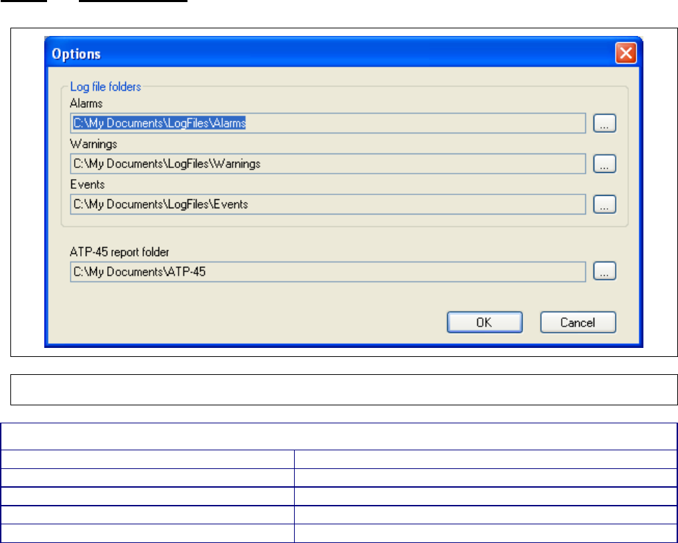
Chapter 3
Page 40
3.4.2.2 Folder Options
Figure 37 Folder Options Dialog
TABLE 11. FOLDER OPTIONS DIALOG FIELDS
Field Name
Contents
Alarms
Location to which the alarms log files will be written
Warnings
Location to which the warnings log files will be written
Events
Location to which the events log files will be written
ATP-45 report folder
Location to which the ATP-45 reports will be written
Storage locations for log files may be changed by the user. Clicking on the ellipsis button opens a
new dialog that allows the user to browse for the preferred storage location. Clicking the OK button
in each case will change and then save the preferred storage location
Note: In Windows 7 the default path will display as:
C:\Users\<user name\Documents\...
when you actually go to navigate to this directory the Documents folder is called ‘My Documents’ so
the actual path is:
C:\Users\<user name\My Documents\...
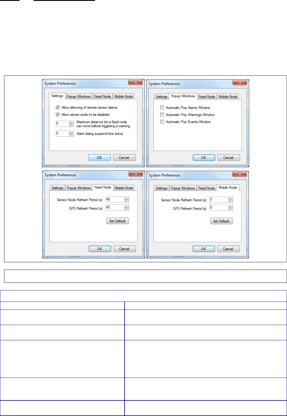
Chapter 3
Page 41
3.4.2.3 System Preferences
CAUTION – Reduced System Performance
Changing t
he Sensor Node Refresh Period and GPS Refresh Period can adversely
affect the performance of the Sensa-LINX system.
Setting the refresh rate too high
may result in system overload whereas setting the refresh rat
e too low may result in
lost data or non-current data being displayed. Take care if changing the refresh
rates
from their default settings (40 seconds for fixed nodes and 5 seconds for
mobile nodes). Revert to the default settings if issues occur.
Figure 38 System Preferences Dialog
TABLE 12. SYSTEM PREFERENCES DIALOG FIELDS
Field Name
Contents
Allow silencing of remote alarms
Controls whether the operator is able to silence
alarms on the sensor themselves from the C2.
Allow sensor audio to be disabled Cont
rols whether the operator is able to silence
alarms on the Laptop PC through the C2.
Maximum distance (m) a fixed node can
move before triggering a warning
Movement of a sensor node with mobility set as
‘Fixed’ triggers a warning in the system. This option
allows the operator to set the distance that the node
must move before the warning is generated. This is
useful in situations where some GPS drift may occur.
Alarm dialog suspend time (mins) The amount of time that an Alarm event window will
be suspended when the “Do not display for x minutes”
is selected by the operator (see Section 2.4).
Automatic Popup Alarms Window
When selected, new alarms (or changes in alarm
status) will cause the alarms log window to open
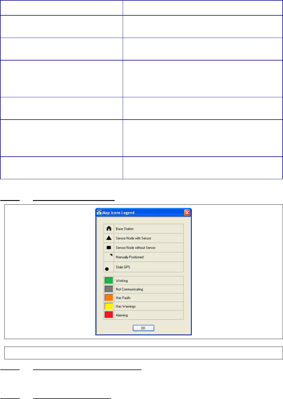
Chapter 3
Page 42
automatically in front of the main window (but behind
any alarm indication).
Automatic Popup Warnings Window
When selected, new warnings (or changes in warning
status) will cause the warnings log window to open
automatically in front of the main window.
Automatic Popup Events Window
When selected, new events will cause the events
window to open automatically in front of the main
window.
Fixed Node:
Sensor Node Refresh Period
The rate at which routine data will be reported from
the sensor node to the basestation for a node marked
as “Fixed” (see Section 3.4.6.1.6).
Note: alarm messages are always sent immediately,
regardless of this setting.
Fixed Node:
GPS Refresh Period
The rate at which GPS data will be reported from the
sensor node to the basestation for a node marked as
“Fixed” (see Section 3.4.6.1.6).
Mobile Node:
Sensor Node Refresh Period
The rate at which routine data will be reported from
the sensor node to the basestation for a node marked
as “Mobile” (see Section 3.4.6.1.6).
Note: alarm messages are always sent immediately,
regardless of this setting.
Mobile Node:
GPS Refresh Period
The rate at which GPS data will be reported from the
sensor node to the basestation for a node marked as
“Mobile” (see Section 3.4.6.1.6).
3.4.2.4 Map Icons Legend Window
Figure 39 Map Icons Legend Window
3.4.2.5 Alarm Sounds / Alarm Muted button
Allows the operator to prevent the audible alarm on the PC from sounding when an alarm is raised.
3.4.2.6 Language selection menu
Allows the operator to change the language in which the application is displayed at run-time.
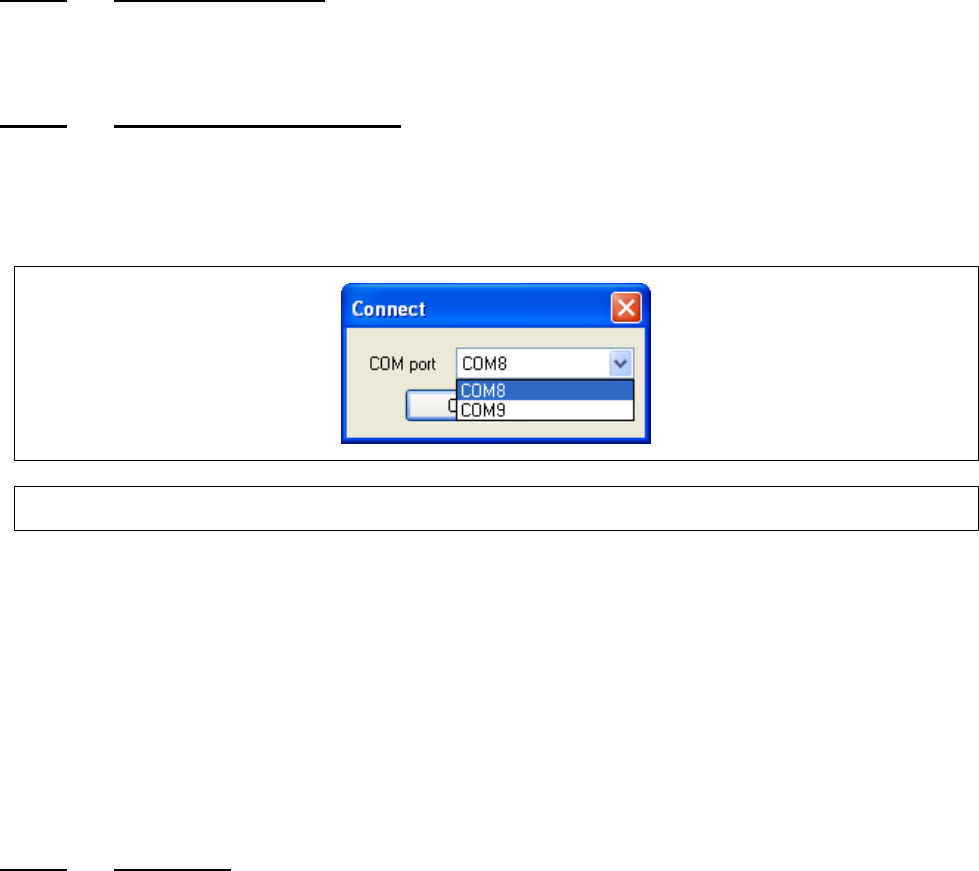
Chapter 3
Page 43
3.4.3 Status bar
In addition to the information described below. The status bar indicates the health status of the least
healthy node in the network by changing to one of the five health colors. (for further information on
Health Colours see TABLE 8)
3.4.3.1 Sensor node counts
The left portion of the status bar displays a count of how many sensor nodes are in the network and
how many are currently selected in the C2.
3.4.3.2 Connect/Disconnect button
Used to toggle between Offline and Online modes. When toggling to Online mode, a Connect dialog
is displayed which lets the operator select which COM port the C2 should use to connect to the base
station node. The Panasonic Toughbook CF31 that is supplied when requested has only one COM
port.
Figure 40 Connect Dialog
3.4.3.2.1 Connectivity Modes
The C2 is always considered to be in one of two modes: Offline or Online. It is in Offline mode any
time it is not trying to connect or currently connected to a Base Station Node. The significance of
these modes is that various fields throughout the application will either display current information or
last known information depending on the mode.
The mode of the C2 can be determined by looking at the Connect/Disconnect button in the status
bar. In Offline mode the button will say ‘Connect’ and in Online mode the button will say
‘Disconnect’.
3.4.3.3 Add button
The Add button drops down a menu with two choices: Add single sensor node and Add multiple
sensor nodes
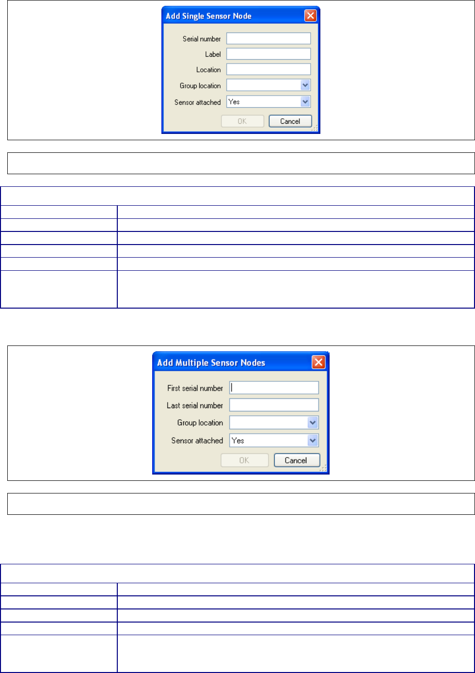
Chapter 3
Page 44
3.4.3.3.1 Add Single Sensor Node Dialog
Figure 41 Add Single Sensor Node Dialog
TABLE 13. ADD SINGLE SENSOR NODE DIALOG FIELDS
Field Name
Contents
Serial Number
Sensor Node Serial Number (as shown on SN Label)
Label
Operator defined label
Location
Operator defined location
Group location
Operator defined group location
Sensor Attached Whether or not this sensor node has an attached sensor (a Sensor Node
without an attached detector may be used to repeat a radio signal from
more distant /less accessible Sensor Nodes)
3.4.3.3.2 Add Multiple Sensor Nodes Dialog
Figure 42 Add multiple Sensor Nodes Dialog
This dialog allows the operator to add multiple sensor nodes at the same time as long as they have
consecutive serial numbers.
TABLE 14. ADD MULTIPLE SENSOR NODES DIALOG FIELDS
Field Name
Contents
First serial number
Serial number of the first sensor node in the group to be added
Last serial number
Serial number of the last sensor node in the group to be added
Group location
Operator defined group location
Sensor Attached
Whether or not these sensor nodes have attached sensors (Sensor
Nodes without an attached detector may be used to repeat a radio signal
from more distant /less accessible Sensor Nodes)
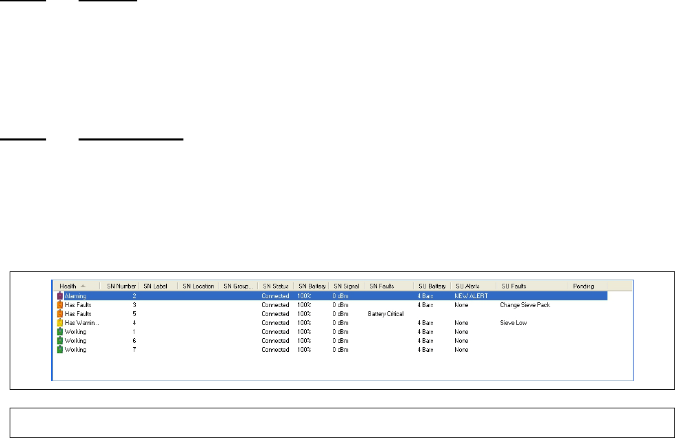
Chapter 3
Page 45
TIP: The serial number of a Sensor Node can be acquired by connecting to the base station node
and waiting for warnings to come in indicating that unknown sensor nodes are attempting to join the
network. The serial numbers of these sensor nodes will be presented in the warning and can then
be entered in to either of the Add Sensor dialogs. This method works equally well for single (para
3.4.3.3.1) or multiple (para 3.4.3.3.2) sensor nodes to be added to a network.
• For single sensor node addition, the sensor node serial number and the attached sensor
fields are required, and the other fields are provided so the operator can add useful
information for interpretation in the main window and the alarms, warnings, and events
windows.
• The attached sensor field is used by the C2 to determine whether the sensor node should
have a sensor attached. This is used by the C2 to prevent false ‘missing sensor node’
warnings when a sensor node is being used simply as a network relay.
• For multiple sensor node addition, the first and last serial numbers in a sequential list of
serial numbers can be entered and the sensor attached state must be set. In addition it is
possible for the operator to define a common Group Location for the new sensor nodes.
Note: The Label, Location, Group location fields are provided as a means for the operator to
identify and categorize the sensor nodes in the network in a way that makes sense for their
particular application.
3.4.3.4 Remove
The ‘Remove’ button removes the selected sensor nodes from the network after operator
confirmation. To remove one or more sensor nodes from an existing network, select the node(s) in
either a map panel or in the sensor node list and press the Remove button at the top of the main
window and confirm when requested. The C2 will no longer communicate with the removed sensor
nodes unless they are added back to the network.
3.4.3.5 Reset Network
Performs an automatic disconnect and reconnect of the network.
The operator does not normally need to use the Reset button but it is available if the network fails to
respond.
3.4.4 Sensor Node List
Figure 43 Sensor Node List
The sensor node list displays information about each of the sensor nodes in the network. Each line
shows a colored icon indicating the health of the connection and/or sensor node, along with a
number of status items for both the sensor node and the attached sensor.
Note: Fault/Warning/Alarm coloring is maintained even when a device stops communicating
and thus an icon referring to a Sensor Node with a fault will NOT turn grey if communication
stops.

Chapter 3
Page 46
The list can be sorted by any of these status items by clicking on the corresponding column title. In
addition, the columns can be resized and reordered. If the columns do not all fit on the screen then
a horizontal scroll bar will appear at the bottom of the sensor node list.
If there are more Sensor Nodes than can be displayed in the list at once then a vertical scroll bar will
appear.
Selecting Sensor Nodes in the C2 is mentioned for a variety of operations and can be achieved in a
number of ways. Single Sensor Nodes can be selected by either clicking on their entry in the
Sensor Node list or clicking on their icons in the map area of a map panel.
Multiple Sensor Nodes can be selected by holding CTRL and clicking on the desired Sensor Node’s
entries in the Sensor Node list or on their icons in the map area of a map panel. It is also possible to
select multiple Sensor Nodes at once by holding SHIFT, clicking on an entry in the Sensor Node list
and then clicking on another entry farther down the list. Both the clicked on Sensor Nodes and all
the ones in between will be selected.
TABLE 15. STATUS ITEMS
Column Name
Contents
Health A health status for the sensor node/sensor pair. The health status indicator
includes a coloured icon that gives a visual indication to the health of the
item(s).
SN Number Serial number
SN Label* Operator defined label
SN Location* Operator defined location
SN Group Location* Operator defined group location
SN Status Comms status
SN Battery Charge percentage of the SN battery
SN Signal Signal strength
SN Faults Fault indication for the SN
SU Battery Battery bars indication for the attached sensor
SU Alerts Alert status for the attached sensor
SU Faults List of faults on the attached sensor
Pending List of pending changes for the sensor node and its attached sensor unit.
* Denotes fields that can be defined when the sensor node is added to the network document as
mentioned above and also through the sensor node detail panel as described below
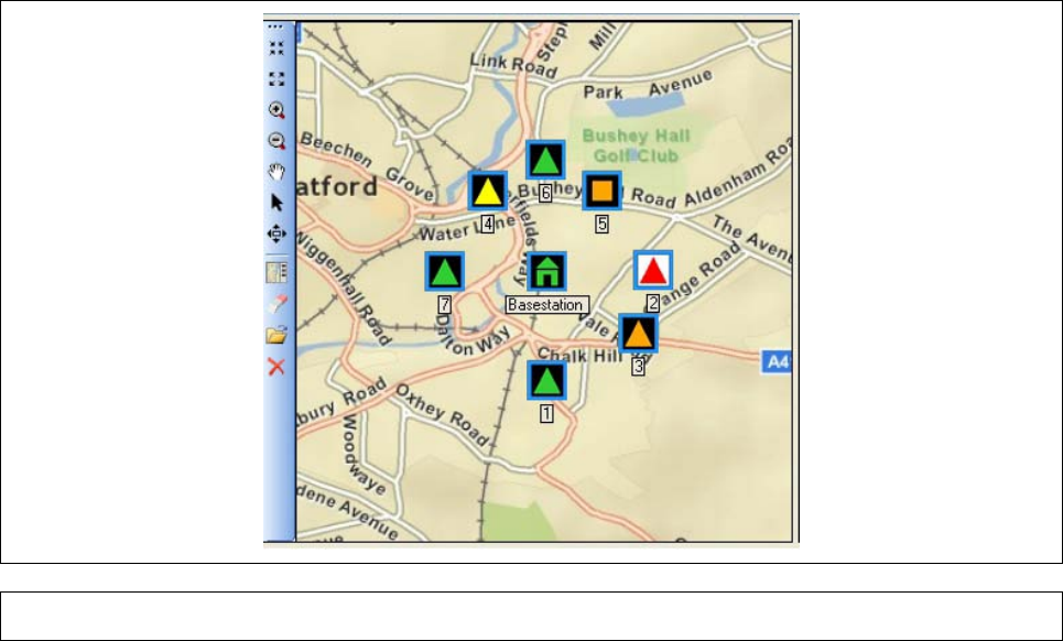
Chapter 3
Page 47
3.4.5 Ma p s
Figure 44 Map Panel
The map panel allows the operator to load either a georeferenced map or an image, such as a
building schematic. It is then possible to display the sensor nodes in the network at their relevant
locations.
If a map file was loaded, a decision is required as to whether the Sensor Node locations should be
positioned automatically using GPS data or if they should be positioned manually. Manual
positioning will override the GPS data in the C2 program and may affect things like the data shown
in the alarms window and data in the ATP-45 reports.
Nothing further is required for automatically positioned Sensor Nodes. They will be sited at the
proper location on the map as soon as the C2 receives their position.
For manually placed nodes on both a map and an image, open the icon panel and drag the nodes
from there onto the map/image.
On a map, it is possible to toggle between the two positioning modes for a sensor node by right-
clicking on the sensor-node on the map and toggling the value in the resulting context menu. The
positioning mode may also be changed using the BSN settings dialog. See Section 3.4.6.1.2.
The map panel is composed of a toolbar, a map area, and an icon panel that can be optionally
shown or hidden. The toolbar contains the following buttons:

Chapter 3
Page 48
TABLE 16. MAP TOOLBAR ITEMS
Tool Name Action
Zoom In Zooms in on the displayed map/image by a fixed amount
Zoom Out Zooms out on the displayed map/image by a fixed amount
Zoom in and center
Places the cursor in Zoom In mode and will zoom in and center on the
clicked position of the map/image
Zoom out and
center Places the cursor in Zoom Out mode and will zoom out and center on the
clicked position of the map/image
Pan
Places the cursor in pane mode which allows the operator to pan the
map/image by clicking and dragging on the map area
Deselect map tools Returns to the arrow cursor
Set
Automatic/Manual
extent mode
Toggles the extent mode of the map con
trol.
In automatic extent the bounds of the map changes as needed to ensure
that the BSN and all of the SNs on the map/image are visible at all times.
Manual extent mode leaves it to the operator to choose the map/image
bounds.
Show/Hide Icon
Panel Toggles the icon panel
Remove all sensors Removes all nodes from the map/image and places them back in the icon
panel.
Note: In Online mode, any nodes in automatic placement mode will return to
the map/image on their next GPS position update.
Open map file Launches the Select Map dialog from which a map or image file can be
loaded into the map area.
Close map control Hides the map panel.
To show the panel again, use the Windows menu.
The map area displays the open map/image along with the BSN and SNs. It also facilitates operator
interaction with the BSN and SNs in the form of tooltips and the ability to reposition the BSN and
SNs by clicking and dragging them to new location.
TIP: In addition to the zoom tools mentioned above, it is also possible to zoom in and out using the
scroll wheel on the mouse and to zoom in by holding CTRL, right-clicking and dragging on the
map/image. This will define the map’s bounding box when you let up on the mouse button.
The icon panel contains the BSN and SNs when not displayed on the map. This is most often used
in conjunction with an image and it is where the operator acquires the BSN and SNs to be placed in
the map area.
The icons used for the BSN and SNs convey information about their state such as their type, health,
and positioning mode. The map legend accessible through the ‘Help -> Map Icons Legend’ gives a
more detailed overview of the icons. In addition, the tooltip for each icon displays more detailed
BSN and SN information such as serial number, position, positioning mode, etc. Finally, right
clicking on the BSN or a SN brings up a context menu which allows you to toggle its positioning
mode.
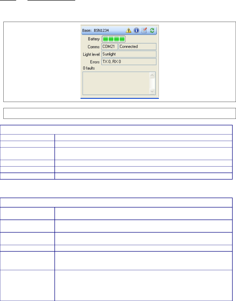
Chapter 3
Page 49
3.4.6 Detail Panels
The Detail Panels are three separate panels; the Base Station Panel (Section 3.4.6.1) the Sensor
Node Panel (Section 3.4.6.1.3) and the Sensor Panel (Section 3.4.6.2).
3.4.6.1 Base Station Panel
Shows details on the status of the BSN. The BSN serial number is displayed in the title bar of the
panel and the rest of the details are displayed below.
Figure 45 Base Station Panel
TABLE 17. BASE STATION P ANEL FIELDS
Field Name
Contents
Battery indicator
Shows the charge level of the battery
Comms
Shows the name of the COM port on the C2 PC which is used to connect
to the BSN.
Light level
The configured light level of the LEDs on the BSN.
Errors
The total number of transmit and receive errors reported by the BSN.
Faults
This field shows a list of current faults reported by the BSN.
In addition to displaying detailed information, the Base Station panel contains a toolbar.
TABLE 18. BASE STATION P ANEL TOOLBAR ITEMS
Field Name
(from left to right)
Contents
Identifier
The identifier will show “Base:“ followed by the serial number of the BSN.
In Offline mode, ‘0’ will be displayed.
BIT (Button)
Invokes a Built-In Test on the BSN. This function is not available in offline
mode.
Info (Button)
Opens the Base Station Information window (see section 3.4.6.1.1)
Settings (Button)
Opens the Base Station Settings dialog (see section 3.4.6.1.2) where
the frequency and light level settings of the BSN can be set. In Offline
mode, this button is greyed out.
Refresh (Button)
Forces the C2 application to request status and settings information from
the base station node.
The application will request confirmation from the user before proceeding
with the action.
In Offline mode, this button is greyed out.
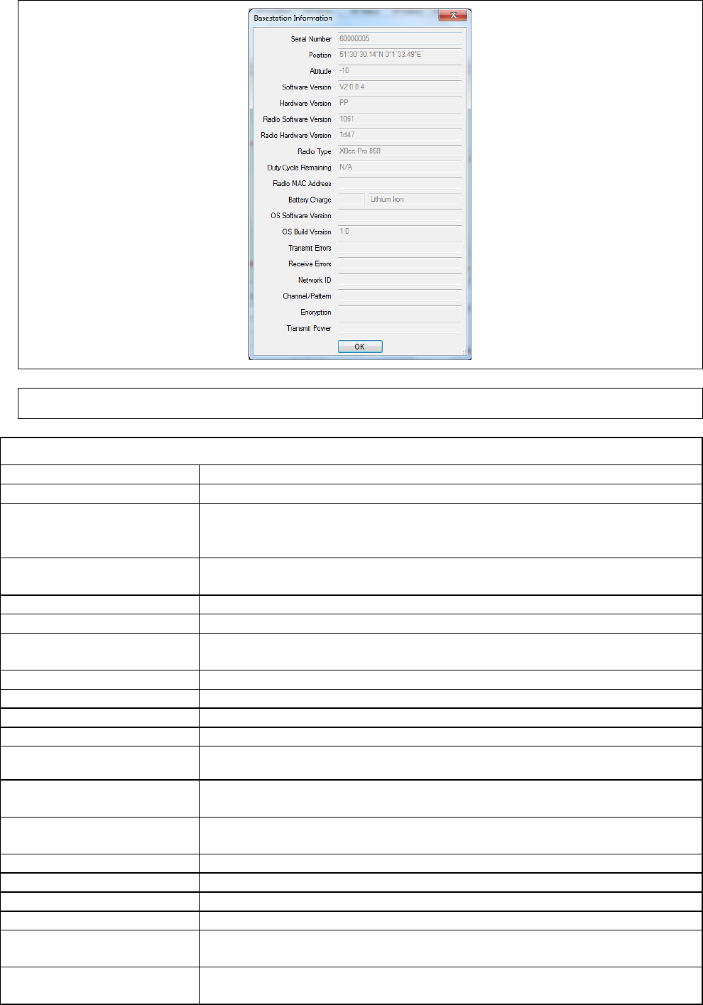
Chapter 3
Page 50
3.4.6.1.1 Base Station Information Window
Figure 46 Base Station Information Window
TABLE 19. BAS E S TATION INFORMATION WINDOW FIELDS
Field Name
Contents
Sensor node number
The serial number of the BSN
Position
Either the GPS or manual position of the BSN depending on its
positioning mode in DMS format. Note: Field is greyed out when data
is stale. “(M)” is appended when BSN is in manual positioning mode.
Altitude
Height above mean sea level in meters of the BSN. Note: Field is
greyed out when data is stale.
Software Version
The version of the Smiths application software operating on the BSN
Hardware Version
The hardware version of the BSN
Radio Software Version
The software version of the Digi software operating on the radio
module within the sensor node
Radio Hardware Version
The hardware version of the Digi radio module within the sensor node
Radio Type
The type of the Digi radio module within the sensor node
Radio MAC Address
The MAC address of the Digi radio module within the sensor node
Battery Charge
Charge level for the BSN battery and the battery type
Duty Cycle Remaining
Only shown for 868MHz radio modules: the percentage of the permitted radio
duty cycle that is remaining for use.
OS Software Version
The version of the Operating System running on the single board
computer within the BSN
OS Build Version
Build Information of the Operating System running on the single board
computer with the BSN
Transmit Errors
The number of transmission errors reported by the BSN
Receive Errors
The number of receive errors reported by the BSN
Network ID
The Digi Network ID (reported in hexadecimal)
Channel/Pattern
The radio channel or hopping pattern being used (where applicable)
Encryption The encryption settings of the sensor node – can report AES128,
FIPS, AES128 & FIPS or none.
Transmit Power
The transmission power setting of the Digi radio module – reported in
both dBm and in milliwatts
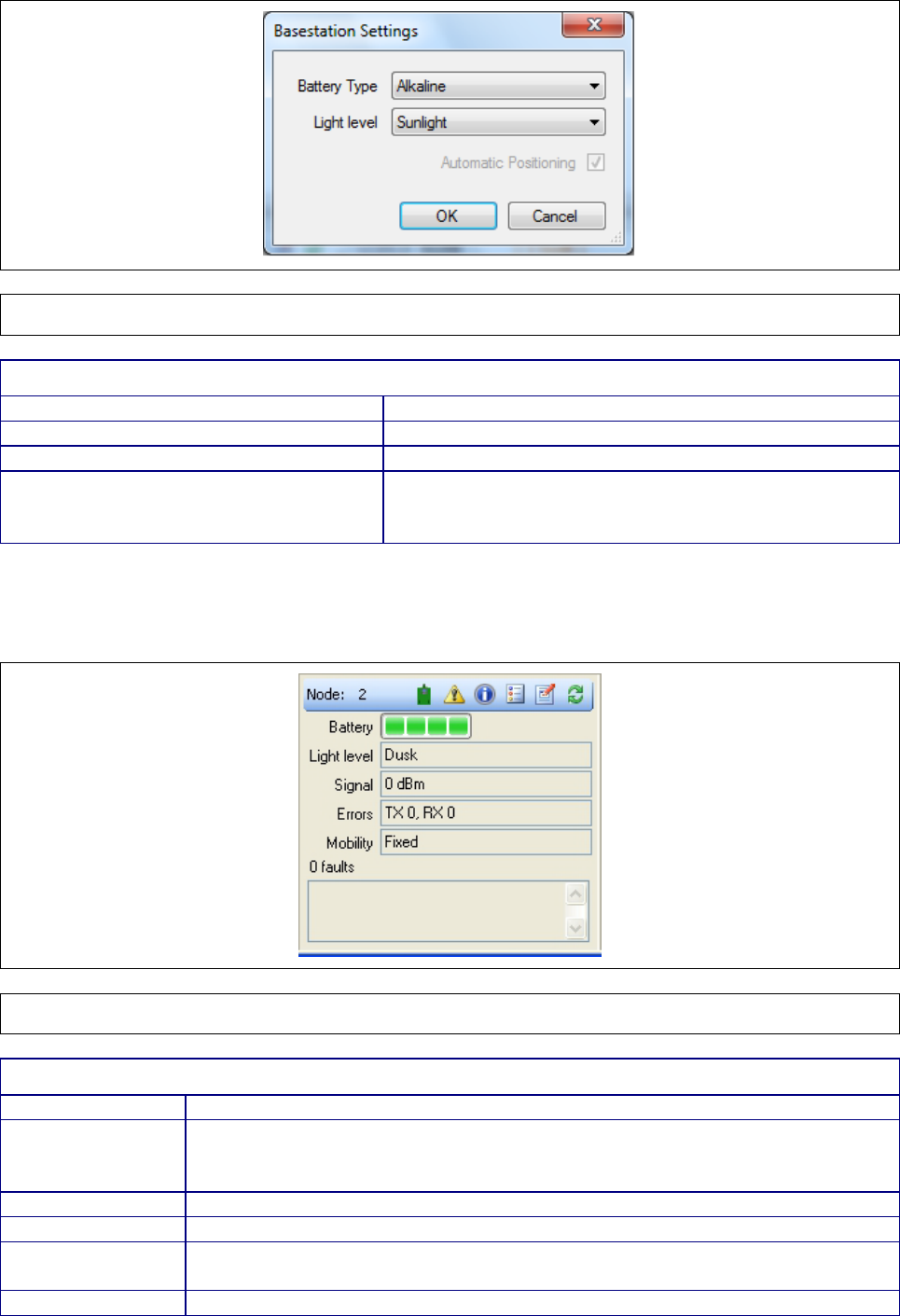
Chapter 3
Page 51
3.4.6.1.2 Base Station Settings Dialog
Figure 47 Base Station Settings Dialog
TABLE 20. BASE STATION SETTINGS DIALOG FIELDS
Field Name
Contents
Battery Type
Type of battery in the BSN.
Light level
Brightness of the BSN display.
Automatic Positioning
If BSN is set to manual positioning mode, allows
changing to automatic positioning mode. See section
3.4.5 for setting positioning mode on maps.
Sensor Node Panel
Displays detailed information about the selected sensor node(s). If more than one sensor node (SN)
is selected then each field will either display the common value or ‘Various’ otherwise.
Figure 48 Sensor Node Panel
TABLE 21. SENSOR NODE PANEL FIELDS
Field Name
Contents
Battery indicator
Shows the charge level of the battery/batteries. If the sensor node is using
an AC Mains power supply the battery ‘bars’ will be replaced with a solid
green rectangle overlaid with a gold-coloured ‘lightning’ symbol.
Light level
The configured light level of the LEDs on the SN(s).
Signal
The received signal strength in dBm as reported by the SN(s)
Errors The total number of transmit (TX) and receive (RX) errors reported by the
SN(s).
Mobility
Whether the SN(s) is/are expected to move (Mobile) or not (Fixed).
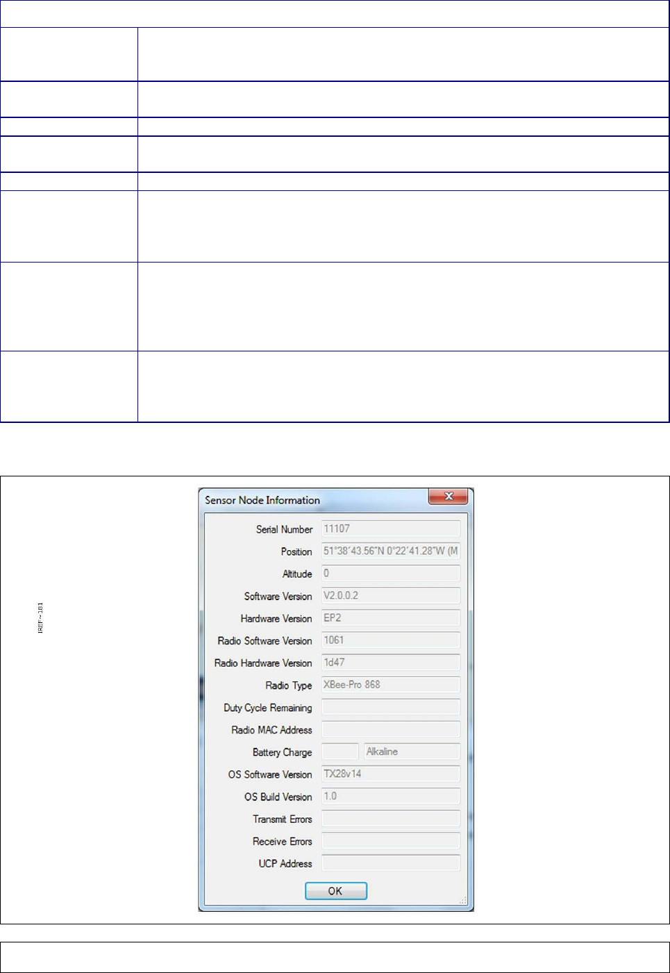
Chapter 3
Page 52
In addition to displaying information, the sensor node panel contains a toolbar.
TABLE 22. SENSOR NODE PANEL TOOLBAR ITEMS
Field Name
(from left to
right)
Contents
Identifier
The identifier will show “Node:“ followed by the serial number of the SN. If
multiple SNs are selected then it will display ‘Various’
Attached Sensor
Allows the operator to set whether the SN should have an attached sensor.
BIT (Button)
Invokes a Built-In Test on the SN. This button is only enabled when a single
SN is selected.
Info (Button)
Opens the Sensor Node Information Window (see Section 3.4.6.1.3)
Tags (Button)
Opens the Sensor Node Tags dialog (see Section 3.4.6.1.4) where Label,
Loc
ation and Group Location of the SN can be set if a single SN is selected.
Otherwise it opens the Multiple Sensor Node Tags Dialog where only the
Group Location can be set.
Settings (Button)
If a single SN is selected it opens the Sensor Node Remote Settings
dialog (see Section 3.4.6.1.6) where the light level, mobility, and battery type
of the SN can be set. Otherwise it opens the Multiple Sensor Node Remote
Settings (see Section 3.4.6.1.6) where the same settings can be set but the
serial number is not displayed. In Offline mode, this button is greyed out.
Refresh (Button) Forces the C2 application to request status and settings information from
the SN.
The application will request confirmation from the user before proceeding
with the action.
3.4.6.1.3 Sensor Node Information Window
Figure 49 Sensor Node Information Window
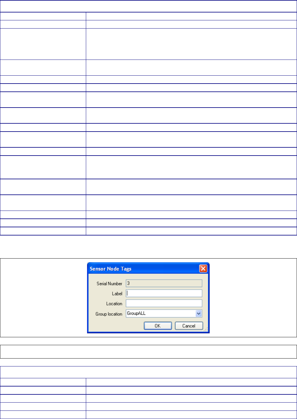
Chapter 3
Page 53
TABLE 23. SENSOR NODE INFORMATION WINDOW FIELDS
Field Name
Contents
Sensor node number
The serial number of the SN
Position
Either the GPS or manual position of the SN depending on its
positioning mode in DMS format. Note: Field is greyed out when
data is stale. “(M)” is appended when SN is in manual positioning
mode.
Altitude
Height above mean sea level in meters. Note: Field is greyed out
when data is stale.
Software Version
The version of the Smiths application software operating on the SN
Hardware Version
The hardware version of the SN
Radio Software Version
The software version of the Digi software operating on the radio
module within the sensor node
Radio Hardware Version
The hardware version of the Digi radio module within the sensor
node
Radio Type
The type of the Digi radio module within the sensor node
Duty Cycle Remaining
Only shown for 868MHz radio modules: the percentage of the
permitted radio duty cycle that is remaining for use.
Radio MAC Address
The MAC address of the Digi radio module within the sensor node
Battery Charge
Charge level for the SN battery and the battery type. If the sensor
node is using an AC Mains power supply the percentage charge field
will show ‘EXT’
OS Software Version
The version of the OS running on the single board computer within
the BSN
OS Build Version
Build Information of the OS running on the single board computer
with the SN
Transmit Errors
The number of transmission errors reported by the SN
Receive Errors
The number of receive errors reported by the SN
UCP Address
Internal network number assigned to the SN.
3.4.6.1.4 Sensor Node Tags Dialog
Figure 50 Sensor Node Tags Dialog
TABLE 24. SENSOR NODE TAGS DIALOG FIELDS
Field Name
Contents
Serial Number
Sensor Node Serial Number
Label
Operator defined label
Location
Operator defined location
Group location
Operator defined group location
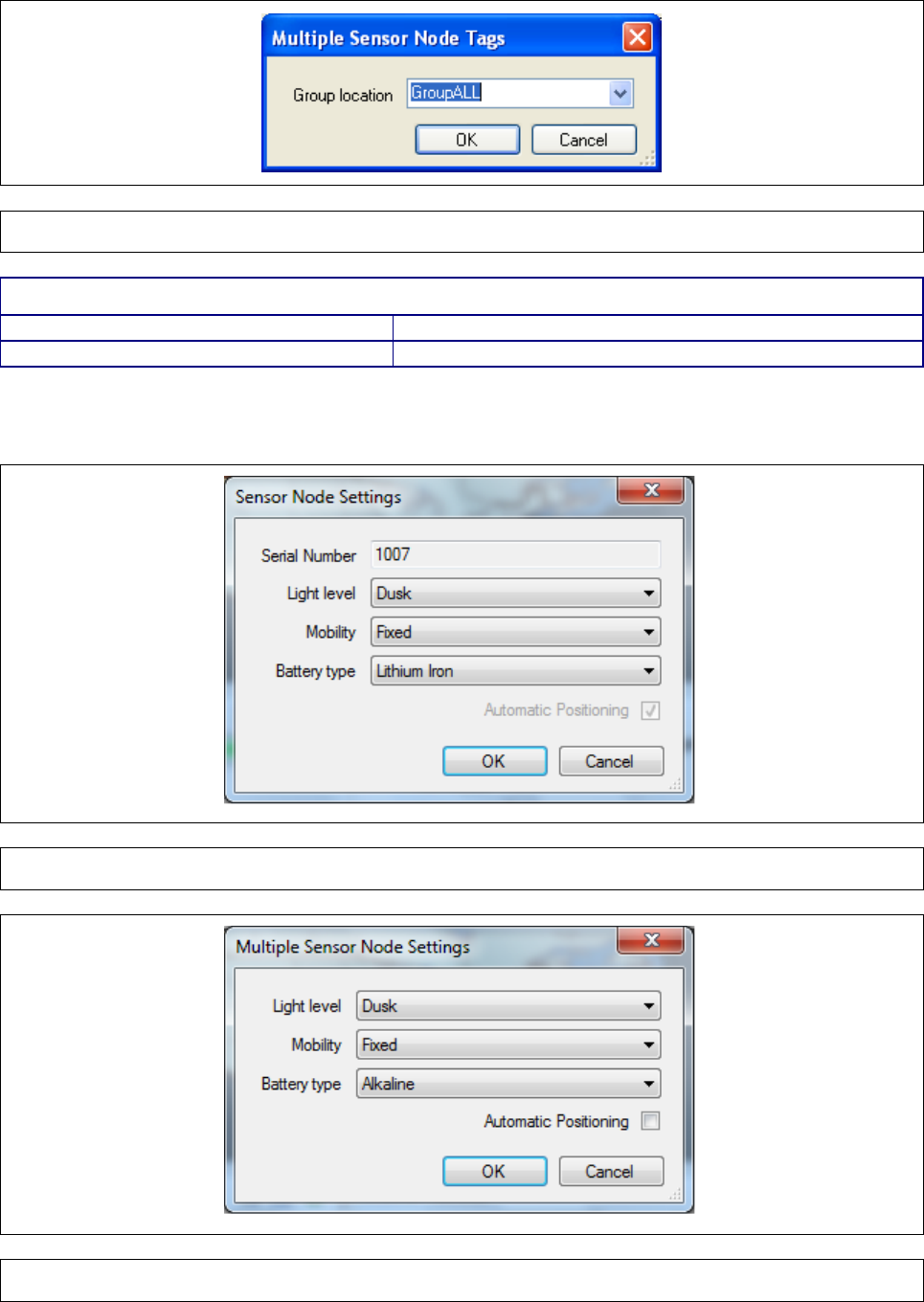
Chapter 3
Page 54
3.4.6.1.5 Multiple Sensor Node Tags Dialog
Figure 51 Multiple Sensor Node Tags Dialog
TABLE 25. MULTIPLE SENSOR NODE TAGS DIALOG FIELDS
Field Name
Contents
Group location
Operator defined group location
3.4.6.1.6 Sensor Node Settings Dialog / Multiple Sensor Node Remote Settings Dialog
Figure 52 Sensor Node Settings Dialog
Figure 53 Multiple Sensor Node Settings Dialog
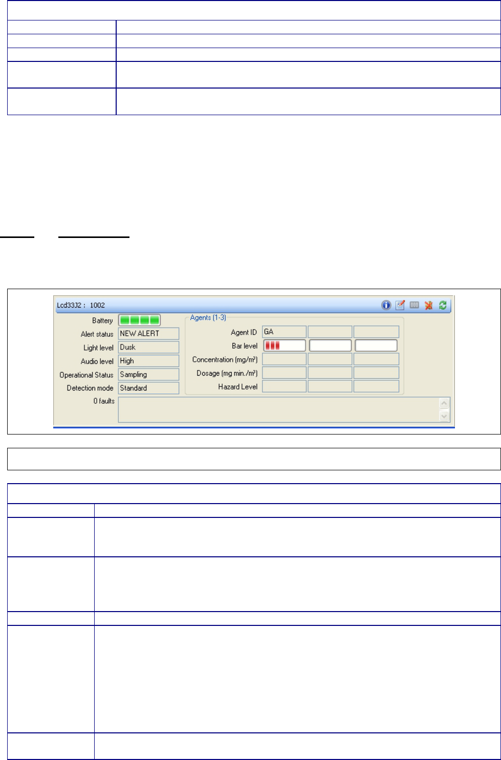
Chapter 3
Page 55
TABLE 26. SENSOR NODE REMOTE SETTINGS DIALOG FIELDS
Field Name
Contents
Light level
Set the brightness of the LEDs on the SN(s).
Mobility
Set whether the SN(s) is/are expected to move (Mobile) or not (Fixed).
Battery Type
Set the type of battery in the SN(s). This setting is used by the SN to
determine when a battery low warning should be issued.
Automatic
Positioning
If SN is set to manual positioning mode, allows changing to automatic
positioning mode. See section 3.4.5 for setting positioning mode on maps.
Sensor node settings may be changed individually or as a group. For individual changes select only
that sensor node and press the Settings button in Sensor Node panel.
To change the settings of multiple sensor nodes, select all of the relevant sensor nodes in a map
panel or in the sensor node list and press the same Settings button as used for single sensor node
changes.
3.4.6.2 Sensor Panel
Displays detailed information about the attached sensors of the selected sensor node(s). If there is
more than one attached sensor then each field will display the common value or ‘Various’ otherwise.
The title bar displays the sensor serial number or ‘Various’ if there are multiple selected sensors.
Figure 54 Sensor Panel
TABLE 27. SENSOR PANEL FIELDS
Field Name
Contents
Battery
indicator
Shows the charge level of the battery/batteries. If the sensor is using an AC
Mains power supply the battery ‘bars’ will be replaced with a solid green
rectangle overlaid with a gold-coloured ‘lightning’ symbol.
Alert status
Alert status – Indicates the alarm status of the sensor. Possible values are:
• NEW Alert
• Acknowledged
•
None
Light level
The configured light level of the LED’s on the sensor.
Audio level
Displays the current audio setting of the sensor. Possible Values are:
• High
• Medium
• Low
• Off*
*This will only be displayed if the System Preferences “Allow sensor audio to
be disabled” option is enabled or the audio level of the selected sensor(s) is
already off
Operational
Status
Displays the current operation status of the sensor(s). Possible values vary
according to sensor type but typically include:

Chapter 3
Page 56
• Sampling
• Wait
•
Major Fault
Detection
mode
Displays the current detection mode of the sensor. Values vary according to
the sensor type
Agents
If only one sensor is selected, displays information about up to three detected
agents, otherwise, these fields are blank.
Agent ID – Type of toxic chemical substance detected by the sensor using an
internationally recognized code
Bar Level – Measure of the degree of danger posed by the detected
substance. Higher bar levels imply a higher degree of danger. Bar levels are
related to the current level of concentration of the detected substance.
Concentration – Concentration of the agent measure in mg/m3
Dosage – The measure of accumulated quantity detected since power on of
the sensor. Note: Dosage information is not supported by all sensor types.
Hazard Level – Measure of the danger posed by the accumulated dosage of
the agent. Note: Hazard level information is not supported by all sensor types.
Faults
This field shows a list of current faults reported by the BSN.
In addition to displaying information, the sensor panel contains a toolbar.
TABLE 28. SENSOR PANEL TOOLBAR ITEMS
Field Name
(from left to
right)
Contents
Identifier
The identifier will show sensor type (i.e. “LCD3.3” or “Nexus”) followed by
the serial number of the sensor. If multiple sensors are selected then it will
display ‘Various’
Info (Button)
Launches the Sensor Information Window. See Section 3.4.6.2.1 for
details.
Settings (Button)
It opens the Sensor Settings dialog (see section 3.4.6.2.2) where detection
mode, audio level, backlight and keyguard can be set.
In Offline mode, this button is greyed out.
Reset Dosage
Counters (Button)
Resets the accumulated dosage information on sensors that support this.
Caution: refer to the manual for the sensor before using this control.
In Offline mode, no serial number will be displayed.
Silence Alarm
(Button)
Silence the sensor(s) audible alarm. In Offline mode this function is not
available.
Refresh (Button)
Forces the C2 application to request status and settings information from
the sensor.
The application will request confirmation from the user before proceeding
with the action.
3.4.6.2.1 Sensor Information Window
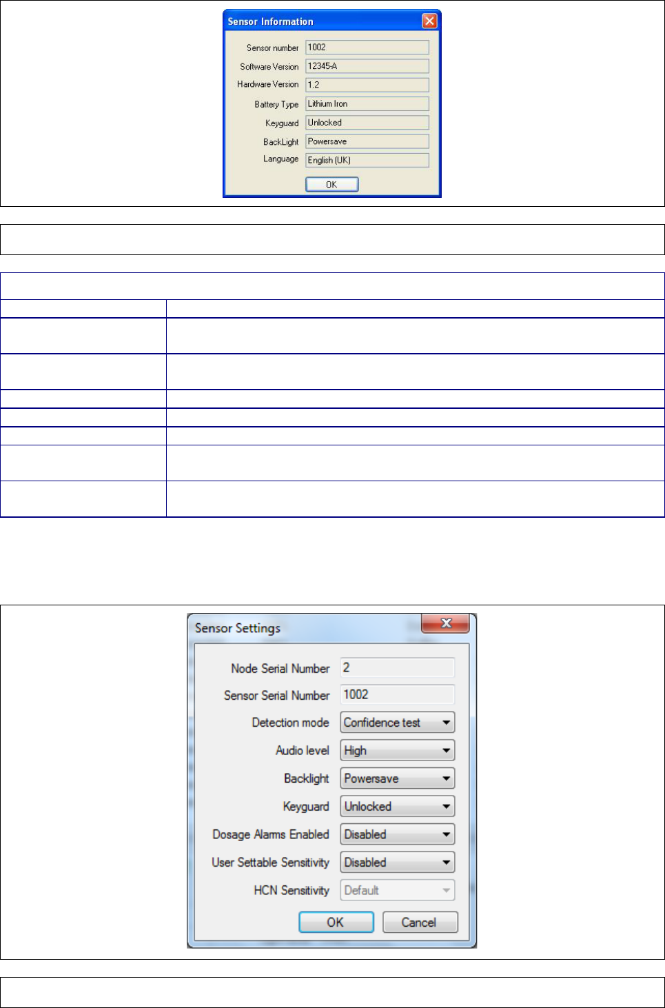
Chapter 3
Page 57
Figure 55 Sensor Information Window
TABLE 29. SENSOR INFORMATION WINDOW FIELDS
Field Name
Contents
Serial number
The serial number of the sensor. This field is omitted when multiple
Sensor Nodes are selected.
Software Version
The version of the Smiths application software operating on the
sensor(s)
Hardware Version
The hardware version of the sensor(s)
Battery Type
Type of battery / batteries in the sensor(s)
Keyguard
State of the key guard on the sensor(s). Can be locked or unlocked.
BackLight
Mode of the backlight on the sensor(s). Can be continuous or
powersave mode.
Language
Language setting for information displayed on the sensor. Note: Not all
sensor types display this information.
3.4.6.2.2 Sensor Settings Dialog
If a single sensor is selected then the dialog looks like:
Figure 56 Sensor Settings
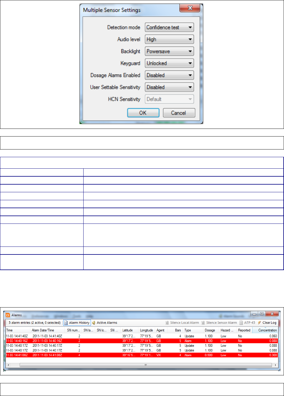
Chapter 3
Page 58
If multiple sensors are selected then the dialog looks like:
Figure 57 Sensor Settings (Multiple Sensors)
TABLE 30. SENSOR SETTINGS DIALOG FIELDS
Field Name
Contents
Node serial number*
The serial number of the sensor node this sensor is attached to
Sensor number*
Sensor serial number
Detection mode
Detection mode
Audio level
The audio level of the sensor alarms
Backlight
Backlight mode.
Keyguard
State of the keyguard.
Dosage Alarms Enabled
Set to whether dosage alarms are enabled or disabled. Note:
Dosage information is not supported by all sensor types. Dosage
alarm must be enabled on sensor to use this setting.
User Settable Sensitivity
State of sensitivity
HCN Sensitivity
Set the HCN sensitivity. This field is accessible when User Settable
Sensitivity field is set to ‘Enabled’
* Denotes fields only shown in the dialog when a single sensor is selected.
3.4.7 Alarms Log window
Figure 58 Alarms Window – Alarms History
The Alarms Log window displays details of alarms that have occurred on sensors attached to the
network.

Chapter 3
Page 59
By default, when a new alarm is received by the C2, the alarms log window is opened automatically
and the new alarm is highlighted. Note: This window behaviour can be modified from the System
Preferences window. See Section 3.4.2.3 for further details.
The Alarms Log window can also be launched manually from the Windows menu.
The Alarms Log window is composed of a status bar and a detailed listing of alarm events.
The list can be switched between two distinct modes
• Alarm History mode where a list of all alarm events that have occurred since the C2 was
started are displayed
• Active Alarms mode where a list of current (active) alarms is presented
Switching between the two modes is achieved by pressing the appropriate button on the status bar
of the Alarms Log window.
The status bar displays summary information about the alarms list, buttons to change the mode of
display, and further buttons to perform specific alarm-related functions.
The summary information comprises counts of alarm events, the currently active alarms and
selected alarms.
In addition to the mode selecting buttons, the status bar contains four buttons:
• Silence Local Alarm – Silences the audible alarm on the computer running the C2
• Silence Sensor Alarm – Silences the audible alarm on the sensor itself
• ATP-45 – Opens the Generate ATP-45 Report dialog
• Clear Log – Clears the list of displayed alarms and begins a new Alarms log file on disk.
The detailed alarms list is comprised of columns of information that can be reordered, resized and
used to sort the list of alarms. These columns include:
TABLE 31. ALARM LOG WINDOW COLUMNS
Column Name
Contents
Date/Time
The date and time at which the alarm was received by the C2
Alarm Date/Time
The date and time at which the alarm was generated
SN Number
Serial number of the SN attached to an alarming detector
SN label
Operator defined label
SN Location
Operator defined location
SN Group Location
Operator defined group location
Latitude
The Latitude of the detector at the time the alarm occurred
Longitude
The Longitude of the detector at the time the alarm occurred
Agent
Agent that triggered the alarm
Bars
Measure of the degree of danger posed by the detected substance. Higher
bar levels imply a higher degree of danger. Bar levels are related the current
level of concentration of the detected substance.
Concentration
Concentration of the detected agent
Dosage
The measure of accumulated quantity detected since power on of the
sensor. Note: Dosage information is not supported by all sensor types.
Hazard Level
Measure of the danger posed by the accumulated dosage of the agent.
Note: Hazard level information is not supported by all sensor types.
Reported
Indicates whether an ATP-45 report has been generated for this alarm entry
Type
Indicates whether an entry in the alarms log is a new alarm, update to an
existing alarm, or the clearance of a previous alarm condition Alarm events
that occur prior to the Sensor Node joining the network,
or while
communications were not possible between the Sensor Node and the C2,
are marked with ‘(H)’ to denote a historical alarm.
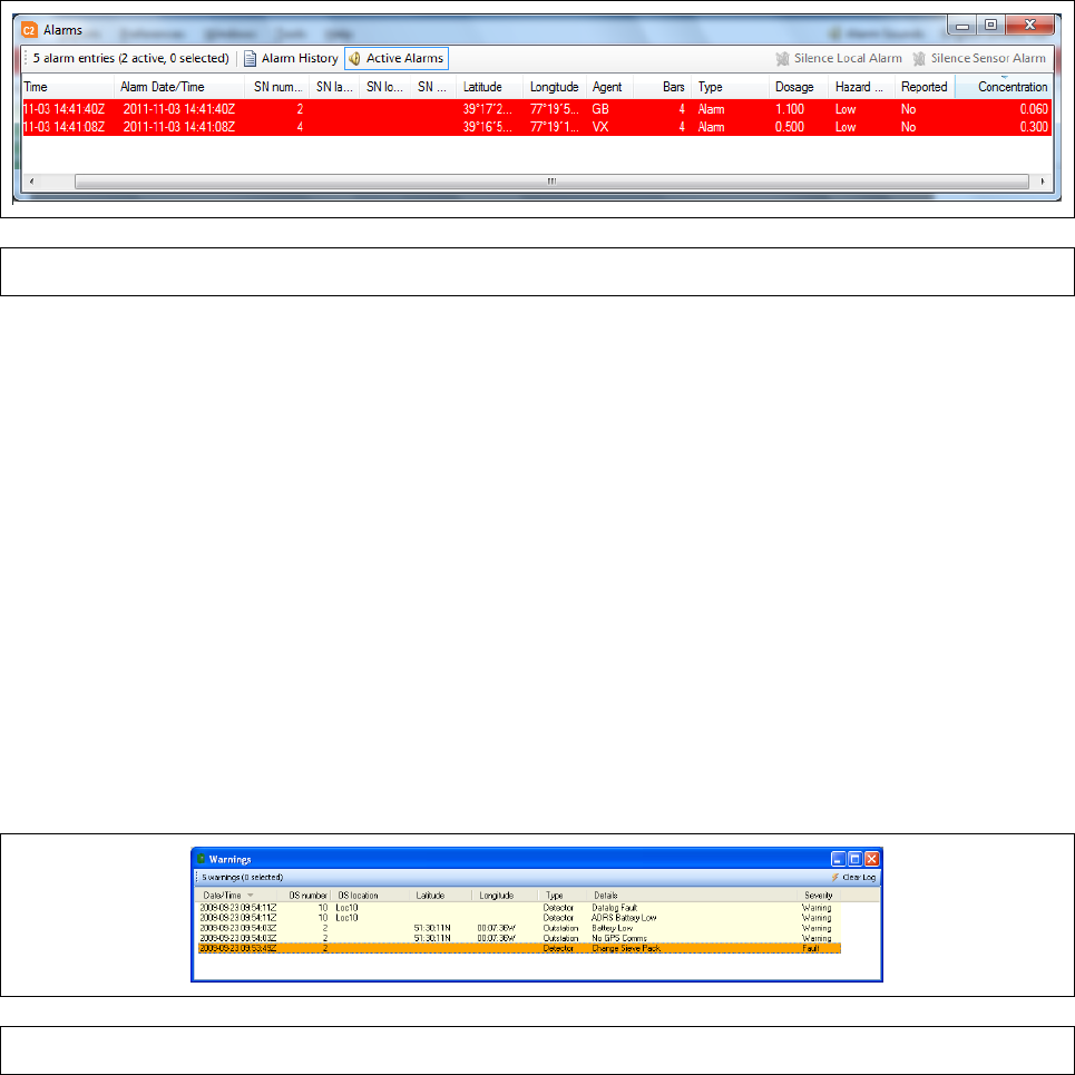
Chapter 3
Page 60
When a new alarm is above threshold (typically 3 bars) or has dosage information is received, the
alarm is listed in ‘Alarms History’ tab and in ‘Active Alarms’ tab. If the new alarm is below threshold
or has no dosage information, the alarm is only listed under ‘Alarms History’ tab. If an existing alarm
increases or decreases in reading whilst staying in alarm, (say 3 bars up to 4 bars) then a new line is
generated in the ‘Alarms History’ tab but the new line is not highlighted and the existing entry in
‘Active Alarms’ tab is updated. If a different sensor reports an alarm, then a new line is added to
‘Alarms History’ tab and ‘Active Alarms’ tab and the line is highlighted. This ‘highlighting’ will be
different from selection so it will be possible to select one of the highlighted alerts and to make an
ATP-45 report based on its data. These alarm events are automatically saved to log files on disk
with a unique filename in all of the supported languages, but a restart of the program creates a new
log file.
Figure 59 Alarms Window – Active Alarms
When multiple lines are selected, it will not be possible to perform ATP-45 reporting as each event
must be reported separately but the ‘Silence Sensor Alarm’ option will still be enabled so that
multiple alarms can be silenced in one operation; this brings up the ’Silence Multiple Alarms’ dialog.
If a detection condition drops below the alarm threshold and has no dosage information then the
Sensor Unit audible alarms will stop (the Controller PC alarm will continue to sound until the ‘Silence
Local Alarm’ menu option in the Alarms window is pressed) the alarm event is removed from the
‘Active Alarms’ tab and the active alarm count on the status bar is reduced. It will still be possible to
generate an ATP-45 report from the line in question. If the window has been sorted according to a
different criteria from the default (decreasing timestamp) then if an alarm is raised no attempt will be
made to change this. This may result in an alarm being highlighted but invisible to the operator, but
the window will still be brought to the front.
Refer to sensor Operators Manual for further information on sensor set up and alarm generation.
3.4.8 Warnings window
Figure 60 Warnings Window
Displays detailed information about warnings generated by the base station node, the sensor nodes,
or the C2 itself. The Warnings window is composed of a status bar and a detailed warnings list.
The status bar displays the total number of warnings in the list and how many are currently selected.
In addition it contains a Clear Log button that clears the warnings list in the C2 and starts a new
Warnings log file on disk.
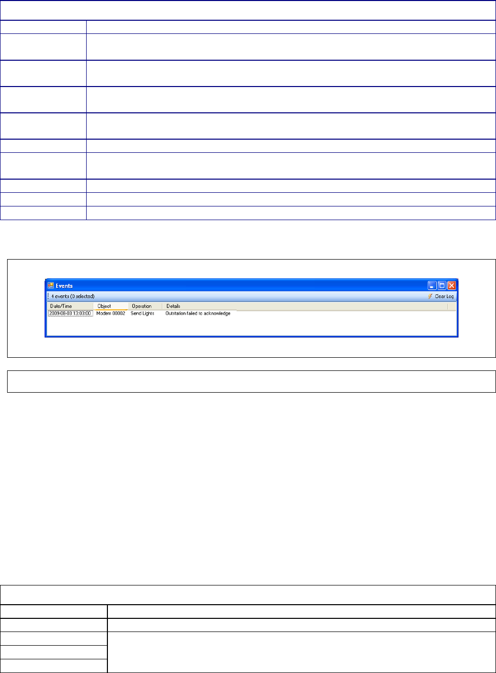
Chapter 3
Page 61
The detailed warnings list is comprised of columns of information that can be reordered, resized and
used to sort the list of alarms. These columns include:
TABLE 32. WARNING WINDOW COLUMNS
Column Name
Contents
Date/Time
Date/time the warning was generated. May be blank if no data has been
generated.
SN Number
Serial number of the BSN or SN that generated the warning if this warning came
from the BSN or a SN May be blank if no data has been generated.
SN Location
Operator defined location of the sensor node associated with the warning (if any)
May be blank if no data has been generated.
SN Group
Location
Operator defined group location of the sensor node associated with the warning
(if any) May be blank if no data has been generated.
Latitude
Latitude of the BSN or SN associated with the warning (if any)
Longitude
Longitude of the SN attached to an alarming detector. May be blank if no data
has been generated.
Type
The source of warning. Can be Network, Base Station, Sensor Node or Sensor.
Details
The text of the warning
Severity
The severity of the warning.
3.4.9 Events window
Figure 61 Events Window
Displays detailed information about events generated by the network and software diagnostic
information. This includes failing to receive acknowledgement messages in a timely fashion, loss of
communications and internal timeouts. These events are intended as a diagnostic aid for engineers
so the contents will only be logged in English.
The Events window is composed of a status bar and a detailed events list.
The status bar displays the total number of events in the list and how many are currently selected.
In addition, the status bar contains a Clear Log button that clears the events list and starts a new
Events log file on disk.
The detailed events list is comprised of columns of information that can be reordered, resized and
used to sort the list of alarms. These columns include:
TABLE 33. EVENT WINDOW COLUMNS
Column Name
Contents
Date/Time
Date and time the event was generated
Object
These columns display technical information related to the particular event
that occurred.
Operation
Details
Chapter 3
Page 62
This page is intentionally left blank
Chapter 4
Page 63
*3
CHAPTER 4 INSTALLATION INFORMATION
4.1 SENSA-LINX SOFTWARE INSTALL AND UNINSTALL
4.2 SENSA-LINX C2 AND NCT INSTALLATION
The Sensa-LINX C2 (Command and Control) and NCT (Network Configuration Tool) applications
are installed to the Controller PC. The following information is provided if it is necessary to install
these applications to a laptop PC or a workstation that does not already have them installed.
Requirements:
• Operating System: Microsoft Windows XP (32-bit editions) with Service Pack 3 or
later, Microsoft Windows Vista (32-bit editions) with Service Pack 2 or later, or
Microsoft Windows 7 (32 or 64-bit editions) with Service Pack 1 or later
• Microsoft .NET Framework 3.5 with Service Pack 1 or later
• ArcGIS Engine Runtime 10.0 with Service Pack and Internet Tiled Maps Patch
• To use some NCT functions you will require Windows Mobile Media Center (on
Windows Vista or Windows 7) or Microsoft ActiveSync (on Windows XP) – see
section APPENDIX A for details
NOTE – Administrative privileges are required for installation
The install CD will contain:
• Operating Instructions for Panasonic Toughbook CF-31 ruggedized laptop
• ESRI ArcGIS Engine Runtime 10.0 Installer
• ESRI ArcGIS Engine Runtime SP2 Installer
• ESRI ArcGIS Engine Runtime SP2 Internet Tiled Maps Patch
• Sensa-LINX Installer (includes the C2 and NCT applications)
• Freescale Manufacturing Tool – Used by the NCT to update the sensor node
firmware
• Adobe Reader – This is provided as a convenience to the user as an electronic copy
of the operator’s manual will be provided in PDF format.
The install order of the software should be:
• .NET Framework 3.5 with Service Pack 1 (obtainable from Microsoft – this may
already be installed on your computer)
• ESRI ArcGIS Engine Runtime
(located at CDDrive:\ESRI\EngineRT\setup.exe)
• ESRI ArcGIS Engine Runtime SP2
(located at CDDrive:\ESRI\ArcGISEngine10sp2.msp)
• ESRI ArcGIS Engine Runtime SP2 Internet Tiled Maps Patch
(located at CDDrive:\ESRI\Gis10sp2-E-ITL-Patch.msp)
• Sensa-LINX C2 and NCT applications
(located at CDDrive:\Sensa-LINX Version n.n.nnnn Installer.exe)
• Optionally, Adobe Reader
(located at CDDrive:\AdobeReader\AdbeRdr1010_en_US.exe)
Chapter 4
Page 64
NOTE – INSTALLING ArcGIS
The ArcGIS products must be installed AFTER the .NET framework components . If
not, or they will NOT install correctly. If they are installed first, they must be
completely removed and reinstalled after the .NET framework has been installed.
The ArcGIS components must be installed BEFORE the Sensa-
LINX C2 application
–
otherwise the C2 application will not work correctly - it must
be completely removed
and reinstalled after the ArcGIS components have been installed
Use the following instructions to install the Sensa-LINX C2 program.
1 Insert the Sensa-LINX Software CD into the CD/DVD drive
2 If the CD does not auto-run, run Windows Explorer and navigate to the CD/DVD drive.
3 Double click the Sensa-LINX executable file (Sensa-LINX Version n.n.n.nnnn Installer.exe) in
the list of files on the CD. The Sensa-LINX installer should launch.
4 Select a language for the installer, and click the OK button. Note: The language chosen here
will determine the initial language used by the C2. This can be changed at run-time.
5 When the Welcome screen is shown, click ‘Next’ to continue.
6 Read and accept the License Agreement then click ‘Next’ to continue. The license agreement
must be accepted before installation can proceed.
7 On the Choose Components screen, select the ’Command and Control Application’ check box
to install C2. Additionally, you may choose to install the Sensa-LINX NCT at this time as well by
selecting ‘Node Configuration Tool’ check box. This application is used to perform some
configuration functions on the network nodes. (Additional information on the NCT can be found in
Appendix A.). The ‘Operator’s Manual’ checkbox is automatically selected and an electronic copy of
the operator’s manual is installed when checkbox for C2 or NCT component is selected. Click
‘Next’ to continue.
8 On the Choose Install Location screen, you may accept the default install location or click
Browse to choose a different location. Click ‘Next’ to continue.
9 On the Choose Start Menu Folder screen, again you may accept the default location or choose
a new location. In addition, you may choose not to have any shortcuts installed on your system by
checking the “Do not create shortcuts” checkbox on the lower left. Click Install to continue. Note: If
you choose not to create shortcuts there will not be any shortcuts automatically created on your
Desktop, in your Start Menu, or on your Quick Launch bar.
Once installation is complete, click Finish to complete the installation. If you chose to have shortcuts
created, you should now see one on your Desktop for Sensa-LINX C2 (and for the NCT if you chose
to install it).
NOTE – QUICK LAUNCH TOOLBAR ON WINDOWS 7
Note: On Windows 7, the quick launch tool bar is not visible by default. If you wish to use
it, perform the following steps to make it visible.
1 Right-click on the task bar and choose ‘Toolbars -> New toolbar…’
2 Navigate to or use the folder field to enter the path :
C:\Users\<user name>\AppData\Roaming\Microsoft\Internet Explorer\Quick Launch
3 There will now be a Quick Launch menu on your taskbar
If you do not wish to use the quick launch toolbar, you may wish to pin the Sensa-LINX
applications to the taskbar (consult your Windows documentation on how to achieve this)
4.3 UNINSTALLING SENSA-LINX C2 AND NCT
In case it becomes necessary to remove the C2 application and/or NCT application from the
computer in the future, the installation process includes an ‘Uninstall’ component available from
Chapter 4
Page 65
either the Start Menu, the Add/Remove programs application in the Control Panel, or in the
installation directory itself. Note: Admin privileges are required for this action.
1 Run the uninstaller from one of the three places mentioned above.
2 When the Welcome screen is shown, click ‘Next’ to continue.
3 On the Choose Components screen, choose which components of the Sensa-LINX you would
like to uninstall. To uninstall everything, select all checkboxes. Click ‘Next’ to continue.
4 The next screen will display where the application(s) is being uninstalled from. Click ‘Uninstall’
to continue uninstall process.
5 On the final screen, click Finish to complete the uninstall process. The components you chose
should now be completely removed from your system.
4.4 MAP INSTALLATION
Additional maps are available for North America (20877-1) and Europe (20876-1) that allow the
Sensa-LINX C2 to display map information throughout these regions when internet access is not
available.
These maps are installed by inserting the appropriate product DVD, double-clicking on the installer
program on the DVD and following the on-screen instructions.
The installation order of the maps and the C2 application is not important.
4.5 UNINSTALLING MAPS
In case it becomes necessary to remove the European and/or North American maps from the
computer in the future, the installation process for each map includes an ‘Uninstall’ component
available from either the Start Menu, the Add/Remove programs application in the Control Panel, or
in the installation directory itself. Note: Admin privileges are required for this action.
1 Run the uninstaller from one of the three places mentioned above.
2 When the Welcome screen is shown, click ‘Uninstall’ to continue.
3 On the final screen, click Finish to complete the uninstall process. The map you chose should
now be completely removed from your system.
Chapter 4
Page 66
This page is intentionally left blank

Chapter 5
Page 67
*4
CHAPTER 5 MAINTENANCE INFORMATION AND INSTRUCTIONS
5.1 GENERAL
WARNING – UNAUTHORISED OPERATION AND MAINTENANCE
THE SENSOR NODE CONTAINS COMPONENTS THAT CAN BE HAZARDOUS.
OPERATION AND MAINTENANCE ACTIVITIES ON THE SYSTEM AND EQUIPMENT
MUST ONLY BE PERFORMED BY APPROPRIATELY TRAINED PERSONNEL.
WARNING – ELECTRIC SHOCK
THE SENSOR NODE CAN BE POWERED BY BATTERIES OR AN EXTERNAL POWER
SUPPLY. TO PREVENT ELECTRIC SHOCK MAKE SURE THAT THE SENSOR NODE
IS SWITCHED OFF AND THE BATTERIES ARE REMOVED OR THE EXTERNAL
POWER SUPPLY IS DISCONNECTED PRIOR TO PERFORMANCE OF ANY
MAINTENANCE ACTIVITY.
WARNING – DANGEROUS SUBSTANCES - CHEMICAL WARFARE AGENTS
AFTER A LIVE CHEMICAL WARFARE AGENT ATTACK THE SENSOR NODE THAT
HAS BEEN CO-LOCATED WITH A DETECTOR MAY BE CONTAMINA
TED BY
HARMFUL SUBSTANCES WHICH COULD CAUSE INJURY TO PERSONNEL. BEFORE
ANY MAINTENANCE ACTIVITY IS PERFORMED EQUIPMENT USED IN A LIVE
CHEMICAL WARFARE AGENT ATTACK SHOULD BE DECONTAMINATED.
CAUTION – User Serviceable Components
The Sensor Node contains no user servicea
ble components. Interference by
untrained personnel may render the unit unserviceable. Do not attempt to gain
access to the interior of the unit.
If the Laptop PC or Sensor Nodes fail to startup when switched on make sure that serviceable
batteries are correctly installed.
5.2 PREVENTIVE MAINTENANCE
TABLE 34 shows the preventive maintenance tasks that are applicable to the C2 SOFTWARE
APPLICATION and the scheduled interval at which those tasks should be performed.
TABLE 34. PREVENTIVE MAINTENANCE TASKS AND SCHEDULED INTERVAL.
Preventive Maintenance Task Scheduled Interval
Pre use checks
At equipment start up

Chapter 5
Page 68
5.2.1 General Cleaning
This cleaning procedure is applicable for equipment that has become dirty in use. If the equipment is
contaminated with CWAs or TICs, the decontamination procedure in paragraph 5.3.1 must be
followed.
5.2.1.1 Laptop PC
Refer to the Laptop PC’s User’s manual for cleaning instructions.
5.2.1.2 Sensor Nodes and Cables
CAUTION – Equipment damage.
The
Sensor Node contains components that will be damaged by water or other
liquids. To prevent fluid from entering the equipment switch off the Sensor Node
and make sure the Battery Cassette and Antenna are properly installed prior to
cleaning or decontamination.
4 Make sure a Battery Cassette, Antenna, and Connector Caps are fitted to each Sensor Node.
5 Remove any traces of oil, grease etc using a water-soluble de-greaser.
6 Wash the equipment using hand-hot soapy water, using a small stiff brush, and make sure all
traces of de-greaser (if applied) are removed. Sensor Node immersion is not recommended.
7 Rinse with clean cold water.
8 Dry with a lint-free cloth and leave to stand in a warm (approx 20ºC) ventilated environment to
allow any water residue to evaporate.
5.2.1.3 Pouches
Inspect the pouches. If the pouches are heavily soiled with oils, greases etc dispose of them and
replace with new. Pouches can be laundered if facilities are available. If no laundry is available,
follow the procedure below.
1 Remove any traces of oil, grease etc using a water-soluble de-greaser. If removal is
unsuccessful, dispose of the item(s) and replace with new.
2 Immerse the equipment in hand-hot soapy water, and use a small stiff brush for cleaning, and
make sure all traces of de-greaser (if applied) are removed.
3 Rinse and immerse in clean cold water and agitate to remove traces of detergent. Repeat if
necessary.
4 Dry excess water with a lint-free cloth and leave to stand in a warm ventilated environment to
allow water residue to evaporate.
5.3 CORRECTIVE MAINTENANCE
WARNING – UNTRAINED PERSONNEL
THE SENSOR NODE CONTAINS COMPONENTS THAT
CAN BE HAZARDOUS TO
UNTRAINED PERSONNEL. A TRAINED OPERATOR CAN PERFORM ONLY THOSE
MAINTENANCE TASKS SHOWN IN THE HANDBOOK AND USERS GUIDE. FOR ALL
OTHER REPAIRS THE RADIO MODEM MUST
BE RETURNED TO THE
MAINTENANCE CONTRACTOR/MANUFACTURER.

Chapter 5
Page 69
CAUTION – User Serviceable Components
The Sensor Node contains no user serviceable components. Interference by
untrained personnel may render the unit unserviceable. Do not atte
mpt to gain
access to the interior of the unit.
TABLE 35 shows the corrective maintenance tasks that are applicable to the Sensa-LINX system
and the maintenance level at which those tasks should be performed.
TABLE 35. CORRECTIVE MAINTENANCE TASKS AND MAINTENANCE LEVELS.
Maintenance Task Organizational
(Operator) Maintenance
Contractor Smiths
Detection
Decontamination of Sensa-LINX system ● - -
Replace Radio Modem Batteries and or Battery
Cassette
● - -
Replace Radio Modem Antenna ● - -
Replace Inoperative Sensa-LINX Equipment ●
All other maintenance tasks - - ●
5.3.1 Equipment Decontamination
WARNING – DANGEROUS SUBSTANCES - SODIUM HYPOCHLORITE
SODIUM HYPOCHLORITE LIQUID AND SOLUTION CAUSE IRRITATION TO THE SKIN
AND THE DIGESTIVE SYSTEM IF INGESTED. VAPOUR CAUSES IRRITATION TO THE
EYES AND THE RESPIRATORY SYSTEM. PROTECT
THE SKIN AND DO NOT
SWALLOW SODIUM HYPOCHLORITE LIQUID OR SOLUTION. DO NOT INHALE OR
EXPOSE THE EYES TO THE VAPOUR. WEAR FULL
PERSONAL PROTECTION
EQUIPMENT (PPE) WHEN DECONTAMINATING EQUIPMENT.
DO NOT MIX SODIUM HYPOCHLORITE WITH ANY OTHER SOLUTIONS AS THIS
MAY CREATE TOXIC COMPOUNDS AND FUMES.
DISPOSE OF ALL SOLUTIONS, MATERIALS, AND PPE USED AS CONTAMINATED
WASTE.
CAUTION - Equipment damage
Sodium Hypochlori
te liquid and solution are corrosive and will damage Sensor
Node components if soaked for extended periods. Wash Sodium Hypochlorite off
the equipment after the recommended soaking period.
CAUTION – Equipment damage.
The Sensor Node contains components
that will be damaged by water or other
liquids. To prevent fluid from entering the equipment switch off the Sensor Node
and make sure the Battery Cassette, Antenna, and Connector Caps are properly
installed prior to cleaning or decontamination.

Chapter 5
Page 70
Do not remove PPE until the equipment is proven to be decontaminated. Decontaminate the Sensor
Node in accordance with the recommended procedures as follows:
5.3.1.1 Sensor Node and Cables
1 Put on Personal Protective Equipment.
2 Make sure a Battery Cassette and Antenna are fitted to the Sensor Node.
3 Make sure dust caps are installed to all cable connectors
4 Use a blotting cloth to remove any liquid contamination from the equipment.
5 Wash equipment with hand-hot soapy water at 100ºF (38ºC). Do no immerse the Sensor Node.
6 Rinse with clean water.
7 Apply a solution of sodium hypochlorite to a concentration of between 10% and 12% available
chlorine using a small, stiff bristled brush or similar as required and soak for a minimum of 15
minutes and maximum of 30 minutes.
8 Rinse with clean water and dry using lint-free cloth.
9 Allow the equipment to dry for a further 40 minutes minimum in a well ventilated environment.
Dry in a fume hood or an appropriate open-air site.
10 Perform post decontamination checks. See paragraph 5.3.2.
5.3.1.2 Laptop PC
WARNING – EFFECTIVE DECONTAMINATION
A SINGLE DECONTAMINATION OF THE LAPTOP PC USING HAND-
HOT (100ºF
(38ºC)) SOAPY WATER MAY NOT BE SUFFICIENT TO REMOVE ALL HARMFUL
CONTAMINATION. DECONTAMINATION SHOULD BE
REPEATED UNTIL ALL
HARMFUL CONTAMINATION IS REMOVED FROM THE LAPTOP PC. PERSONNEL
SHOULD CONTINUE TO USE PERSONAL PROTECTIVE EQUIPMENT UNTIL FULL
DECONTAMINATION IS CONFIRMED. IF FULL DECONTAMINAT
ION CANNOT BE
CONFIRMED THE LAPTOP PC SHOULD BE DISPOSED OF AS CONTAMINATED
EQUIPMENT AND A REPLACEMENT ITEM OBTAINED.
CAUTION – Sodium hypochlorite
Sodium hypochlorite is a strong oxidiser and could cause damage to the laptop PC.
It is recommended that only hand-hot (100ºF (38ºC)) soapy water is used to
decontaminate the laptop PC.
1 Make sure all Laptop PC drives and covers are closed.
2 Use a blotting cloth to remove any liquid contamination from the equipment.
3 Wash with hand-hot (100ºF (38ºC)) soapy water. Do not immerse the laptop PC.
4 Rinse with clean water and dry using lint-free cloth.
5 Allow the equipment to dry for a further 40 minutes minimum in a well ventilated environment.
Dry in a fume hood or an appropriate open-air site.
6 Perform post decontamination checks. See paragraph 5.3.2.
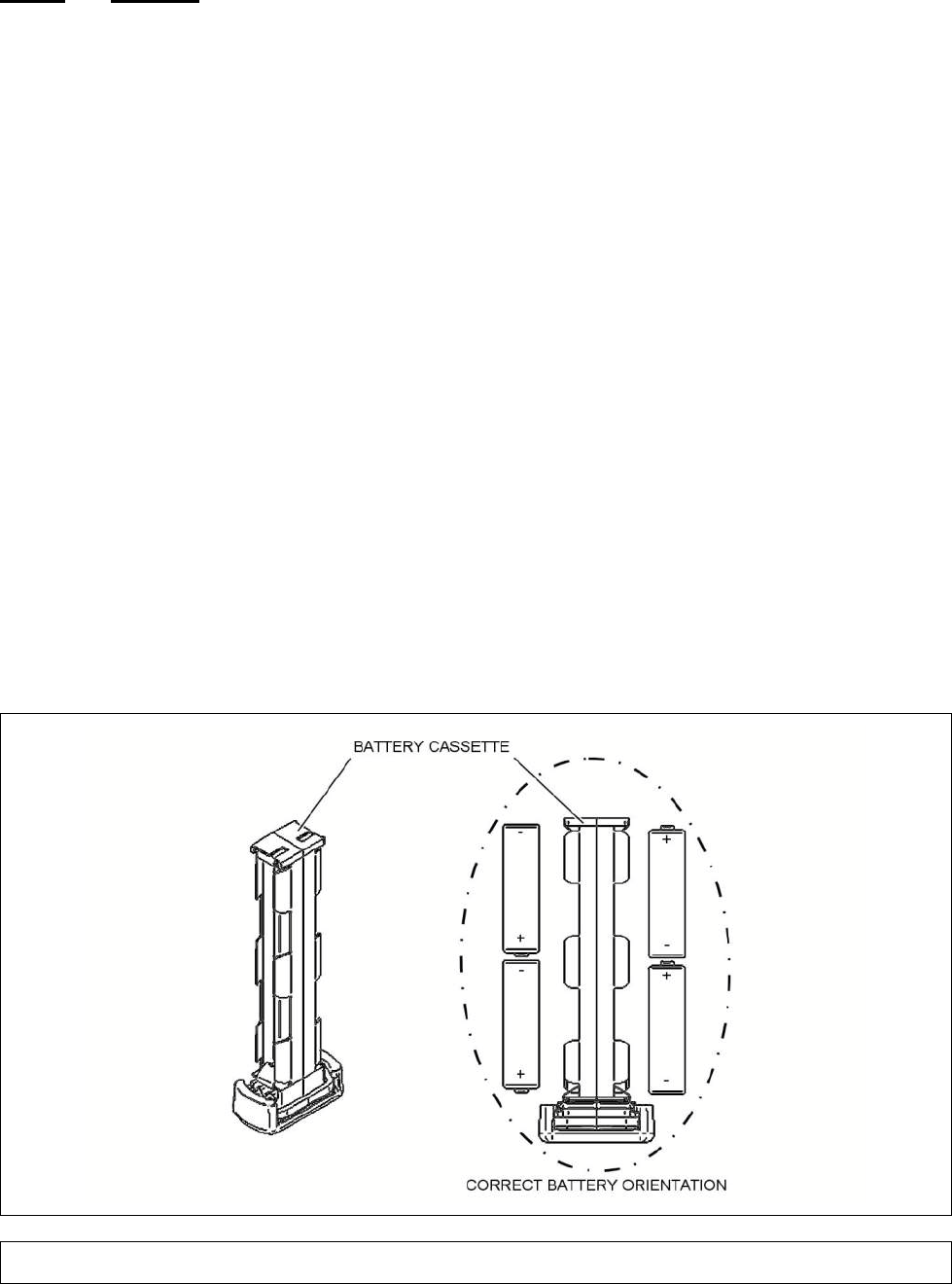
Chapter 5
Page 71
5.3.1.3 Pouches
1 Use a blotting cloth to remove any liquid contamination from the equipment.
2 Wash the pouch in hand-hot (100ºF (38ºC)) soapy water. Pouches can be fully submerged.
3 Rinse with clean water. Pouches can be fully submerged.
4 Apply a solution of sodium hypochlorite to a concentration of between 10% and 12% available
chlorine with a small, stiff bristled brush or similar as required and submerge and soak in the solution
for a minimum of 15 minutes and maximum of 30 minutes.
5 Rinse with clean water and dry using lint-free cloth.
6 Allow the pouch to dry for a further 40 minutes minimum in a well ventilated environment. Dry in
a fume hood or an appropriate open-air site.
7 Perform post decontamination checks. See paragraph 5.3.2.
5.3.2 Post Decontamination Checks
After the decontamination procedure has been completed, check the equipment using an
appropriate CWA Detector in survey role, e.g. CAM. If CWA vapor is detected, allow further time in a
ventilated environment, e.g. 24 hours. If contamination is persistent, put the equipment back through
the decontamination procedure.
If required record the performance of the decontamination exercise.
Re-assemble the equipment and carry out a Functional Test to confirm that the equipment is ready
for normal operation.
5.3.3 Replace Sensor Node Batteries or Battery Cassette
Figure 62 Sensor Node Batteries or Battery Cassette Replacement
1 If the Sensor Node is operating, shut down by pressing the button on the top of the Sensor
node. Wait for 3 seconds so that the Sensor Node can shut down correctly.
2 Open the Battery Cassette Locking Cover.
Chapter 5
Page 72
3 Fully withdraw the Battery Cassette from the Sensor Node.
WARNING –BATTERIES
THE SENSOR NODE CAN USE EITHER LITHIUM IRON DISULFIDE
AA NON
RECHARGEABLE BATTERIES OR ALKALINE MANGANESE DIOXIDE
AA NON
RECHARGEABLE BATTERIES. THESE BATTERIES
ARE A FLAMMABLE,
CORROSIVE AND VAPOUR HAZARD. THE LITHIUM IRON DISULFIDE BATTERIES
CONTAIN LITHIUM AND AN ELECTROLYTE. THE LITHIUM REACTS VIGOROUSLY
WHEN IMMERSED IN WATER. THE ELECTROLYTE IS FLAMMABLE AND HIGHLY
CORROSIVE:
DO NOT IMMERSE BATTERIES IN WATER, DECONTAMINANT SOLUTION OR
OTHER LIQUIDS.
DO NOT CRUSH OR BURN BATTERIES.
DO NOT ATTEMPT TO RECHARGE BATTERIES.
DO NOT STORE BATTERIES AT TEMPERATURES ABOVE 158°F (70°C).
IN THE EVENT THAT A BATTERY WITHIN THE RADIO MODEM IS SHORTED OR
STARTS TO HEAT UP, IT SHOULD BE REMOVED FROM THE UNIT AND TAKEN TO
THE OUTDOORS OR TO A WELL VENTILATED AREA TO COOL DOWN. ONCE THE
TEMPERATURE HAS DROPPED THE BATTERY CAN BE DISPOSED OF ACCORDING
TO LOCAL PROCEDURES FOR HAZARDOUS WASTE.
SUITABLE PROTECTIVE
CLOTHING SHOULD BE WORN WHEN HANDLING SUSPECT BATTERIES. IF THE
SKIN OR EYES COME INTO CONTACT WITH THE
ELECTROLYTE, WASH
THOROUGHLY WITH WATER AND SEEK MEDICAL ATTENTION.
WARNING – BATTERY DISPOSAL
BATTERIES CONTAIN HAZARDOUS SUBSTANCES.
ALWAYS DISPOSE OF
BATTERIES AS HAZARDOUS WASTE IN ACCORDAN
CE WITH THE LOCAL
RECOMMENDED PROCEDURES.
WARNING - BURNS
IF THE OUTER COVER OF A BATTERY INSTALLED IN THE BATTERY CAS
SETTE IS
DAMAGED, A SHORT CIRCUIT CAN OCCUR AND THE BATTERIES MAY OVERHEAT
.
ALWAYS CHECK THE OUTER COVER OF EACH BATTERY IS UNDAMAGED BE
FORE
INSTALLING IN THE BATTERY CASSETTE.
4 Remove the four batteries from the Battery Cassette and discard in accordance with local
regulations.
CAUTION – Mixing Battery Types.
Mixing lithium and alkaline battery types within the Battery Cassette may cause
damage to the sensor node. Do not mix lithium and alkaline battery types within the
Battery Cassette.
CAUTION – Equipment damage.
Batteries inserted into the Sensor Node in the incorrect orientation may cause
damage. Always make sure the batteries are inserted in the correct orientation.
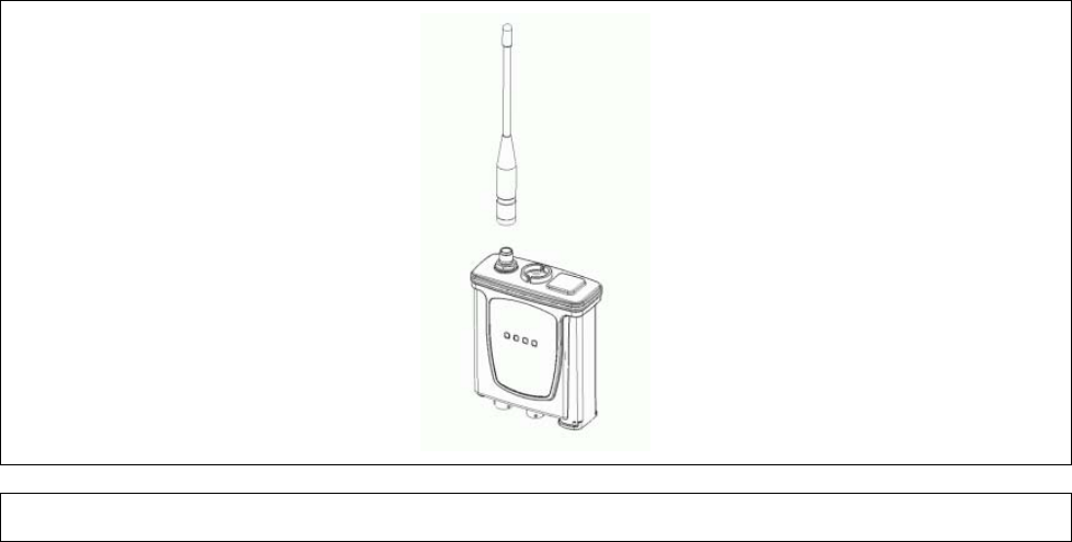
Chapter 5
Page 73
CAUTION – Mixing Batteries of different ages
Mixing exhausted and fresh within the Battery Ca
ssette may cause damage to the
Sensor Node. Do not mix batteries of different ages within the Battery Cassette.
CAUTION – Equipment Contamination
Contamination can enter the interior of the Sensor Node through the battery cassette
compartment. This may
cause the Sensor Node to malfunction or cease to operate
altogether. Make sure that the battery cassette is removed only when required.
5 Inspect the Battery Cassette for damage or degradation. If there is significant damage or
degradation discard the Battery Cassette and obtain a replacement.
6 Install four fresh batteries into the Battery Cassette in the correct orientation as marked on the
cassette.
7 Insert the loaded Battery Cassette fully into the battery compartment and close the Battery
Cassette Locking Cover.
5.3.4 Replace Sensor Node Antenna
Figure 63 Radio Modem Antenna Replacement
1 If the Sensor Node is operating shut down by pressing the on-off button.
2 Remove and discard the Antenna.
3 Install the replacement Antenna making sure that it is the correct one for the Sensor Node.
5.3.5 Replace Inoperative Sensa-LINX Equipment
In the event of any item of Sensa-LINX equipment malfunctions, or ceases to operate altogether,
obtain a replacement item. For information on spares see section 6.1. Dispose of equipment in
accordance with approved procedures. If equipment is contaminated with harmful substances make
sure that items are disposed of carefully and in accordance with approved procedures for disposal of
hazardous waste.

Chapter 5
Page 74
5.4 FAULT ANALYSIS
This section is divided into two parts – equipment faults not indicated by the system, and faults that
are indicated to the user, either by LED status at the Sensor Node or on the user interface at the
Controller.
5.4.1 Fault Diagnosis
This section covers equipment faults that do not produce any fault indications.
TABLE 36. BASE STATION AND SENSOR NODE RADIO MODEM FAULTS
Fault Cause/Effect Corrective Action
After button
press, power
LED is not
illuminated
Radio Modem is
inoperable. Check the other LEDs: If none are illuminated it is likely
that the batteries are fully discharged.
Re-press Radio Modem switch, change batteries and re-
try, or connect the Power Supply Unit and switch it on.
If there is still no power LED but there are other LEDs
illuminated, check Controller display: if the BSN or SN
icon is shown and there are no faults, the LED has failed.
To rectify, replace the Radio Modem and return for
repair.
GPS LED is not
illuminated
The Position
function of Radio
Modem is inoperable
Note: It can take up to 10 minutes for the GPS to achieve
a lock (particularly if the unit has been off for a long
period of time or has been moved a large distance since
it last achieved a GPS lock). Also note that a GPS lock
will not generally be achieved inside buildings or in
heavily built up areas.
Check the Radio Modem is switched on – look for green
Power LED or check the C2 display for the BSN or SN.
Move the Radio Modem clear of overhead obstructions to
get a better view of the sky.
Battery Low
LED does not
illuminate before
batteries fail.
The Battery Low
function has failed or
the LED has failed.
Check external power is not connected.
Replace the Radio Modem and return for repair.
Radio Modem is
working as
indicated by
Power, GPS
and/or Radio
Link LEDs but is
not recognized
by the sensor.
Data reporting is not
possible.
Check the sensor is set up to communicate with the
sensor node.
Check the connections. Replace cable.
Replace sensor and return for repair.

Chapter 5
Page 75
TABLE 36. BASE STATION AND SENSOR NODE RADIO MODEM FAULTS
Fault Cause/Effect Corrective Action
Radio Link LED
is not
illuminated.
A radio link has not
been achieved. Note: It can take up to 1 minute
to achieve a radio link.
Allow sufficient time for this to occur.
Check the Radio Modem is switched on by checking the
power LED on the modem or by checking the C2 display.
Check the antenna is installed correctly.
Make sure there is a line of sight to the receiving
modem(s) and the range is less than
values listed in
section 1.4.3 for the radio variant.
Verify Network ID is set the same on all Sensor Nodes.
Verify Channel/Pattern i
s set the same on all Sensor
Nodes.
Verify encryption enable/disable is set the same for all
Sensor Nodes. Note: Encryption keys must be the same
on all Sensor Nodes for communications to be
established when encryption is enabled.
If still no LED, replac
e Radio Modem and return for
repair.
TABLE 37. LAPTOP PC FAULTS
Fault Cause/Effect Corrective Action
BSN is not
recognized by
the Laptop PC.
Sensa-
LINX C2
communications are
inoperable.
Check BSN is switched on and working correctly. Check
cable connections.
Check Comms settings in the Sensa-LINX C2.
Close Node Configuration Tool application if open.
Replace BSN and re-
try. If communications are
achieved, return defective Radio Modem for repair.
If still no communication, replace Laptop PC and return
for repair.
SNs are not
recognized by
the Laptop PC
The BSN Modem is
inoperable. Check the BSN is switched on. Check cable connections.
Not all SNs are
recognized by
the Laptop PC
There are faults at
the SN – refer to SN
faults above.

Chapter 5
Page 76
TABLE 37. LAPTOP PC FAULTS
Fault Cause/Effect Corrective Action
Does not power
up when
switched on with
external power.
Does not power up
when switched on
with external power.
Replace Laptop PC and return for repair.
Does not power
up when
switched on with
battery power.
Does not power up
when switched on
with battery power.
Connect to e
xternal power. If still inoperable, replace
Laptop PC and return for repair.
If operable with external power the battery needs
charging. Run with external power until battery is
charged.
If battery charging has been attempted but still unable to
power up
from the battery, replace the battery and
dispose of the old one in accordance with local
regulations. Note: Lithium Ion.
Battery life is
very short Laptop PC
must be
run from external
power.
Connect to external power. Replace internal re-
chargeable battery pack and charge up.
TABLE 38. GENERAL FAULTS
Fault Cause/Effect Corrective Action
Equipment
Damage
Visible damage to
equipment Repair damaged items by replacement. See corrective
maintenance TABLE 35 for the list of replaceable items.
If damage is not repairable obtain replacement
equipment. Return faulty items for repair.
Map license
requires repair Map is not displayed The license for the Sensa-
LINX C2’s mapping
capabilities is automatically activated and deactivated
when the C2 is installed and uninstalled.
During the
activation process, your computer’s hardware profile is
used in order to bind the license to your machine. If,
after license activation, the hardware profile of your
machine changes significantl
y, it is possible that the
binding may break resulting in the mapping capabilities
of the C2 to stop working.
If this happens, simply
generate a new binding by running RepairASR.exe
located in the ‘ESRI License Activation’ directory under
the Sensa-LINX C2 installation directory. If this does not
resolve the issue, contact customer services listed in
Foreword section of this document.

Chapter 5
Page 77
5.4.2 Fault Messages
This section covers faults that produce indication, by LED status at the Sensor Node or on the user
interface at the Controller.
TABLE 39. BASE STATION FAULT MESSAGES
Message Cause/Effect Corrective Action
No GPS
Comms
The BSN cannot
communicate with the
internal GPS receiver.
Position cannot be
determined.
Cycle the BSN Power.
If unsuccessful, replace the BSN and return for repair.
No GPS
reception
The BSN cannot
determine position. Note: It can take up to 10 minutes for the GPS to achieve
a lock (particularly if the unit has been off for a long
period of time or has been moved a large distance since
it last achieved a GPS lock). Also note that a GPS lock
will not generally be achieved inside buildings or in
heavily built up areas.
Move the BSN clear of overhead obstructions to get a
better view of the sky.
If unsuccessful, replace the BSN and return for repair.
Battery Critical Battery life is very low. Replace the batteries in the BSN.
Duty Cycle
Alert
The 868 variant of
sensor node is
reaching its upper
duty cycle limit and
will soon cease
communicating.
Reduce the data rate of the network:
Set as many sen
sor nodes as possible to be
“Fixed” (see Section 3.4.6.1.6).
Reduce the number of sensor nodes on the
network.
Supply voltage
out of spec
The BSN cannot
operate from the
supply provided.
Correct the supply, whether external or due to incorrect
batteries fitted, or batteries fitted incorrectly.
BIT fail The BSN Built In Self
Test has failed and it
cannot detect faults.
Replace the BSN and return for repair.
Synth lock fail
The BSN transmitter
has failed. The unit
cannot communicate
with SNs.
Replace the BSN and return for repair.

Chapter 5
Page 78
TABLE 40. SENSOR NODE FAULT MESSAGES
Message Cause/Effect Corrective Action
No GPS Comms
The SN cannot
communicate with
internal GPS receiver.
Position cannot be
determined.
Cycle SN Power. If unsuccessful, replace Base
Station Radio Modem and return for repair.
No GPS
reception
The SN cannot
determine position.
Move the SN clear of overhead obstructions to get a
better view of the sky.
Battery Critical
Battery life is very low.
Replace the batteries in the SN.
Supply voltage
out of spec
The SN cannot
operate from the
supply provided.
Correct the supply, whether external or due to
incorrect batteries used, or batteries fitted incorrectly.
BIT fail
The SN Built In Self
Test has failed and it
cannot detect faults.
Replace the SN and return for repair.
Duty Cycle Alert
The 868 variant of
sensor node is
reaching its upper
duty cycle limit and
will soon cease
communicating.
Reduce the data rate from this sensor node by setting
it to be “Fixed” (see Section 3.4.6.1.6).
No Sensor
Comms
SN has lost
communication with
the associated
sensor.
Request that the sensor status and the SN
connections are checked, and relevant corrective
action is carried out.
Sensor protocol
mismatch
The Sensor Comms
protocol is set to GPS
not ADRS.
The SN cannot
communicate with the
sensor.
Request that the Detector Unit Comms is set to
ADRS. Refer to sensor Operators Manual for further
information on sensor set up and configuration.

Chapter 6
Page 79
*5 CHAPTER 6 SPARES INFORMATION
6.1 GENERAL
This section details the recommended spare parts, consumables and optional ancillaries for the
Sensa-LINX System.
TABLE 41. SPARE P ARTS
Item Part Number NATO Stock Number (NSN)
1 SYSTEM MANUAL 20270 7610-99-250-2360
2 AC ADAPTOR, PANASONIC CF31 3370-2530 6130-99-373-6412
3 LAPTOP, C2 20765 7010-99-815-0238
4 QUICK REFERENCE GUIDE 20449 7610-99-591-4923
5 LCD3.3 DOCK ASSY. 20420 5340-99-448-0573
6 SOFTWARE CD, SENSA-LINX 20451 7030-99-471-5953
7 SENSOR NODE ASSY, 2.4GHz INT,
GREEN 20399 6665-99-375-0324
8 SENSOR NODE ASSY, 2.4GHz STD,
GREEN 20399A 6665-99-601-9543
9 SENSOR NODE ASSY, 900MHz INT,
GREEN 20399B 6665-99-306-4353
10 SENSOR NODE ASSY, 900MHz STD,
GREEN 20399C 6665-99-814-5887
11 SENSOR NODE ASSY, 868MHz INT,
GREEN 20399D 6665-99-695-3724
12 SENSOR NODE ASSY, 868MHz STD,
GREEN 20399E 6665-99-355-4823
13 SENSOR NODE ASSY, 2.4GHz INT,
BLACK 20399F 6665-99-321-2716
14 SENSOR NODE ASSY, 2.4GHz STD,
BLACK 20399G 6665-99-169-4811
15 SENSOR NODE ASSY, 900MHz INT,
BLACK 20399H 6665-99-928-8068
16 SENSOR NODE ASSY, 900MHz STD,
BLACK 20399J 6665-99-979-2786
17 SENSOR NODE ASSY, 868MHz INT,
BLACK 20399K 6665-99-737-5529
18 SENSOR NODE ASSY, 868MHz STD,
BLACK 20399L 6665-99-297-8655
19 SENSOR NODE TRANSIT CASE 20403 8145-99-562-8505
20 BASE STATION TRANSIT CASE 20404 8145-99-915-8467

Chapter 6
Page 80
TABLE 41. SPARE P ARTS
Item Part Number NATO Stock Number (NSN)
21 ANTENNA, 868MHZ 20900 5985-99-254-7939
22 ANTENNA, 2.4GHZ STANDARD 20903 5985-99-690-7821
23 ANTENNA, 900MHZ 20901 5985-99-239-4949
24 ANTENNA, 2.4GHZ INTERNATIONAL 20902 5985-99-290-6918
25 SENSOR NODE POUCH, GREEN 20334 8465-99-726-6283
26 SENSOR NODE POUCH, BLACK 20334A 8465-99-494-2118
27 MOUNTING STRAP, GREEN 20735 5340-99-856-4468
28 MOUNTING STRAP, BLACK 20735A 5340-99-442-7408
29 BATTERY CASSETTE ASSEMBLY,
GREEN 20014 6160-99-993-1165
30 BATTERY CASSETTE ASSEMBLY,
BLACK 20014A 6160-99-877-4879
31 COMMS CABLE - SN TO NEXUS OR
PCA (3m) 20172 5995-99-880-0447
32 SCREW DRIVER 6.5mm X 30mm
PARALLEL 5749-0612 5120-99-587-3876
33 EUROPEAN MAP FILES DVD 20876 7030-99-925-1099
34 NORTH AMERICA MAP FILES DVD 20877 7030-99-407-2501
35 COMMS CABLE - SN TO LAPTOP (3m) 20173 5995-99-995-0754
36 COMMS CABLE - SN TO NEXUS OR
PCA (3m) 20172 5995-99-880-0447
37 DETECTOR POUCH, LCD3.3 (GREEN) 20335 8465-99-340-3087
38 DETECTOR POUCH, LCD3.3 (BLACK) 20335A 8465-99-173-1167
39 COMMS CABLE - SN to LCD3.3
(SHORT) 20175 5995-99-152-2369
40 COMMS CABLE - SN to LCD3.3
(SPIRAL) 20234 5995-99-152-2370
41 MAINS POWER ADAPTOR (GREEN) 20734 6130-99-464-9563
42 MAINS POWER ADAPTOR (BLACK) 20734A 6130-99-961-5920
43 POWER CABLE, UK 5356-5085 6150-99-213-7559
44 POWER CABLE, TRANSFORMER TO
SN / NEXUS (3m) 20174 6150-99-979-2782
45 POWER & COMMS CABLE, PCA & SN 20553 5995-99-958-6054

Chapter 6
Page 81
TABLE 41. SPARE P ARTS
Item Part Number NATO Stock Number (NSN)
46 PCA MOUNTING (GREEN) 20336 5340-99-248-5225
47 PCA MOUNTING (BLACK) 20336A 5340-99-853-3885
48 PCA (PIK) MOUNTING PLATE 20339 5340-99-856-4469
49 TRIPOD MOUNTING BRACKET 20330 5340-99-837-1194
50 TRIPOD 6881-0215
51 SENSOR NODE - NEXUS (PIK)
MOUNTING 20466 5340-99-814-5871
52 12-32VDC LAPTOP ADAPTOR 3330-5100 5895-01-577-7515
53 MAINS TRAVEL ADAPTOR 3370-2506 5935-99-155-5802
54 SHOULDER STRAP (GREEN) 5368-9020 8465-99-458-9745
55 SHOULDER STRAP (BLACK) 19268 8465-99-667-6259
56 USB CABLE ASSEMBLY 20966 5995-99-297-8667
Chapter 6
Page 82
This page is intentionally left blank
Appendix A
Page A-1
APPENDIX A
Node Configuration Tool User Instructions
Appendix A
Page A-2
This page is intentionally left blank
Appendix A
Page A-3
APPENDIX A - TABLE OF CONTENTS
1 Introduction .................................................................................................................. A-5
2 Application Overview ................................................................................................... A-5
3 Hardware Configuration ............................................................................................... A-5
4 Sensor Node Settings .................................................................................................. A-6
4.1 Displaying the Current Sensor Node Settings ................................................................. A-6
4.2 Change Sensor Node Settings Using the NCT ............................................................... A-7
4.3 Sensor Node Settings ..................................................................................................... A-8
4.3.1 Network Type ................................................................................................................. A-8
4.3.2 Network ID ...................................................................................................................... A-8
4.3.3 Network Channel Pattern ................................................................................................ A-9
4.3.4 Radio Power Level ......................................................................................................... A-9
4.3.5 Radio Encryption Enable ................................................................................................ A-9
4.3.6 Radio Encryption Key ..................................................................................................... A-9
4.3.7 Node Encryption Enable ............................................................................................... A-10
4.3.8 Node Encryption Key .................................................................................................... A-10
4.3.9 Hardware Version ......................................................................................................... A-10
4.3.10 Software Version .......................................................................................................... A-10
4.3.11 RADIO MAC ADDRESS ............................................................................................... A-10
4.3.12 OS VERSION & BUILD ................................................................................................ A-10
5 Updating Sensor Node Operating System ................................................................ A-11
5.1 Update Procedure ........................................................................................................ A-11
5.1.1 OS File Directory .......................................................................................................... A-11
5.1.2 Sensor Node OS Update Steps .................................................................................... A-11
6 Updating Sensor Node Application ........................................................................... A-14
6.1 Equipment Needed ....................................................................................................... A-14
6.2 Required Software Tools .............................................................................................. A-14
6.3 Update Procedure ........................................................................................................ A-14
6.3.1 Application File Directory .............................................................................................. A-14
6.3.2 Sensor Node Application Update Steps ........................................................................ A-14
7 Copy Sensor Node Log Files ..................................................................................... A-17
7.1 Required Software Tools .............................................................................................. A-17
7.2 Steps to Copy Log Files ................................................................................................ A-17
8 NCT Graphical User Interface .................................................................................... A-19
8.1 Main Screen ................................................................................................................. A-19
8.1.1 Title Bar ........................................................................................................................ A-19
8.1.2 Menu Bar ...................................................................................................................... A-19
8.1.3 Configuration Tool ........................................................................................................ A-21
8.1.4 Status Bar..................................................................................................................... A-22
9 Installation Of NCT ..................................................................................................... A-22
9.1 Setup of Active Sync on Windows XP ........................................................................... A-22
9.1.1 ActiveSync Installation For Windows XP ...................................................................... A-22
9.2 Setup of Mobile Media Center on Vista and W7 ........................................................... A-23
9.2.1 Windows Mobile Media Center Installation For Windows Vista and Windows 7 ........... A-23
9.3 NCT Software Installation ............................................................................................. A-23
9.4 Configuring the Manufacturing Tool .............................................................................. A-26
9.4.1 USB Ports Tab ............................................................................................................. A-27
Appendix A
Page A-4
This page is intentionally left blank

Appendix A
Page A-5
NETWORK CONFIGURATION TOOL (NCT)
USER INSTRUCTIONS
1 INTRODUCTION
The Node Configuration Tool (NCT) is a Windows Graphical User Interface (GUI) application that
allows an operator to view and configure various Sensor Node parameters and to update the Sensor
Node software. The NCT software runs on a Windows PC (XP, Vista, 7) and can communicate with
a sensor node using a RS-232 serial interface (or USB for software loading). Since the NCT uses a
single wired interface, it can only communicate with one sensor node at a time. On Laptop PCs
delivered as Sensa-LINX equipment the NCT Application is pre-installed. If there is a requirement to
re-install the application or to install the application onto another PC refer to section 9.
2 AP PLICATION OVERVIEW
The NCT supports the following capabilities:
• To display and change current sensor node settings. The sensor nodes come with a standard
configuration that allows the Sensor Nodes to operate in a normal manner. However some
settings can be changed to alter or improve performance in certain circumstances. See Section
4.1 for details on how to do this.
• To update the Sensor Node Operating System (OS). This will only be required if a system
software update has been received from Smiths Detection with a new version of the OS included
and should only be performed in these circumstances. See Section 4 for details on how to do
this.
• To update the Sensor Node Application. This will only be required if a system software update
has been received from Smiths Detection and should only be performed in these circumstances.
• To copy the Sensor Node log files to a local PC directory. This will only be required if Smiths
Detection request the log files for analysis and should only be performed in these circumstances.
See Section 7 for details on how to do this.
Section 8 provides a detailed reference to each of the NCT features.
Section 9 provides instructions on how to install the NCT on a new computer (note that the NCT is
pre-installed on any computer delivered as part of a Sensa-LINX system).
3 HARDWARE CONFIGURATION
Figure 1 shows the hardware setup used to configure a sensor node using the NCT. It consists of a
PC connected to a sensor node via a wired serial cable. The NCT does not support configuring
sensor nodes via a wireless interface.
Figure 1 Hardware Configuration
When using the NCT to read and write sensor node parameters (see Section 4) then the standard
RS232 cable can be used to connect the C2 laptop to the Sensor Node (in the same way as
normally connected when using the Sensor Node as a basestation).

Appendix A
Page A-6
However, if using the NCT to update the Sensor Node OS, application software or to read Sensor
Node log files, then both an RS232 and a USB port need to be connected to the Sensor Node. This
requires the special cable RS232/USB that is provided with a C2 computer.
4 SENSOR NODE SETTINGS
Caution: Sensor Node Settings.
Changing these settings on a Sensor Node can adversely affect its performance. Read this section
carefully before changing the settings and only make a change if you are confident that you
understand the implications. Refer to Smiths Detection for assistance if in doubt.
This section describes the steps required to change the configuration settings in the sensor node.
These steps assume that the NCT software is already installed on the computer.
Note:
When you are finished making any/all configuration changes to a sensor node, you MUST
cycle power on the sensor node before using it in a network configuration.
4.1
DISPLAYING THE CURRENT SENSOR NODE SETTINGS
To connect to a Sensor Node and show the current settings:
1 Attach the serial cable to the computer’s serial port (use the standard RS232 cable that is used
to connect a Sensor Node as a basestation).
2 Start the NCT application.
3 Click the ‘Connect’ button and select the desired COM port (the first time the NCT runs this will
default to COM1, it will only need to be changed if you are using a different port).
4 Attach the sensor node end of the serial cable to the sensor node.
5 Turn on the sensor node power.
6 Wait for the NCT to establish a link with the sensor node.
7 When a link is made the NCT will automatically get and display the sensor nodes current
settings. The Network Type of the attached sensor node will be automatically added to the new
settings column. See Figure 2.
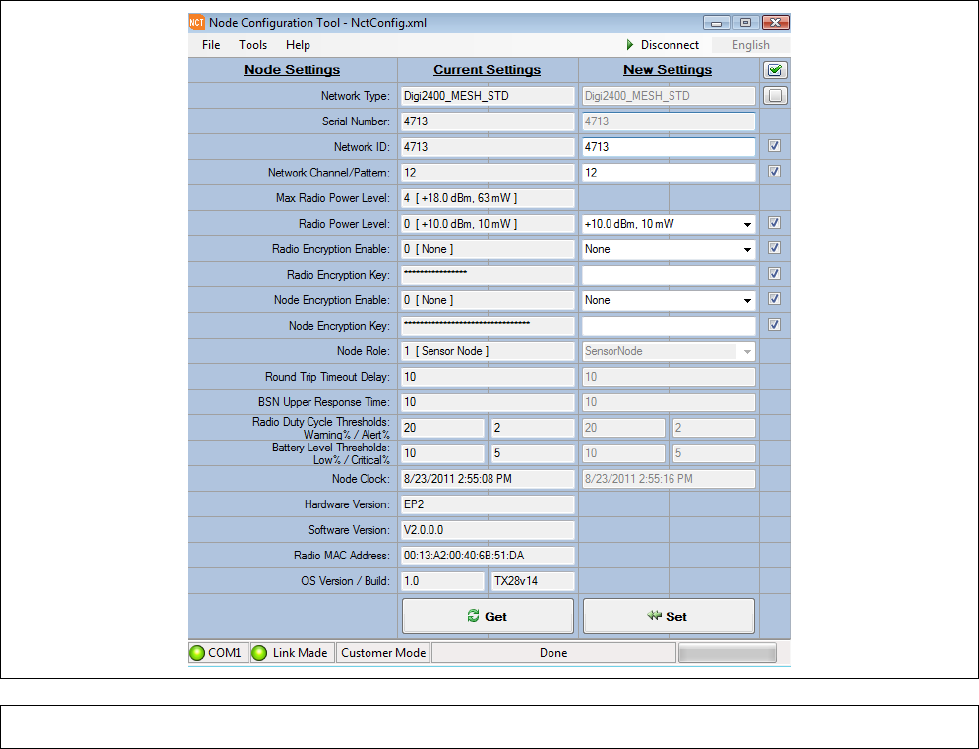
Appendix A
Page A-7
Figure 2 NCT Main Screen Showing the current Sensor Node settings
4.2
CHANGE SENSOR NODE SETTINGS USING THE NCT
To change the settings on a Sensor Node:
1 Change the values in the “New Settings” column that you wish to alter and tick the check box
next to each setting that you wish to change.
2 Verify that the new settings are set to the desired values and that the check box next to each
setting you want to change is checked.
3 Click the ‘Set’ button. When the set operation is complete, the NCT will automatically get and
display the sensor nodes current settings.
4 Verify that the desired changes now appear in the current settings column.
5 Power down the sensor node and remove it from the serial cable.
6 Steps 3–9 can be repeated with additional sensor nodes.

Appendix A
Page A-8
4.3
SENSOR NODE SETTINGS
This section describes the sensor node settings that can be read and (in some circumstances)
altered by the user.
The NCT provides the following capabilities to read or write sensor node settings:
Sensor Node Setting
Capability
Network Type
Read
Serial Number
Read
Network ID
Read/Write
Network Channel
Read/Write
Max Radio Power Level
Read
Radio Power Level
Read/Write
Radio Encryption Enable
Read/Write
Radio Encryption Key
Write
Node Encryption Enable
Read/Write
Node Encryption Key
Write
Node Role
Read
Round Trip Timeout Delay
Read
BSN-IN Upper Response Time
Read
Radio Duty Cycle Thresholds
Read
Battery Level Thresholds
Read
Sensor Node Clock
Read
Hardware Version
Read
Software Version
Read
Radio MAC Address
Read
OS Version & Build
Read
Update Sensor Node OS
Write
Update Sensor Node Application
Write
Copy Sensor Node Log Files
Read
The following sections provide information on the Sensor Node Settings in detail.
4.3.1 NETWORK TYPE
Used to determine the network type of the sensor node. This setting indicates the type of radio that
is installed in the sensor node. This value is determined by the type of radio that is installed in the
sensor node and can not be changed using factory, developer, or customer access mode.
Note: The network type is a read-only setting and can not be changed.
Value
Network Type
1
Digi 868MHz Point-To-Multipoint (PTMP)
2
Digi 900MHz Mesh Network
3
Digi 900MHz Mesh Network
4
Digi 2.4GHz Mesh Network
5 Digi 2.4GHz Mesh Network (reduced TX power
option)
4.3.2 NETWORK ID
Used to configure the sensor node to a specific network ID. All sensor nodes that are required to
communicate on a network MUST have the same Network ID. The network ID allows 1 or more co-
located networks to operate without being logically joined (i.e. a broadcast on one will not propagate
to the other, and in a meshing environment the networks with different network ID will not mesh
together.
Note: The network ID is a read-write setting.

Appendix A
Page A-9
Type of Network
Min Value
Max
Value
Digi 868MHz PTMP Network
0
32767
Digi 900MHz Mesh Network (All
variants)
0
32767
Digi 2.4GHz Mesh Network (All
variants)
0
65535
4.3.3 NETWORK CHANNEL PATTERN
Used to configure the sensor node to a specific RF Channel. All sensor nodes that are required to
communicate on a network must have the same network channel/pattern.
Note: The network channel/pattern is a read-write setting.
Type of Network
Min Value
Max
Value
Digi 868MHz PTMP Network
Not Supported
Digi 900MHz Mesh Network (standard variant)
0
7
Digi 900MHz Mesh Network (international
variant)
0
3
Digi 2.4GHz Mesh Network (All variants)
12
23
4.3.4 RADIO POWER LEVEL
Used to get/set the transmit power level that the radio module is set to. The values displayed in the
Radio Power Level drop-down control are determined by the selected setting in the Max Radio
Power Level drop-down control.
Note: The radio power level is a read-write setting.
Network Type
Value
Allowed Power Settings
Digi868_PTMP
0
1
2
3
4
0.0 dBm, 1 mW
+13.7 dBm, 23 mW
+20.0 dBm, 100 mW
+22.0 dBm, 158 mW
+25.0 dBm, 316 mW
Digi900_MESH
0
+17.0 dBm, 50 mW
Digi900_MESH_RCO
0
+17.0 dBm, 50 mW
Digi2400_MESH
0
1
2
3
4
+10.0 dBm, 10 mw
+12.0 dBm, 16 mW
+14.0 dBm, 25 mW
+16.0 dBm, 40 mW
+18.0 dBm, 63 mW
Digi2400_MESH_RTO
4
+10.0 dBm, 10 mW
Caution: When adjusting the Radio Power Level, care must be taken to not set a level that
would breach the local licensing rules for the geographical area where the node will be used.
4.3.5 RADIO ENCRYPTION ENABLE
Used to enable or disable radio encryption in the sensor node.
Note: The radio encryption enable is a read-write setting.
4.3.6 RADIO ENCRYPTION KEY
Used to set the radio encryption key of the sensor node. The user can either enter a Hex encryption
key or generate one automatically using the ToolsGenerate Radio Key menu item. When this
Appendix A
Page A-10
menu item is selected, an AES-128 key is automatically pasted into the Radio Encryption Key
control in the New Settings column.
The radio encryption key is a write-only settings; therefore, ‘********’ is displayed in the current
settings column.
Caution: The radio encryption key is a write-only setting. Each sensor node in a network
must have the same encryption key to be able to communicate with each other. Since the
encryption key can not be read back, it is highly recommended that the key be recorded. The
key could be saved in a configuration file so that it can be used to configure other sensor
nodes that are added to the same network at a later time. Refer to 8.1.2.1 for information on
opening and saving configuration files.
4.3.7 NODE ENCRYPTION ENABLE
Used to enable or disable the node encryption in the sensor node.
Note: The node encryption enable is a read-write setting.
4.3.8 NODE ENCRYPTION KEY
Used to set the node encryption key of the sensor node. The user can either enter a Hex encryption
key or generate one automatically using the ToolsGenerate Node Key menu item. When this
menu item is selected, the 16-byte FIPS key is automatically pasted into the Node Encryption Key
control in the New Settings column.
The node encryption key is a write-only settings; therefore, ‘****************’ is displayed in the current
settings column.
Caution: The node encryption key is a write-only setting. Each sensor node in a network
must have the same encryption key to be able to communicate with each other. Since the
encryption key can not be read back, it is highly recommended that the key be recorded. The
key could be saved in a configuration file so that it can be used to configure other sensor
nodes that are added to the same network at a later time. Refer to 8.1.2.1 for information on
opening and saving configuration files.
4.3.9 HARDWARE VERSION
Used to get the hardware version of the sensor node.
Note: The software version is a read-only setting and can not be changed.
4.3.10 SOFTWARE VERSION
Used to get the software version of the sensor node.
Note: The software version is a read-only setting and can not be changed.
4.3.11 RADIO MAC ADDRESS
Used to get the MAC address of the sensor node radio.
Note: The Radio MAC Address is a read-only setting and can not be changed.
4.3.12 OS VERSION & BUILD
Used to get the OS version & build information of the sensor node.
Note: The OS version & build is a read-only setting and can not be changed.
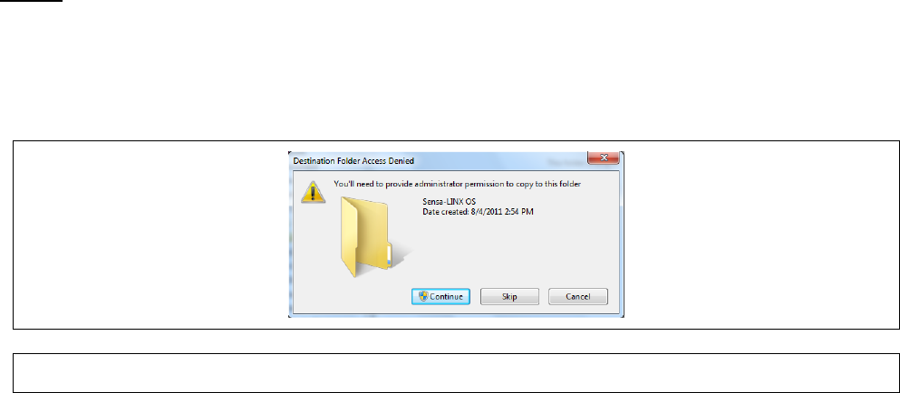
Appendix A
Page A-11
5 UPDATING SENSOR NODE OPERATING SYSTEM
Caution: Sensor Node Operating System Settings.
Changing the Operating System or Software on a Sensor Node can adversely affect its performance
and may render it inoperable if not performed correctly. Only update the Sensor Node with software
provided by Smiths Detection. Only update those Sensor Nodes for which the software is intended.
Read this section carefully before changing the software and only make a change if you are
confident that you understand the procedure. Refer to Smiths Detection for assistance if in doubt.
This section describes the steps required to update the Windows CE Operating System on the
sensor node.
5.1
UPDATE PROCEDURE
This section describes the steps required to update the Windows CE operating system in the sensor
node.
5.1.1 OS FILE DIRECTORY
The updated OS file will be delivered on computer media and will have a name that indicates the
current version number similar to NK_SN_EP2_V1.20_Tx28.nb0. This file must be copied from the
computer media into the directory shown below and renamed to NK.nb0.
“C:\Program Files\Smiths Detection\Sensa-LINX\Sensa-LINX NCT\mfgtools\Profiles\TX28 WinCE
Update\OS Firmware\files\”
Notes:
1. The above folder name assumes that the NCT was installed in the default location of
C:\Program Files\Smiths Detection\Sensa-LINX\Sensa-LINX NCT\
2. Administrator privileges are required to copy a file into the folder. If you are logged in as
a user, you will see the dialog shown in Figure 3 and will be required to enter in the
Administrator password to copy the file into this directory.
Figure 3 Destination Folder Access Denied Dialog
5.1.2 SENSOR NODE OS UPDATE STEPS
1 Attach the Comms cable to the PC serial port and to the sensor node.
2 Start the NCT application, click the ‘Connect’ button, and select the COM1 port.
3 Turn ‘ON’ the sensor node power.
4 Wait for the NCT to establish a link with the sensor node. When a link is made the NCT will
automatically get and display the sensor nodes current settings. The sensor node Network
Type will be added to the new settings column.
5 Make note of the OS version and build numbers that are displayed in the current settings
column.
6 In the Tools menu, select the “Update Sensor Node Operating System…” menu item. When
the Reprogram Warning seen in Figure 4 appears, select ‘Yes’ to continue or ‘No’ to quit.
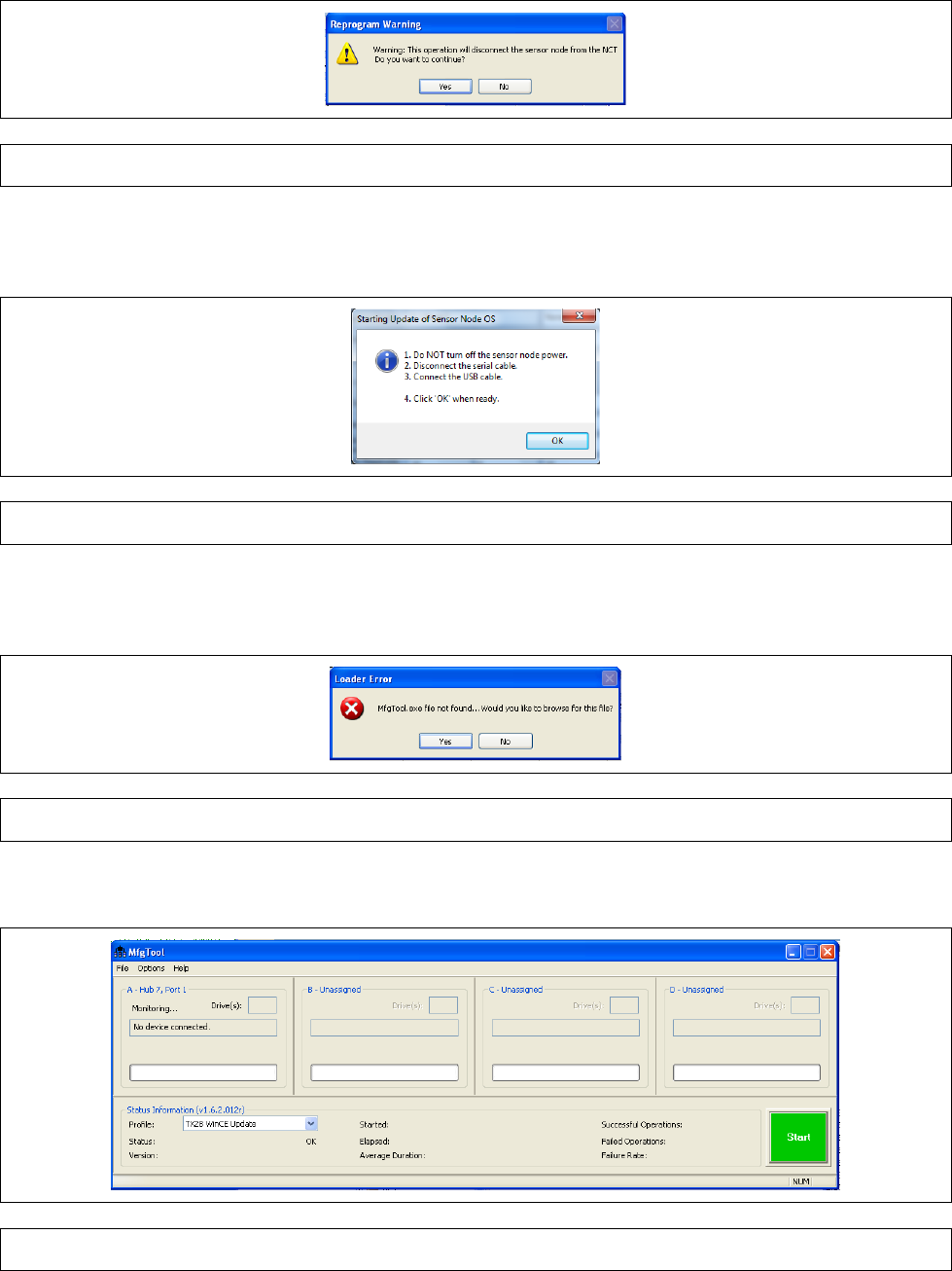
Appendix A
Page A-12
Figure 4 Reprogram Warning Dialog
7 When the Starting Update of Sensor Node OS dialog shown in Figure 5 appears, follow the
steps outlined in the dialog.
Figure 5 Starting OS Update Dialog
8 If the reprogramming software is not found then the dialog shown in Figure 6 will allow you to
browse to the MfgTool.exe file.
Figure 6 Loader Error Dialog
9 If the loading of the Manufacturing Tool is successful, the dialog shown in Figure 7 is displayed.
Figure 7 MfgTool Main Screen
10 If the MfgTool has not been previously configured then execute the steps listed in paragraph
9.4 “Configuring the Manufacturing Tool” before continuing to the next step.
11 In the left hand pane A, verify that the Monitoring… text control displays “No device connected”
and the Profile drop-down list control is set to “TX28 WinCE Update”.
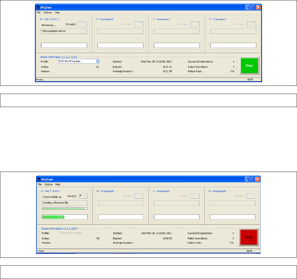
Appendix A
Page A-13
12 Plug the sensor node USB connector into the PC.
13 If the sensor node is detected the Monitoring… text control should display “HID-compliant
device” as shown in Figure 8.
Figure 8 MfgTool Connected
14 Click on the green Start button. The sensor node software should start loading as seen by the
progress bars in Figure 9.
Caution:
Turning OFF the sensor node power during this operation could result in a corrupted OS and
the sensor node will have to be returned to the factory for repair.
Figure 9 MfgTool Busy
15 When the software update is complete the MfgTool Monitoring… text control should display
“FSL UUC USB Device” and the Successful Operations counter should have incremented.
16 Click the Stop button to halt ‘MfgTool’.
17 Disconnect the USB connector from the PC.
18 Turn ‘OFF’ the sensor node power.
19 Wait a few seconds and turn ‘ON’ the sensor node power.
20 When the NCT links with the sensor node and loads the current settings, verify that the
Software Version has changed from what was noted in step 6.
21 Turn ‘OFF’ the sensor node power and disconnect it from the serial cable.
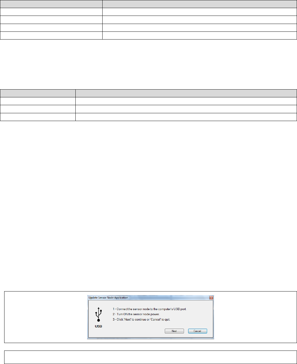
Appendix A
Page A-14
6 UPDATING SENSOR NODE AP P LICATION
This section describes the steps required to update the sensor node Application file.
6.1
EQUIPMENT NEEDED
This section identifies the equipment needed to update the sensor node application file using the
NCT.
Part No.
Description
Toughbook laptop CF-31
20172
USB cable: Sensor Node to C2 laptop
2456502
Node configuration Tool Software
Sensor Node Application File
6.2
REQUIRED SOFTWARE TOOLS
To run the “Update Sensor Node Application” tool, certain tools must be installed prior to running the
NCT. The following table lists the required tool for each Windows operating system.
Operating System
Tool
Windows XP
ActiveSync
Windows Vista
Windows Mobile Media Center
Windows 7
Windows Mobile Media Center
Note: Installation instructions can be found for the above tools in Section 9.1 and Section 9.2.
6.3
UPDATE PROCEDURE
This section describes the steps required to update the sensor node application file.
6.3.1 APPLICATION FILE DIRECTORY
The updated sensor node application file will be delivered on computer media and will have a name
that indicates the current version number similar to SN_BSN_EP2_v1.37_Tx28.exe. This file should
be copied from the computer media into a folder on the C:\ drive where it can be accessed by all
users having either Administrator or User accounts.
Example Folder: “C:\Sensor Node Applications\”
6.3.2 SENSOR NODE APPLICATION UPDATE STEPS
1 Start the NCT application and select the COM1 port. Note that a COM port connection is not
really required to update the sensor node application.
2 In the Tools menu, select the “Update Sensor Node Application…” menu item. The Update
Sensor Node Application dialog should appear as seen in Figure 10.
Figure 10 Update Sensor Node Application Dialog
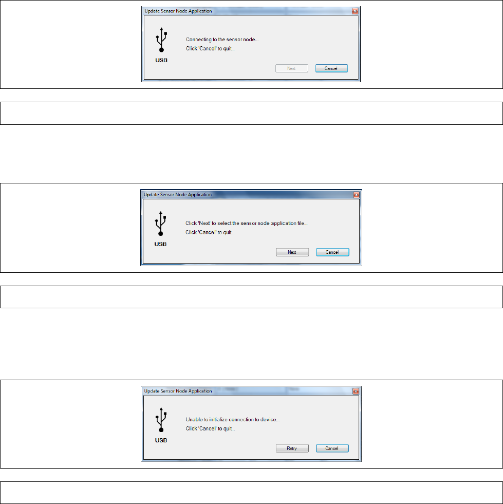
Appendix A
Page A-15
3 Connect the sensor node USB cable to the PC USB port and to the sensor node.
4 Turn ON the sensor node power.
5 Click the ‘Next’ button to continue. Note that the user can click the ‘Cancel’ button at any time
quit the update of the sensor node application.
6 If a Windows Mobile screen appears, select the “Connect without setting up the device” option
and then minimize the window.
7 Follow the instructions on the dialog and click the next button to continue
8 The dialog seen in Figure 11will be displayed while the NCT is attempting to connect to the
sensor node via the USB port.
Figure 11 Connecting to the sensor node dialog
9 When the NCT has connected to the sensor node, the dialog seen in Figure 12 will be
displayed. Click the Next button to select the sensor node application file to load.
Figure 12 Select sensor node application file dialog
10 If the NCT is unable to connect to the sensor node for any reason, the dialog seen in Figure
13will be seen. At this point you can click the Retry button to try again waiting at least 15
seconds between each retry.
Figure 13 Unable To Initialize Connection Dialog
11 The Select Sensor Node Application File dialog is displayed as seen in Figure 14. If the folder
containing the Sensor Node Application file is not shown in the dialog then select the folder
where the file was copied as described in paragraph 6.3.1.
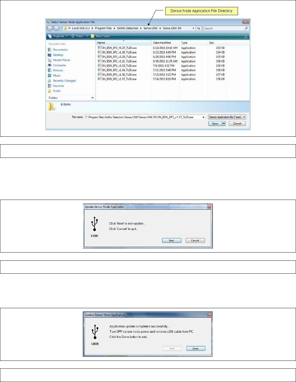
Appendix A
Page A-16
Figure 14 Select Sensor Node Application File Dialog
12 In the dialog shown in Figure 14, select the sensor node application file that was copied from
the CD in paragraph 6.3.1 and click the Open button. The Start Update dialog seen in Figure
15 will appear. Click the Next button to start the update.
Figure 15 Start Update Dialog
13 If the update completed successfully the dialog seen in Figure 16 will be shown. If the update
failed then the dialog seen in Figure 17 will appear indicating that the update failed.
Figure 16 Application Completed Successfully Dialog
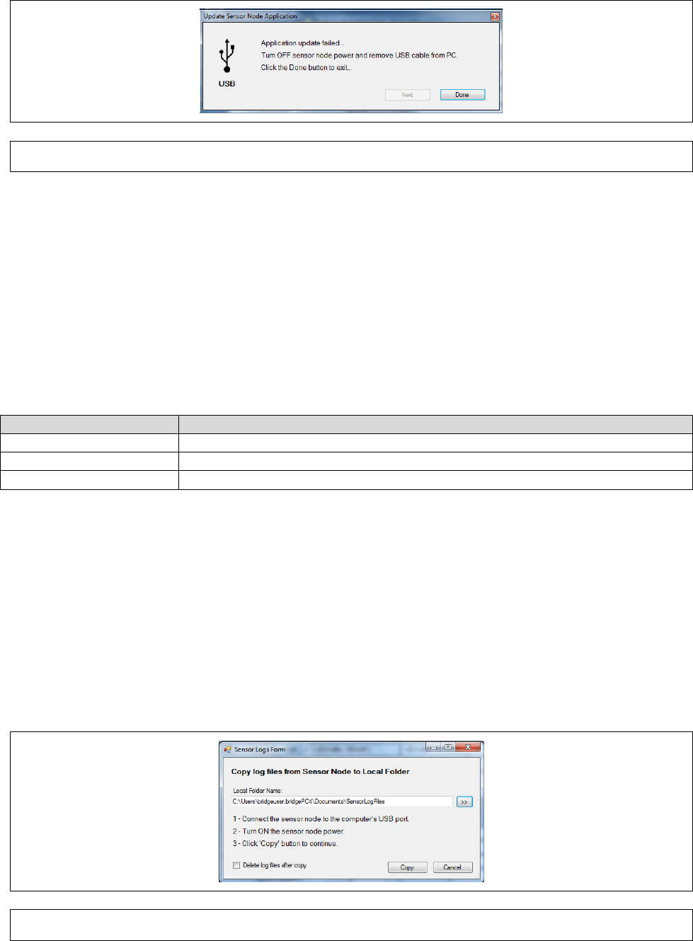
Appendix A
Page A-17
Figure 17 Application Update Failed Dialog
14 Click the Done button to exit the update mode.
15 Turn OFF the sensor node power and remove the USB cable from the PC.
16 Close the NCT application.
7 COPY SENSOR NODE LOG FILES
7.1
REQUIRED SOFTWARE TOOLS
To run the “Update Sensor Node Application” tool, certain tools must be installed prior to running the
NCT. The following table lists the required tool for each Windows operating system.
Operating System
Tool
Windows XP
ActiveSync
Windows Vista
Windows Mobile Media Center
Windows 7
Windows Mobile Media Center
Note: Installation instructions can be found for the above tools in Section 9.1 and Section 9.2.
7.2
STEPS TO COPY LOG FILES
The NCT provides a tool to allow the user to copy the log & xml files from the sensor node to a local
PC directory.
1 If the NCT application is not running then start it up and select the COM1 port. Note that a
COM port connection is not required to copy the sensor node log files.
2 Select the Tools->Copy Sensor Node Log Files… menu item which should display the Sensor
Logs Form shown in Figure 18.
Figure 18 Copy Sensor Logs Dialog
3 Connect the sensor node to the PC USB port and turn ON the sensor node power.
4 If the Local Folder Name text box does not contain a folder name you can either type one in or
use the Browse button to create a new folder or select an existing folder.
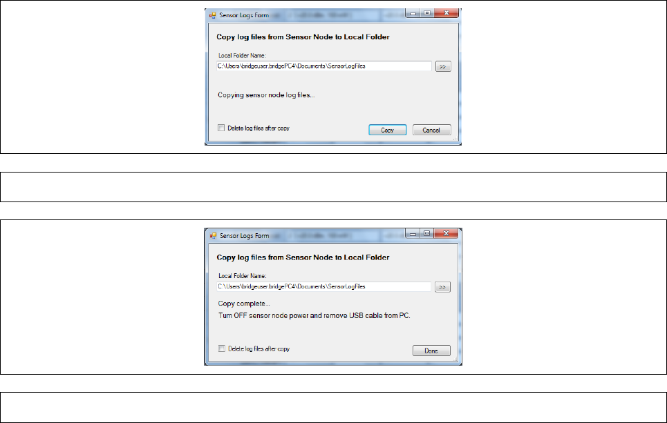
Appendix A
Page A-18
5 Check the ‘Delete log files after copy’ if you want to delete the log files on the sensor node after
they are copied.
6 Click the ‘Copy’ button to continue.
7 If a connection is made to the sensor node USB port, the dialog seen in Figure 19 is shown.
8 When the copy is complete the dialog seen in Figure 20 is shown.
9 Turn OFF the sensor node power, remove the USB cable from the PC, and click on the ‘Done’
button to exit.
Figure 19 Copying Sensor Node Log Files Dialog
Figure 20 Copy Complete dialog
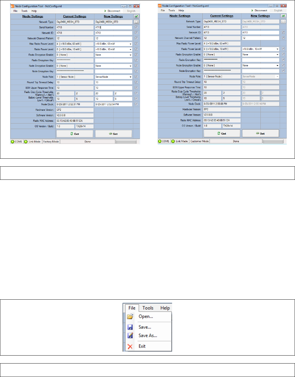
Appendix A
Page A-19
8 NCT GRAPHICAL USER INTERFACE
This section describes the features of the NCT in detail.
8.1
MAIN SCREEN
The Main Screen of the Node Configuration Tool (NCT) is shown in Factory Mode and in Customer
Mode in Figure 21. The Main Screen consists of a Title Bar, Menu Bar, Configuration Tool, and a
Status Bar.
Factory Mode Customer Mode
Figure 21 NCT Main Screen
8.1.1 TITLE BAR
The Title Bar is located at the top of the Main Screen and contains the application name (Node
Configuration Tool) and the name of the configuration file that is currently loaded (NctConfig.xml in
the sample screen shot).
8.1.2 MENU BAR
The Menu Bar is located directly beneath the Title Bar and give access to the File, Tools, and Help
menus.
8.1.2.1
FILE MENU
The File Menu shown in Figure 22, provides a menu to open and save NCT configuration files. The
various items shown in the File menu are given in TABLE 1 below.
Figure 22 File Menu
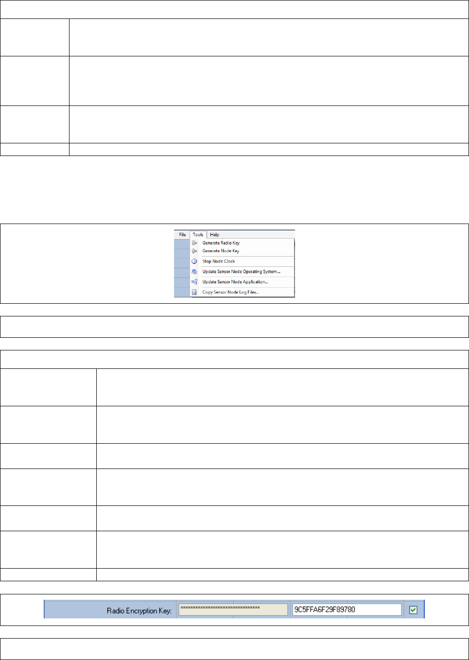
Appendix A
Page A-20
TABLE 1. FILE MENU ITEMS
Open
The ‘Open’ menu item is used to load a previously saved NCT configuration file.
The settings information contained in the configuration file are loaded into New
Settings column.
Save
The ‘Save’ menu item is used to save a NCT configuration file. A configuration file
can be used to save information that may be written to several sensor nodes that
will be part of a network. The data contained in the New Settings column is written
to the filename selected by the user.
Save As
The ‘Save As’ menu item is used to save NCT configuration settings to a different
file name. The file name of the saved configuration file is then displayed in the
main form title bar.
Exit
The ‘Exit’ menu item is used to close the NCT application.
8.1.2.2
TOOLS MENU
The ‘Tools’ menu, shown in Figure 23, provides a menu of various tools that are provided by the
application. The various items shown in the Tools menu are given in TABLE 2 below.
Figure 23 Tools Menu
TABLE 2. TOOLS MENU ITEMS
Generate Radio
Key This menu item is used to automatically generate an AES-128 encryption
key and insert the value into the Radio Encryption Key field in the New
Settings column as seen in Figure 24.
Generate Node
Key
This menu item is used to automatically generate a FIPS encryption key and
insert the value into the Node Encryption Key field in the New Settings
column.
Stop Node Clock
This menu item is used to start/stop the date-time updates in the Node
Clock field in the New Settings column.
Update Sensor
Node Operating
System
This menu item is used to launch a manufacturing tool that allows you to
update the sensor node Windows CE Operating System software. Refer to
section 5 for details on how to update the sensor node operating system.
Update Sensor
Node Application
This menu item is used to launch a GUI tool that allows you to update the
sensor node application software.
Copy Sensor
Node Log Files
This menu item is used to launch a GUI tool that allows you to copy the
sensor node log files to a local directory on the PC. Refer to section 7 for
details on how to copy the sensor node log files.
Figure 24 Radio Key
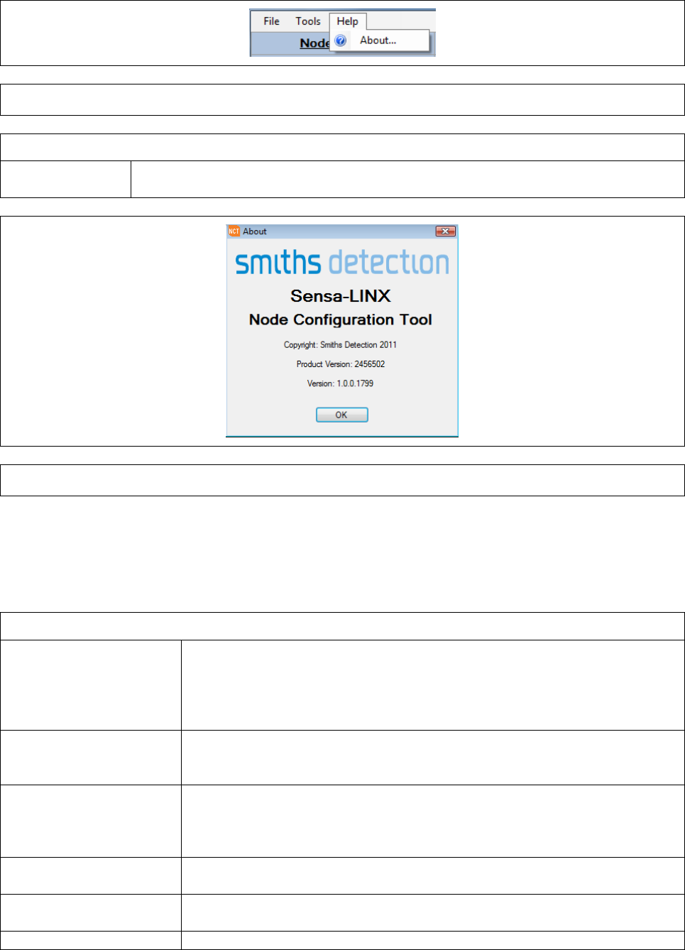
Appendix A
Page A-21
8.1.2.3
HELP MENU
The ‘Help’ menu shown in Figure 25provides an About menu item to view information about the NCT
application. See TABLE 3 below.
Figure 25 Help Menu
TABLE 3. TOOLS MENU ITEMS
About
The ‘About’ menu item is used to display information about the NCT
application. The About dialog is shown in Figure 26.
Figure 26 About Dialog
8.1.3 CONFIGURATION TOOL
The Configuration Tool area is below the menu bar and is used to get the current settings from the
sensor node and set new settings into the sensor node. The main components of the tool are
explained in TABLE 4 below.
TABLE 4. CONFIGURATION TOOL COMPONENTS
Current Settings
Column
The “Current Settings” column lists the decimal and string values of
the settings that are currently set in the connected sensor node.
These settings are automatically updated when a link is made to a
sensor node. These settings can be refreshed by clicking on the ‘Get’
button.
New Settings Column The “New Settings” column allows the user to enter the new settings
data that will be sent to the attached sensor node. These settings are
sent to the sensor node using the ‘Set’ button.
New Settings Check
Boxes
The “New Settings Check Boxes” are to the right of the new settings
column. These check boxes allow the user to select which settings to
update. The state of the check boxes is saved to the configuration file
so that they will be restored when the configuration opened.
Check All Button
This button has a checked check box icon and is used to check all of
the New Settings Check Boxes.
Uncheck All Button
This button has an unchecked check box icon and is used to uncheck
all of the New Settings Check Boxes.
Get Button
This button is used to refresh the current settings from the connected
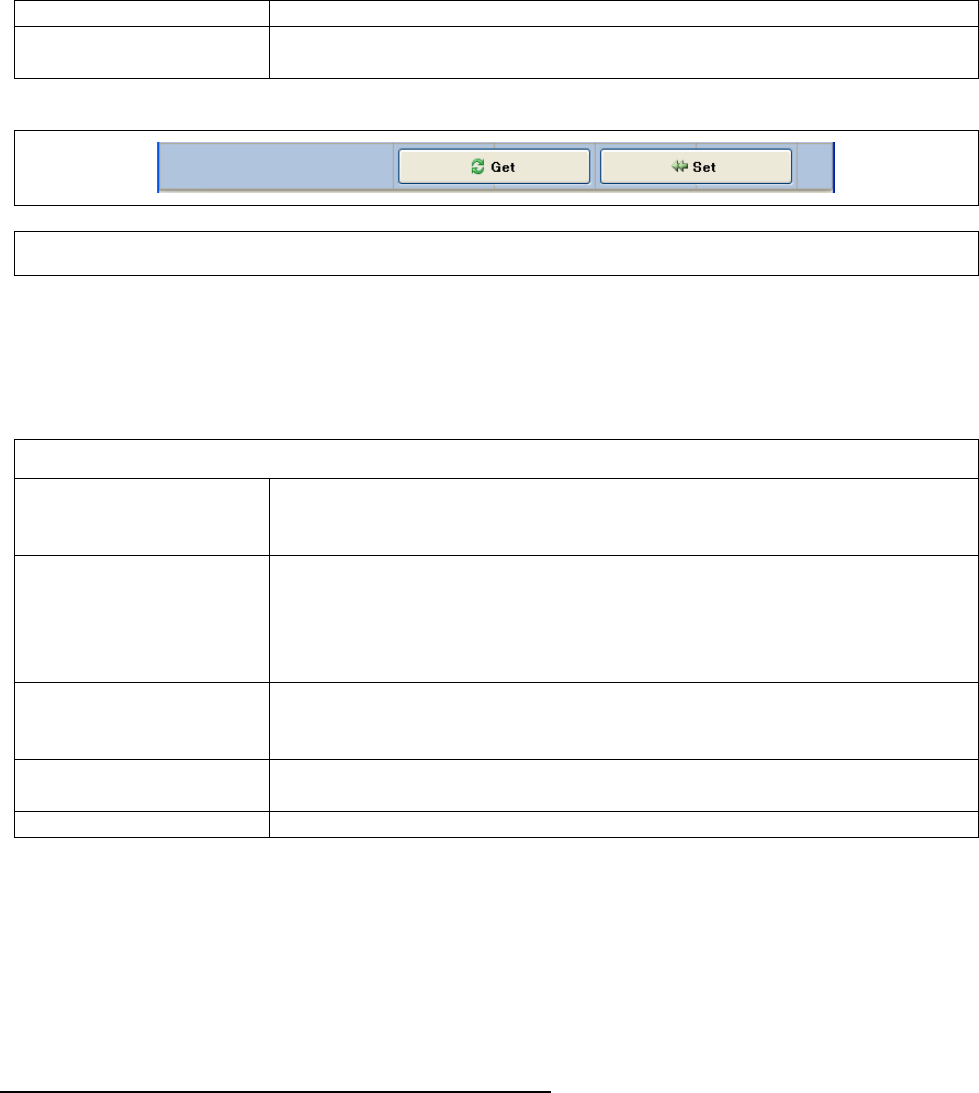
Appendix A
Page A-22
sensor node. See Figure 27.
Set Button
This button is used to send the new settings to the connected sensor
node. See Figure 27.
Figure 27 Get and Set Buttons
8.1.4 STATUS BAR
The Status Bar is located at the bottom of the main screen and contains a number of indicators to
display the status of various parts of the Sensa-LINX System. The displays and indications are
explained in TABLE 5 below.
TABLE 5. STATUS BAR DISPLAYS AND INDICATIONS
COM Port Status
Indicator
This status area displays a green LED image plus the name of the
COM port that is currently open. The LED is OFF when there is no
COM port connection and ON when a connection is made.
Link Status Indicator
This indicator displays a green LED image plus text that indicates the
current link status between the NCT and the Sensor Node. If a link
has not been established, the LED will be in the OFF and the text
displayed is “Link Down”. If a link has been established the LED will
be ON and the text displayed is “Link Made”.
Access Mode Indicator
This indicator displays text that indicates the access mode that the
application was installed with. There are three possible access
modes: Factory, Developer, and Customer.
Program Status
Indicator
This indicator displays the current NCT program status.
Get/Set Progress Bar
This indicator displays the progress of the Get and Set operations.
9 INS TALLATION OF NCT
The NCT is pre-installed on any Command and Control (C2) computer delivered as part of a Sensa-
Linx system. If it is required to install the NCT on any other computer, follow the procedure
described below.
9.1
SETUP OF ACTIVE SYNC ON WINDOWS XP
To run the “Update Sensor Node Application” and “Copy Sensor Node Log Files” tools on the NCT,
ActiveSync must be installed on Windows XP computers.
9.1.1 ACTIVESYNC INSTALLATION FOR WINDOWS XP
The following instructions are for the installation and setup of ActiveSync on a Windows XP
computer.
1 Connect the XP computer to the Internet and download ActiveSync 4.5 or greater from a
Microsoft web page.
2 Run the setup program and accept the default settings.
3 If the setup is successful, connect a sensor node to the computers USB port and turn on the
sensor node power.
4 Open up the “MyComputer” windows application. A Mobile Device icon should appear after
about 30 seconds under the Other label.
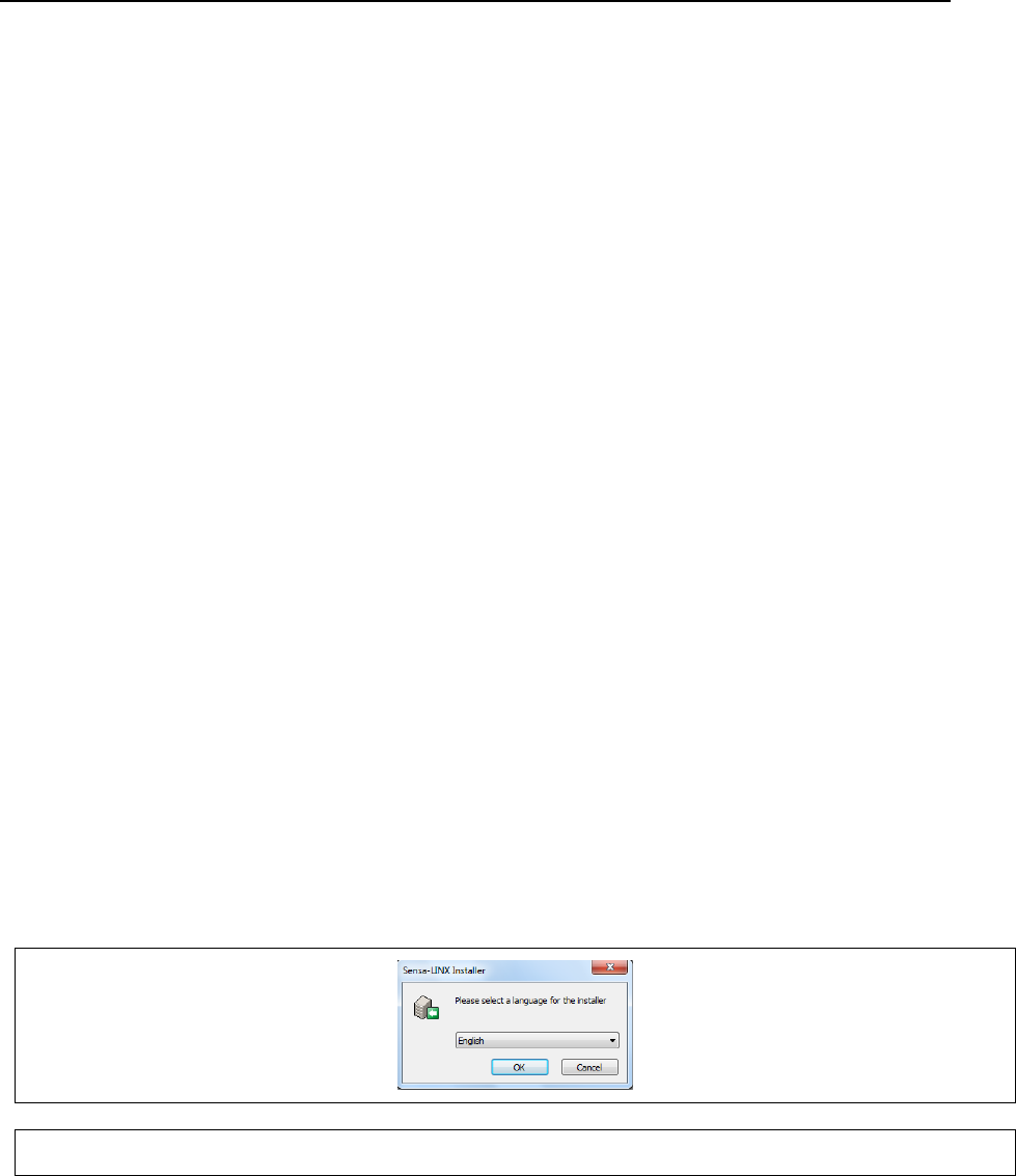
Appendix A
Page A-23
5 If the icon appears, the installation is complete and the NCT is ready to use. See section 9.3
for instructions on installing the NCT software.
9.2
SETUP OF MOBILE MEDIA CENTER ON VISTA AND W7
To run the “Update Sensor Node Application” and “Copy Sensor Node Log Files” tools on the NCT,
Windows Mobile Media Center must be installed on Windows Vista and Windows 7 computers.
9.2.1 WINDOWS MOBILE MEDIA CENTER INSTALLATION FOR WINDOWS VISTA AND
WINDOWS 7
The following are the installation and setup instructions of Windows Mobile Media Center (WMMC)
on a Windows Vista or Windows 7 computer.
1 Connect the computer to the Internet.
2 Connect a sensor node to the computers USB port and turn on the sensor node power.
3 If WMMC is not installed, Windows will automatically install it for you via the Internet
connection.
4 If the installation completes successfully, open up the “Computer” windows application. A
Windows CE icon should appear after about 30 seconds under the Portable Devices label.
5 If the Windows CE icon appears, the installation is complete and the NCT is ready to use. See
section 9.3 for instructions on installing the NCT software.
9.3
NCT SOFTWARE INSTALLATION
The NCT software and the Manufacturing tools required to update the sensor node OS are installed
as part of the Sensa-LINX Installer. Refer to “Uninstalling Sensa-LINX C2 and NCT” section in the
main document for uninstalling NCT software.
Notes:
• Before installing the NCT software, make sure that that you have performed the steps in
sections 9.1 or 9.2 for the operating system on the computer where NCT will be installed.
• Administrator privileges are required to install the NCT software. If you are logged in as a
user you will be required to enter in the Administrator password to run the installer.
To install the NCT software perform the following steps:
1 Run the Sensa-LINX setup program, select a language for the installer, and click the Next
button.
Figure 28 Installer language select dialog
2 When the Welcome screen is shown, click on Next to continue.
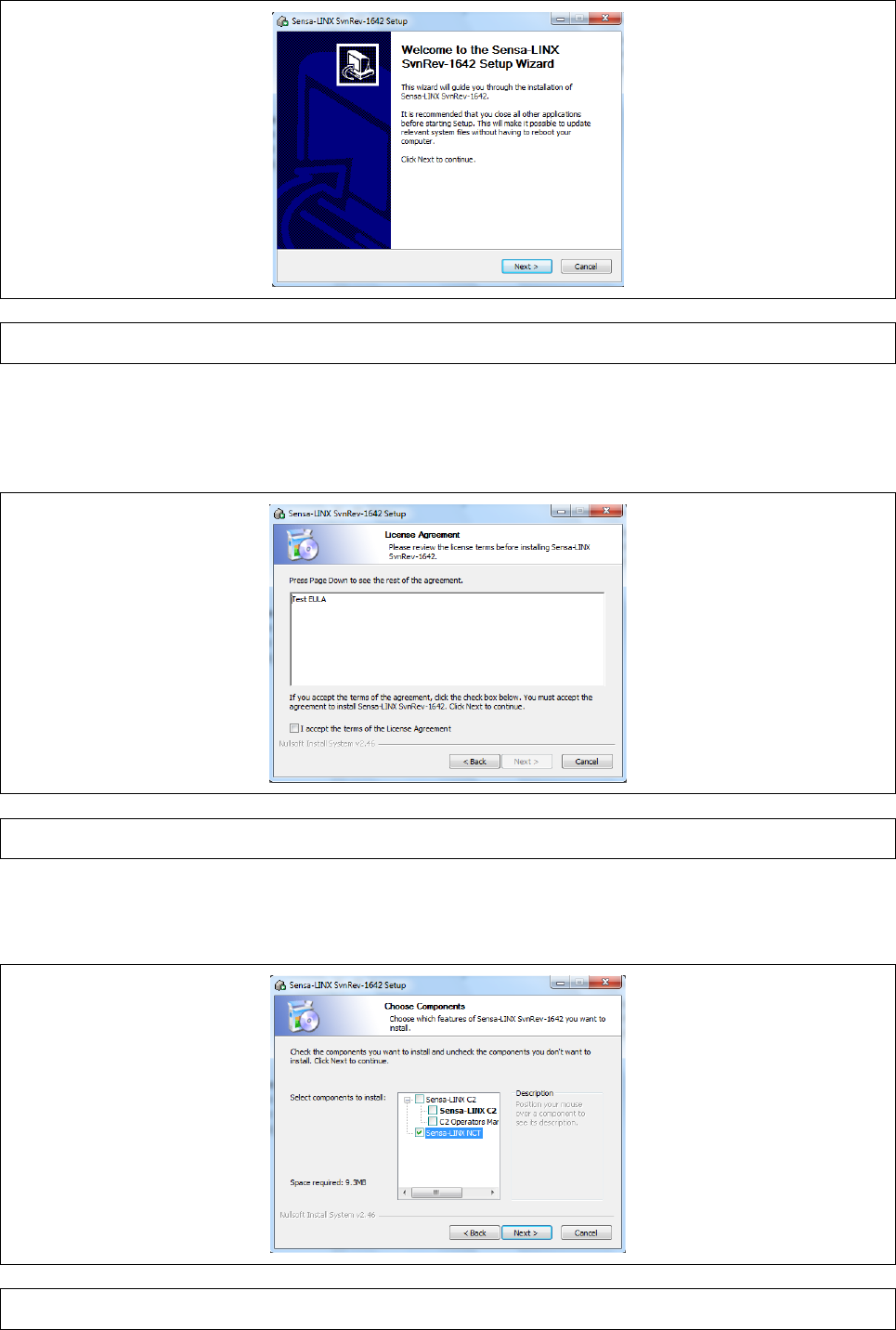
Appendix A
Page A-24
Figure 29 Installer welcome dialog
3 Read the license agreement. If you do not agree with all of the terms then click the Cancel
button. If you agree with the terms then check the “I accept the terms of the License
Agreement” check box. Click on the Next button to continue the installation.
Figure 30 Installer license agreement dialog
4 On the choose components screen, check the Sensa-LINX NCT check box and click the Next
button.
Figure 31 Installer choose components dialog
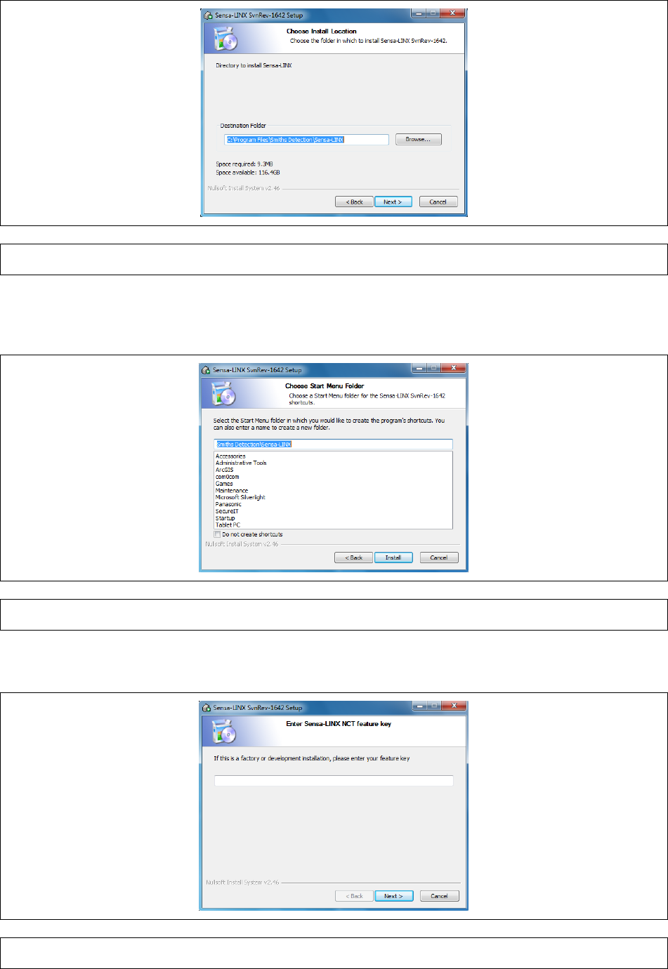
Appendix A
Page A-25
5 On the Choose Install Location screen, either accept the default folder or Browse to your
preferred folder. Click the Next button to continue.
Figure 32 Installer choose install location dialog
6 On the Choose Start Menu Folder screen, either accept the default or select a new start menu
folder. Click the Install button to continue.
Figure 33 Installer start menu folder dialog
7 On the feature key this field should be left blank. Click the Next button to continue.
Figure 34 Installer key option dialog
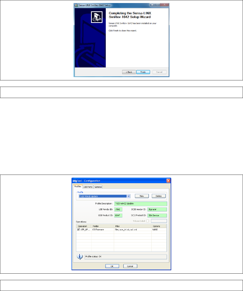
Appendix A
Page A-26
8 Click the Finish button to exit the installer
Figure 35 Installer setup complete dialog
9.4
CONFIGURING THE MANUFACTURING TOOL
This section describes the steps needed to configure the Manufacturing Tool. This configuration
has to be completed each time it is installed on a computer. However this configuration is only
required if you are going to use the NCT to load a new OS, load new software or download data log
files. If you are only going to use the tool to configure sensor node parameters then the remaining
steps can be omitted.
1 From the main screen of the MfgTool, select the OptionsConfiguration menu item. The dialog
shown in Figure 36 will be displayed
Figure 36 MfgTool Configuration Dialog
2 Select the ‘USB Ports’ tab and select a Hub and Port to use as shown in Figure 37. Refer to
paragraph 9.4.1 for detailed instructions on how to set up the USB ports.
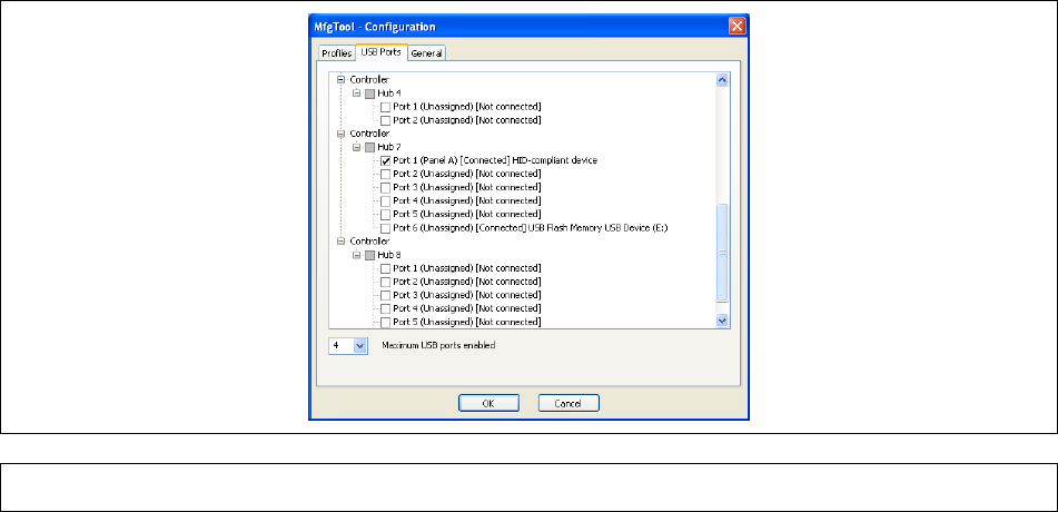
Appendix A
Page A-27
Figure 37 MfgTool USB Ports Dialog
3 Select a Port number as shown in Figure 37.
4 Click on the OK button and return to the Reprogramming Procedure.
9.4.1 USB PORTS TAB
Within the USB Ports tab, a visual representation of all the USB ports on the system is displayed.
When any USB device is attached to the computer, the device description will appear next to the
port node, and it will indicate Connected.
Up to sixteen (16) physical ports can be assigned for use during the manufacturing process. Use the
Maximum USB Ports control in the lower left portion of the window to define the maximum number of
USB ports to be used.
While selecting ports, after the maximum defined ports are selected, the rest of the checkboxes will
gray out indicating that no more ports are available. The Panels are assigned in alphabetical order.
Given that all Panels are unassigned, the first USB port checked will be assigned to Panel A, the
second port checked will be assigned to Panel B, etc. If some Panels are already assigned, the next
checked port will be assigned to the first available Panel alphabetically.
Select the physical ports that are to be used during the manufacturing process. When a port is
selected, the name of the associated (assigned) Panel will appear next to the port node. The
operation panels (A, B, C, and D) in the main application window correspond to the four physically
assigned ports shown in Figure 37.
Do not add or remove USB hubs from the system once the Operations Panels are assigned to
USB ports.
It is recommended that the user label each of the physical hub ports with the corresponding
Panel letter to facilitate the cycling of devices though the process.
The Start button in the main application window will not be enabled unless at least one USB
port is assigned to a panel.
Note: For more detailed information on setting up the USB ports, refer to the Freescale
Manufacturing Tool User Manual that is installed as part of the NCT installation.
Appendix A
Page A-28
This page is intentionally left blank