Snapper 130887660 User Manual SNOW THROWER Manuals And Guides L0910289
SNAPPER Snowthrower, Gas Manual L0910289 SNAPPER Snowthrower, Gas Owner's Manual, SNAPPER Snowthrower, Gas installation guides
User Manual: Snapper 130887660 130887660 SNAPPER SNOW THROWER - Manuals and Guides View the owners manual for your SNAPPER SNOW THROWER #130887660. Home:Lawn & Garden Parts:Snapper Parts:Snapper SNOW THROWER Manual
Open the PDF directly: View PDF ![]() .
.
Page Count: 36
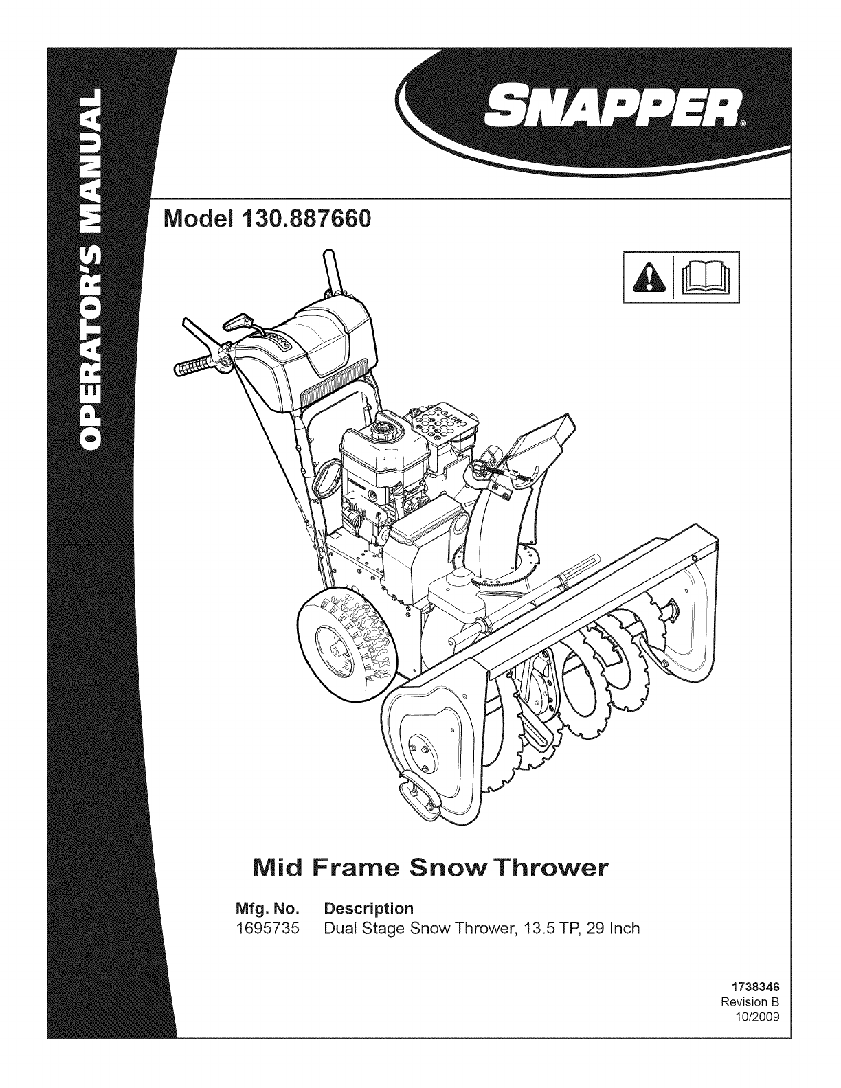
Model 130.887660
Mid
Mfg. No.
1695735
Frame Snow Thrower
Description
Dual Stage Snow Thrower, 13.5 TP, 29 inch
1738348
Revision B
10/2009
Thankyou for purchasingthis quality-built Snappersnow thrower. We're pleasedthat you've placedyour confidence in the Snapper
brand. When operated and maintained according to the instructions in this manual,your Snapperproduct will provide many years of de-
pendableservice.
This manual containssafety information to makeyou aware of the hazardsand risks associatedwith snow throwers and how to avoid
them. This snow thrower is designed and intended only for snow throwing and is not intended for any other purpose, it is important that
you readand understandthese instructions throroughly before attempting to start or operatethis equipment. This snow thrower
requires final assembly beforeuse, Referto the Quck Start Guidefor instructions on final assembly procedures. Follow the instructions
completely. Save these instructionsfor future reference.
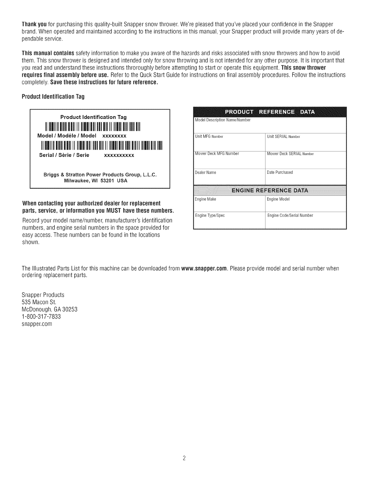
Product identificationTag
Product Identification Tag
Ill IIIIIII IIiil lllll Ilill lllll
Model /Modele/Model ××××××××
III lllllil Ilill lllll Illll IIIIIIlill III
Serial /Serie /Serie ××××××××××
Briggs & Stratton Power Products Group, L.L.C.
Milwaukee, WI 53201 USA
When contactingyour authorized dealer for replacement
parts, service, or informationyou MUST have these numbers.
Recordyour model name/number,manufacturer's identification
numbers, and engine serial numbers in the space provided for
easyaccess. Thesenumbers can befound in the locations
shown.
Model Description Name/Number
Unit MFG Number
Mower Deck MFG Number
Dealer Name
Unit SERIAL Number
Mower Deck SERIAL Number
Date Purchased
Engine Make Engine Model
Engine Type/Spec Engine Code/Serial Number
The illustrated Parts List for this machinecan bedownloaded from www.snapper.corn. Pleaseprovide model and serial number when
ordering replacement parts.
Snapper Products
535 Macon St.
McDonough, GA30253
1-800-317-7833
snappencom
TABLEOFCONTENTS
OPERATORSAFETY.................................................................................... 4
FEATURESANDCONTROLS.......................................................................... 10
OPERATION............................................................................................. 12
BEFOREOPERATINGSNOWTHROWER...................................................................................................12
OPERATETHESNOWTHROWER..............................................................................................................12
STOPTHESNOWTHROWER....................................................................................................................13
WHEELLOCKOUTPIN..............................................................................................................................13
DISCHARGECHUTEANDDEFLECTOR....................................................................................................13
CHECKTHEOIL(BEFORESTARTINGENGINE)........................................................................................14
FILLTHEFUELTANK................................................................................................................................14
STARTTHEENGINE..................................................................................................................................15
STOPTHEENGINE....................................................................................................................................16
CLEARA CLOGGEDDISCHARGECHUTE.................................................................................................17
OPERATINGTIPS......................................................................................................................................17
MAINTENANCE......................................................................................... 18
SERVICERECOMMENDATIONS...............................................................................................................18
LUBRICATEAUGERGEARBOX.................................................................................................................19
LUBRICATEAUGERSHAFTFITTINGS......................................................................................................19
LUBRICATECONTROLLEVERLINKAGE...................................................................................................19
LUBRICATEDISCHARGECHUTEANDDEFLECTOR.................................................................................19
ENGINEMAINTENANCE...........................................................................................................................20
CHANGETHESPARKPLUG......................................................................................................................21
ADJUSTSKIDHEIGHT..............................................................................................................................22
BELTADJUSTMENT..................................................................................................................................23
BELTGUIDEADJUSTMENT......................................................................................................................23
SPEEDCONTROLRODADJUSTMENT.....................................................................................................24
CHECKANDADJUSTTHECABLES..........................................................................................................24
AUGERCONTROLCABLEADJUSTMENT.................................................................................................24
TRACTIONCONTROLCABLEADJUSTMENT...........................................................................................25
CHUTEROTATIONMOTORADJUSTMENT...............................................................................................26
AUGERSHEARPINREPLACEMENT.........................................................................................................26
CHECKTHETIRES....................................................................................................................................27
STORAGE................................................................................................ 28
OFFSEASONSTORAGE............................................................................................................................28
LUBRICATEHEXSHAFTANDCHAINS.....................................................................................................28
REMOVEFROMSTORAGE........................................................................................................................28
TROUBLESHOOTING................................................................................... 29
WARRANTIES........................................................................................... 31
SPECIFICATIONS....................................................................................... 33
OPERATORSAFETY
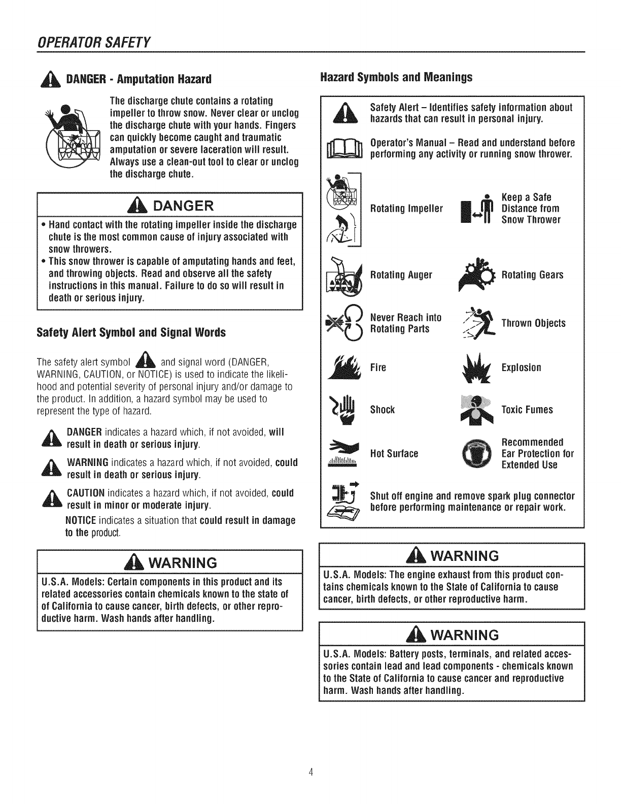
,t_ DAHGER- Amputation Hazard
The dischargechutecontainsarotating
impeller to throwsnow. Never clear or unclog
the dischargechutewith your hands.Fingers
can quickly becomecaughtand traumatic
amputation or severe lacerationwill result.
Alwaysuseaclean-outtool to clear or unclog
the dischargechute.
DANGER
,, Hand contactwith the rotating impeller insidethe discharge
chuteis the most commoncause of injury associated with
snowthrowers.
,, Thissnowthrower is capable of amputating handsand feet,
and throwingobjects. Read and observeall the safety
instructionsin this manual. Failure to do so will result in
deathor serious injury.
SafetyAlert Symboland SignalWords
,&
The safety alert symbol _ and signal word (DANGER,
WARNING,CAUTION,or NOTICE)is used to indicate the likeli-
hood and potential severity of personal injuryand/or damage to
the product. In addition, a hazardsymbol may be used to
represent the type of hazard.
,ll_ DANGERindicates a hazard which, if not avoided,will
result in death or serious injury.
_ ARNINGindicates a hazardwhich, if not avoided, could
result in death or serious injury.
,i_ CAUTIONindicates a hazardwhich, if not avoided,could
result in minor or moderate injury.
NOTICEindicates a situation that couldresult in damage
to the product.
WARNING
U.S.A. Models: Certain componentsinthis productand its
related accessories containchemicalsknown to the state of
of California to causecancer,birth defects, or other repro-
ductive harm. Wash hands after handing.
Hazard Symbols and Meanings
t_
ti_L,,,;_. I
Safety Alert -Identifies safety informationabout
hazardsthat can result in personal injury.
Operator's Manual- Read and understand before
performingany activity or running snow thrower.
Rotating Impeller •Keepa Safe
Distance from
Snow Thrower
Rotating Auger
Never Reach into
Rotating Parts
_ Rotating Gears
t_,_ Thrown Objects
Fire Explosion
Shock ToxicFumes
HotSurface Recommended
Ear Protection for
ExtendedUse
Shut off engine and remove sparkplug connector
beforeperformingmaintenance or repairwork.
WARNING
U.S.A. Models: The engine exhaust from this productcon-
rains chemicalsknown to the State of California to cause
cancer, birthdefects, or other reproductiveharm.
WARNING
U.S.A. Models: Batteryposts,terminals, and related acces-
sories containlead and lead components- chemicalsknown
to the State of California to causecancerand reproductive
harm. Wash hands after handing.
OPERATORSAFETY
Control Symbols on Equipment
._ Fuel
On Off
J+J Choke 0ff
I' 1°"°"°°°
Stop
Slow
]=p-_
R1--
Forward
Neutral
Reverse
ElectricStart -
Engage(Down) &
Disengage (Up)
Engine- Run
w
m_,a
m
Fast
TractionControl -
Engage(Down)
AugerClutch
[_ ischargeChute
(Left and Right)
I w
=_'-m
-dr
Engine -Stop
AugerControl -
Engage (Down)
Chute Deflector
(Up and Down)
Heated HandGrips
(High and Low)
Easy-TurnTM TractionControl TM
Free-Hand Control
Readthe Manual
DANGER
Read,understand,andfollowall theinstructionsonthe
snowthrowerandintheoperator'smanualbeforeoperating
this unit.
Failuretoobservethesafetyinstructionsinthismanualwill
resultindeathorseriousinjury.
o Bethoroughlyfamiliarwith thecontrolsandtheproperuseofthesnow
thrower.
,, Makesureyouareproperlytrainedbeforeoperatingthesnowthrower.
,, Knowhowto stoptheunit anddisengagethecontrolsquickly.
,, Neverallowanyoneto operatethesnowthrowerwithoutproperinstruction.
,, Alwaysfollow theinstructionsin theoperator'smanual,if thesnowthrower
will bestoredfor anextendedperiod.
,, Maintainor replacesafetyandinstructionlabelsasnecessary.
,, Neverattemptto makemajorrepairson thesnowthrowerunlessyou have
beenproperlytrained.Improperservicingof thesnowthrowercan result
in hazardousoperation,equipmentdamage,andvoidingof theproduct
warranty.
Discharge Chute
DANGER
Dischargechutecontainsrotatingimpellerto throwsnow.
Neverclearorunclogthedischargechutewithyourhands.
Fingerscanquicklybecomecaughtintheimpeller.Always
useaclean-outtool.
Failureto observethesesafetyinstructionswill resultin
traumaticamputationorseverelaceration.
TOSAFELYCLEARA CLOGGEDDISCHARGECHUTE
,_ DANGER:Handcontactwiththerotatingimpellerinsidethedischarge
chuteis themostcommoncauseof injuryassociatedwithsnow
throwers.Neveruseyourhandstocleanoutthedischargechute.
FOLLOWTHESEINSTRUCTIONS:
1. ShutOFFtheengine.
2.Wait10secondstobesuretheimpellerbladeshavestoppedrotating.
3.Alwaysuseaclean-outtool,notyourhands.
NOTE:Hot all control symbolsshown on this pagewill appear
onyour snowthrower.See FEATURESAND CONTROLSsection
for the applicablesymbols.
OPERATORSAFETY
Operationand EquipmentSafety
DANGER
Thissnowthroweris onlyassafeas theoperator.If it is
misused,or notproperlymaintained,it canbedangerous.
]Rememberyouareresponsiblefor yoursafetyandthatof
thosearoundyou.
*Keeptheareaof operationclearof all persons,particularlysmallchildren
andpets.
. Thoroughlyinspecttheareawherethesnowthrowerwill beusedandremove
all doormats,sleds,boards,wires,andotherforeignobjects.
. Do notoperatethesnowthrowerwithoutwearingadequatewinterclothing.
. Wearfootwearthatwill improvefootingonslipperysurfaces.
. Usecautionto avoid slippingorfalling especiallywhenoperatingthe
snowthrowerin reverse.
*, Neveroperatethesnowthrowerwithoutgoodvisibility or light.Alwaysbe
sureof yourfooting,andkeepafirm holdon thehandles.
. Do notclearsnowacrossthefaceof slopes.Useextremecautionwhen
changingdirectiononslopes.Donotattemptto clearsteepslopes.
. Do notoverloadthemachinecapacitybyattemptingto clearsnowtoo
quickly.
. Neveroperatethesnowthrowerat hightransportspeedsonslippery
surfaces.Lookbehindthesnowthrowerandusecarewhenoperatingin
reverse.
o Do notusethesnowthroweron surfacesabovegroundlevelsuchas roofsof
residences,garages,porches,or othersuchstructuresor buildings.
*Operatorsshouldevaluatetheirabilityto operatethesnowthrowersafely
enoughto protectthemselvesandothersfrom injury.
. Thesnowthroweris intendedto removesnowonly. Donotusethesnow
throwerforanyotherpurpose.
. Do notcarrypassengers.
*, Afterstrikinga foreignobject,shutOFFtheengine,disconnectthecordon
electricmotors,thoroughlyinspectthesnowthrowerfor anydamage,and
repairthedamagebeforerestartingandoperatingthesnowthrower.
*, If thesnowthrowervibratesabnormally,shutOFFtheengine.Vibrationis
generallyawarningof trouble.Seeanauthorizeddealerif necessaryfor
repairs.
. Formodelsequippedwithelectricstartingmotors,disconnectthepower
cordaftertheenginestarts.
FuelHandling
DANGER
Fuelanditsvaporsareextremelyflammableandexplosive,
Alwayshandlefuelwithextremecare.
Failureto observethesesafetyinstructionscancausea fire
Ior explosionwhichwill resultin severeburnsor death.
WHENADDINGFUEL
*Turnoff engineandletcool at least2 minutesbeforeremovingthefuel
capandaddingfuel.
o Fill fueltankoutdoorsor in awell ventilatedarea.
o Donotoverfillthefuel tank.Toallowfor theexpansionof gasoline,do notfill
abovethebottomof thefuel tankneck.
o Keepfuel awayfromsparks,openflames,pilot lights, heat,andother
ignitionsources.
o Checkfuel lines,cap,andfittingsfrequentlyfor cracksor leaks.Replaceif
necessary.
o Useanapprovedfuelcontainer.
o If fuelspills,wait until it evaporatesbeforestartingengine.
WHENSTARTINGENGINE
*, Ensurethatsparkplug, muffler,fuelcap,andair cleaner(if equipped)are in
placeandsecured.
. Donotcranktheenginewiththesparkplug removed.
. If fuel isspilled,do notattemptto starttheengine,butmovethesnow
throwerawayfrom theareaof thespill, andavoidcreatinganysourceof
ignition,until thefuelvaporshavedissipated.
*, Donotover-primetheengine.Followtheenginestartinginstructionsin this
manual.
. If theenginefloods,setchoke(if equipped)to OPEN/RUNposition,move
throttle(if equipped)to FASTpositionandcrankuntil enginestarts.
WHENOPERATINGEQUIPMENT
*Donottip thesnowthrowerat ananglewhichcausesthefuelto spill.
o Donotchokethecarburetorto stoptheengine.
o Neverruntheenginewiththeaircleanerassembly(if equipped)or theair
filter (if equipped)removed.
WHENCHANGINGOiL
*If youdraintheoilfromthetopoil fill tube,thefuel tankmustbeemptyor
fuelcanleakoutandresultin afire orexplosion.
IWHENTRANSPORTINGEQUIPMENT
*, TransportwithfueltankEMPTY,orwithfuelshut-offvalveOFE
IWNENSTORINGGASOLINEOREQUIPMENTWiTHFUELiN TANK
*, Storeawayfromfurnaces,stoves,waterheaters,or otherappliancesthathave
pilot light or otherignitionsourcebecausetheycanignitefuelvapors.
OPERATORSAFETY
Moving Parts
DANGER
Keephands,feet,andclothingawayfromrotatingparts.
Rotatingpartscancontactorentanglehands,feet,hair,
clothing,oraccessories.
Failuretoobservethesesafetyinstructionswill resultin
traumaticamputationorseverelaceration.
=Whenevercleaning,repairing,or inspectingthesnowthrower,makesurethe
engineis OFF,sparkplugwireisdisconnected,andallmovingpartshave
stopped.
. Donotputhandsorfeetnearor underrotatingparts.Keepclearofthe
dischargeopeningat alltimes.
. Neveroperatethesnowthrowerwithoutproperguards,andothersafety
devicesin placeandworking.
. Neverleavethesnowthrowerunattendedwhileengineis running.Always
disengagetheaugerandtractioncontrols,stopengine,andremovekeys.
. Keepall looseclothingawayfromthefrontof thesnowthrowerandauger.
Scarves,mittens,danglingdrawstrings,looseclothes,andpantscanquickly
becomecaughtin therotatingdeviceandamputationwill occur.Tieup
longhairandremovejewelry.
. Runthemachineafewminutesafterdischargingsnowto preventfreeze-up
of thecollector/impeller.
. Disengagepowerto the collector/impellerwhensnowthroweristransported
or notin use.
Thrown Objects
DANGER
Objectscanbepickedupbyaugerandthrownfromchute.
Neverdischargesnowtowardbystandersorallowanyonein
frontofthesnowthrower.Failureto observethesesafety
instructionswillresultindeathorseriousinjury.
o Alwayswearsafetyglassesor eyeshieldswhileduringoperation,andwhile
performinganadjustmentor repair.
o Alwaysbeawareof thedirectionthe snowis beingthrown.Nearby
pedestrians,pets,or propertymaybeharmedby objectsbeingthrown.
o Beawareof yourenvironmentwhileoperatingthesnowthrower.Running
overitemssuchas,gravel,doormats,newspapers,toys,androckshidden
undersnow,canall bethrownfromthechuteor jamintheauger.
o Useextremecautionwhenoperatingon or crossinggraveldrives,walks,or
roads.
o Adjustthecollectorhousingheightto cleargravelorcrushedrocksurface.
o Neveroperatethesnowthrowernearglassenclosures,automobiles,window
wells,drop-otis,andthe likewithoutproperadjustmentof thedischarge
chuteangle.
o Familiarizeyourselfwiththeareain whichyouplanto operatethesnow
thrower.Markoffboundariesof walkwaysanddriveways.
Children
DANGER
Tragicaccidentscanoccurif theoperatoris notalertto the
presenceof children,Childrenareoftenattractedto theunit
andtheoperatingactivity.Neverassumethatchildrenwill
remainwhereyoulastsawthem.
o Keepchildrenout of theareaduringoperation.Childrenareoftenattractedto
theequipment.Bemindfulof all personspresent.
. Bealertandturn unit offif childrenenterthearea.
. Neverallowchildrento operatetheunit.
. Useextracarewhenapproachingblindcorners,shrubs,trees,or other
objectsthatmayobscurevision.Childrenmaybepresent.
Engine Safety
DANGER
I Safeoperationof thesnowthrowerrequiresthepropercare
_ and maintenanceof theengine.Failureto observethe safety
instructionsin this manualwill result in deathor serious
injury.
. Disengageallclutchesandshift intoneutralbeforestartingtheengine.
. Lettheengineadjustto outdoortemperaturesbeforestartingto clearsnow.
. Usea groundedthree-wireplug-infor all snowthrowersequippedwith
electricdrivemotorsor electricstartingmotors.
DANGER
Enginesgiveoff carbonmonoxide,an odorless,colorless,
poisongas.
Breathingcarbonmonoxidecancausenausea,hinting,
or death.
*Startandrun engineoutdoors.
Donotruntheenginein anenclosedarea,evenif doorsorwindowsare
open.
OPERATORSAFETY
Engine Safety (Continued)
WARNING
jStartingenginecreatessparking.
jSparkingcanignitenearbyflammablegases.
Explosionandfire couldresult.
*Ifthereisnaturalor LPgasleakagein area,do notstartengine.
,, Donotusepressurizedstartingfluids becausevaporsareflammable.
WARNING
,_l_((l(I}(_(ll,, Runningthe engineproducesheat.Enginepan, especially
i muffler,becomeextremelyhot.
Failureto observethesesafetyinstructionscould result in
i severethermalburnsoncontact.
*Nevertoucha hotengineormuffler.Allow muffler,enginecylinder,andfins
to coolbeforetouching.
,, Removedebrisfrommufflerareaandcylinderarea.
,, Installandmaintaininworkingorderasparkarresterbeforeusingequipment
onforest-covered,grass-covered,orbrush-coveredunimprovedland.
,, U.S.A.Models:It is a violationof CaliforniaPublicResourceCode
Section4442to useor operatetheengineonor nearanyforest-covered,
brush-covered,or grass-coveredlandunlesstheexhaustsystemis equipped
with asparkarrestermeetinganyapplicablelocalor statelaws.Otherstates
orfederalareasmayhavesimilarlaws.
Maintenanceand Storage
WARNING
Thissnowthrowermustbeproperlymaintainedto ensuresafe
operationand performance.Failure to observethe safety
instructionsin this manualcould resultin deathor serious
injury.
*Whenperforminganymaintenanceor repairson thesnowthrower,shutOFF
theengine,disconnectsparkplugwire,andkeepthewire awayfromthe
plugto preventsomeonefromaccidentlystartingtheengine.
,, Checkshearboltsandotherhardwareatfrequentintervalsfor proper
tightnessto besurethesnowthroweris in safeworkingcondition.
,, Keepnutsandboltstight andkeepsnowthrowerin goodcondition.
,, Nevertamperwith safetydevices.Checktheir properoperationregularlyand
makenecessaryrepairsif theyarenotfunctioningproperly.
,, Componentsaresubjectto wear,damage,anddeterioration.Frequently
checkcomponentsandreplacewith recommendedparts,whennecessary.
,, Checkcontroloperationfrequently.Adjustandserviceas required.
,, Useonly factoryauthorizedreplacementpartswhenmakingrepairs.
,, Alwayscomplywithfactoryspecificationsonall settingsandadjustments.
,, Onlyauthorizedservicelocationsshouldbeutilizedfor majorserviceand
repairrequirements.
,, Useonly attachmentsandaccessoriesapprovedby thefactory(suchas
wheelweights,counterweights,or cabs).
,, Neverattemptto makeanyadjustmentswhiletheengineis running(except
whenspecificallyrecommendedbythefactory).
OPERATORSAFETY
Lookfor this symboJto indicateimportantsafety
precautions.This symbolindicates:"Attention!
Become Alert! YourSafety is At Risk."
Before operating your snow thrower, readthe safetydecals
as shownon yoursnowthrower.The cautionsand warnings
are for yoursafety. To avoid a personalinjuryor damageto
yoursnow thrower, understandand follow all the safety decals.
WARNING:Ifanysafetydecalsbecomewornordamagedand J
cannotberead,orderreplacementdecalsfromyour localdealer. I
Part No. 1738349
Shift Decal
Part No. 1737870
TractionControlDecal
Part No. 1737869
AugerControlDecal
EngineDecals
Part No. 278297
_AMILY×XX××,X×XXX× X×XXX×
Part No. 277953
Part No. 1737875
Main DashDecal
Amputation hazard/Ji=
Contact with m_ving pa_ts taside "_
chute wig cause serious tntury.
Shut off engine heto_e uncloggtag
discharge chute.
• Use clean-out tool not hands!
Risque d'amputation
Tout contact avec des pi_ces en mouvement _ r tat_deut
de la geulotta provoquera de graves b_esse_es.
• Arr_tar le _qotaur avant de d_gager Ja goulefle
d'djecttan.
•Utiliser Foutil de dggagement, gas les matas_
Part No. 1737865
ChuteDanger Decal
ProductID Humber&
Serial HumberDecal
(Rearof Motor Box) Amputation Hazard Risque d'amputation
•ceet_t wg_ a_ger wgz •xo_t contac_ _vec Ja
cause serious injury, t_ri_re provo_er_ de
•Keep hands, _eel and graves htassures.
clothing _way. *Tenir yes prods, yes mains
• Keep hyst_n_e_ _way. et vgteme.ts dDistance.
•Tenir tas spectateurs
Thrown Objects Danger objets projet_g
Hazard • Ne lamtas dlflget ta
• Never dffect discharge o_e en di_ectta_ des
...........ch........ ds p...... _ _i!enlnPea__g,; en_sS.o. biens
Read the operator's
m_n_al tar operattag and
safeIy taslructta_s. _e man_eJ d'_tg_safiolt.
Shut off engine and Arrg_er Je moleur et
remove hey before rotifer ta cta avast
.............perramming mataten_nce _ _2iiil°eiieng'eflect_e_tout e_ffettan
Part No. 1737866
AugerDanger Decal
Safety Decals Figure
FEATURESANDCONTROLS
NOTICE:ReadthisOPERATOR'SMANUALand OPERATORSAFETYbefore operatingyoursnowthrower. Comparethe illustrationswithyour
SNOWTHROWERto familiarize yourselfwiththe locationof variouscontrolsand adjustments.Savethismanual for future reference.
/
®
®
®
EngineControls Figure 2
ENGINEANDSNOWTHROWERCONTROLS
ENGINECONTROLS
A. Choke Control Knob-- Usedto startacold engine(seeFigure2).
B. ElectricStart Button-- Usedto starttheengineusingtheelectric
starter.
C. Primer Button-- Usedto injectfueldirectlyintothecarburetor
manifoldto ensurefaststartsin coolweather.
D. Safety Key-- Mustbeinsertedto startengine.Pullout to stop.Do
notturnsafetykey.
E. Starter CordHandle-- Usedto starttheenginemanually.
F. ON/OFFSwitch -- Usedto startandstoptheengine.
G. Fuel Tankand Cap-- Fill thefueltankto approximately1-1/2 in.
(38mm)belowthetopof theneckto allowfor fuelexpansion.
H. 0il Fill Cap (Extended Dipstick)
SNOWTHROWERCONTROLS
A. SpeedSelect Lever-- Allowstheoperatorto useoneof six(6)
forwardandtwo(2)reversespeeds(seeFigure3). Toshift,move
speedselectleverto desiredposition.
NOTICE:Do not move speedselect lever while Traction
Control is engaged. This may result in severe damage
to the drivesystem.
10
FEATURESANDCONTROL$
®
®
®
®
w
®
®
SnowThrowerControls
B. Auger Control Lever-- Usedto engageanddisengagethe
augerandimpeller.Toengagepushdown,to disengagerelease.
C. Chute RotationSwitch-- Usedto rotatethedischargechute
to theleftor right.
D. Chute DeflectorSwitch-- Usedto controltheangleof thechute
deflector(upor down).
E. Free-HandTM Control -- Afterengagingthetractioncontrol(left
hand)andaugercontrol(righthand),allowstheoperatorto
releasetheaugercontrolleverto usetheothercontrols.
Figure3
F. TractionControlLever-- Usedto propelsnowthrowerfor-
wardor reverse.Pushdownto engage,releaseto disengage.
G. Clean-Out Tool -- Usedto removesnowanddebrisfromthedis-
chargechuteandthe augerhousing.
HSkid Shoe-- Usedto adjustthegroundclearanceof theauger
housing.
11
OPERATION
BEFOREOPERATINGSNOWTHROWER
Checkthefasteners.Makesureall fastenersaretight.
Onelectric start models,the unit wasshippedwith the startercord
pluggedintotheengine.Beforeoperating,unplugthestartercordfromthe
engine.
NOTE: This snow thrower was shipped WITH OiL in the
engine. See "Before Starting Engine" instructions in the
OPERATIONsection of this manuaJ before startingengine.
WARNING:The operation of any snow throwercan result in foreign objects beingthrowninto the eyes, which can result in
severe eye damage. Always wear safety glasses or eye shields before beginning snow throweroperation. We recommend
standard safety glasses or Wide Vision Safety Mask over spectacles.
OPERATETHE SNOW THROWER
dl_ CAUTION:Operation with a Snow Cab. Wind may blow
exhaust gasses backtowardsthe operator, if you notice
the smell of exhaust, changedirection of operation.
NOTICE:Do not throwsnow toward a buiJding as hiddenobjects
couldbe thrownwith sufficientforce to causedamage.
1. Starttheengine.See"ToStartEngine"inthis section. 5.
2. Pressthechuterotationswitch(A, Figure4)to theUP/DOWNposition
to rotatethedischargechuteleftorright.See"DischargeChuteand
Deflector"in thissection. 6.
3. Pushthechutedeflectorswitch(B)to the UP/DOWNpositionto
controltheangleof thechutedeflector.See"DischargeChuteand
Deflector"in thissection.
Free-HandTM Control
CAUTION:Before operating, makesurethe area in
front of the snow throweris cJearof bystandersor
obstacJes.
4. Fullypressandholdtheaugercontrollever(C)to engageauger
rotation.Releasingtheaugercontrolleverwill disengagetheauger-
unlessthe Free-HandTM controlhasbeenactivated.
FullypressandholdthetractionandFree-HandTM controllever(D)to
engagethetractiondriveandbeginmovingthesnowthrower.Todis-
engagethetractiondrive,completelyreleasethelever.
WhenBOTHleversaredepressed,theFree-HandTM controlis acti-
vated.Thisallowsaugercontrolleverto bereleased- YETAUGER
ROTATIONWILLCONTINUE- untiltheFree-HandTM controlis re-
leased.
NOTE:Always reJeasethe tractioncontrollever before moving
the speed select lever.
7. Usethespeedselectlever(E)to selecttheforwarddrivespeed.Setthe
speedselectleverto oneof thefollowingpositionsasdeterminedby
snowconditions:
1-2 Wet,Heavy,Slushy,ExtraDeep
3 Moderate
4-5 VeryLight
6 Transport
NOTE: When clearingwet, heavy,snow, it is recommended
that the ground speedof the unit be reduced, maintained fnlJ
throttleand do notattempt to clear the fuji width of the unit.
8. Tostopmovingforward,releasethetractioncontrollever(D).
9. Tomovethesnowthrowerbackwards,movethespeedselectleverinto
eitherfirst orsecondreversepositionandengagethetractioncontrol
lever.
Control Levers Figure 4
12
OPERATION
STOPTHESHOWTHROWER
1. Releasetheaugercontrollever(C,Figure4).
2. Releasethetractioncontrollever(D).
3. PushtheON/OFFswitch(A, Figure12)totheOFFpositionandpull
outthesafetykey(B).
WARNING:Never run engine indoorsor in an enclosed,
poorventilatedarea. EngineexhaustcontainsCARBON
MONOXIDE,an ODORLESSand DEADLYGAS.
,, Keephands,feet, hair, and loose clothingaway
from any moving parts on engineand snow
thrower.
,, Temperatureof muffler and nearby areas can
exceed 150°F (66°C). Avoidthese areas.
,, DO NOTallow childrenor youngteenagers to
operate or be near snowthrower while it is
operating.
WARNING:Read Operator's Manual before operating
machine.This machine can be dangerousif used
carelessly.
,, Never operatethe snowthrower without all guards,
covers, shields in place.
,, Never direct dischargetowards windows or allow
bystandersnear machine while engine is
running.
,, Stopthe engine whenever leaving the operating
position.
• Disconnectspark plugbefore unclogging the
impeller housingor the dischargechuteand
before making repairsor adjustments.
,, Whenleaving the machine, remove the safetykey.
Toreducethe riskof fire, keep the machine clean
and free from spilledgas, oil, and debris.
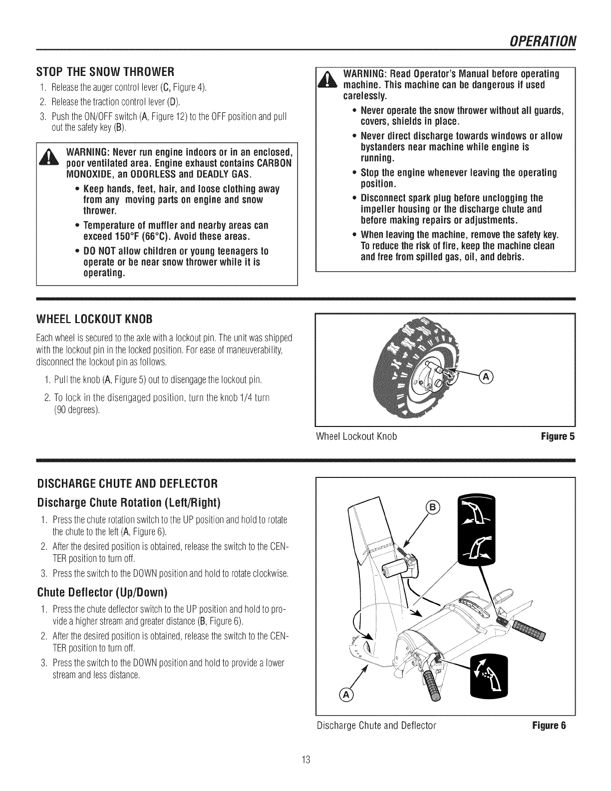
WHEELLOCKOUTKNOB
Eachwheelis securedto theaxlewitha lockoutpin.Theunitwasshipped
withthe lockoutpin inthelockedposition.Foreaseof maneuverability,
disconnectthelockoutpinasfollows.
1. Pulltheknob(A, Figure5)out to disengagethelockoutpin.
2. To lock in the disengagedposition, turn the knob1/4 turn
(90degrees).
Wheel Lockout Knob Figure 5
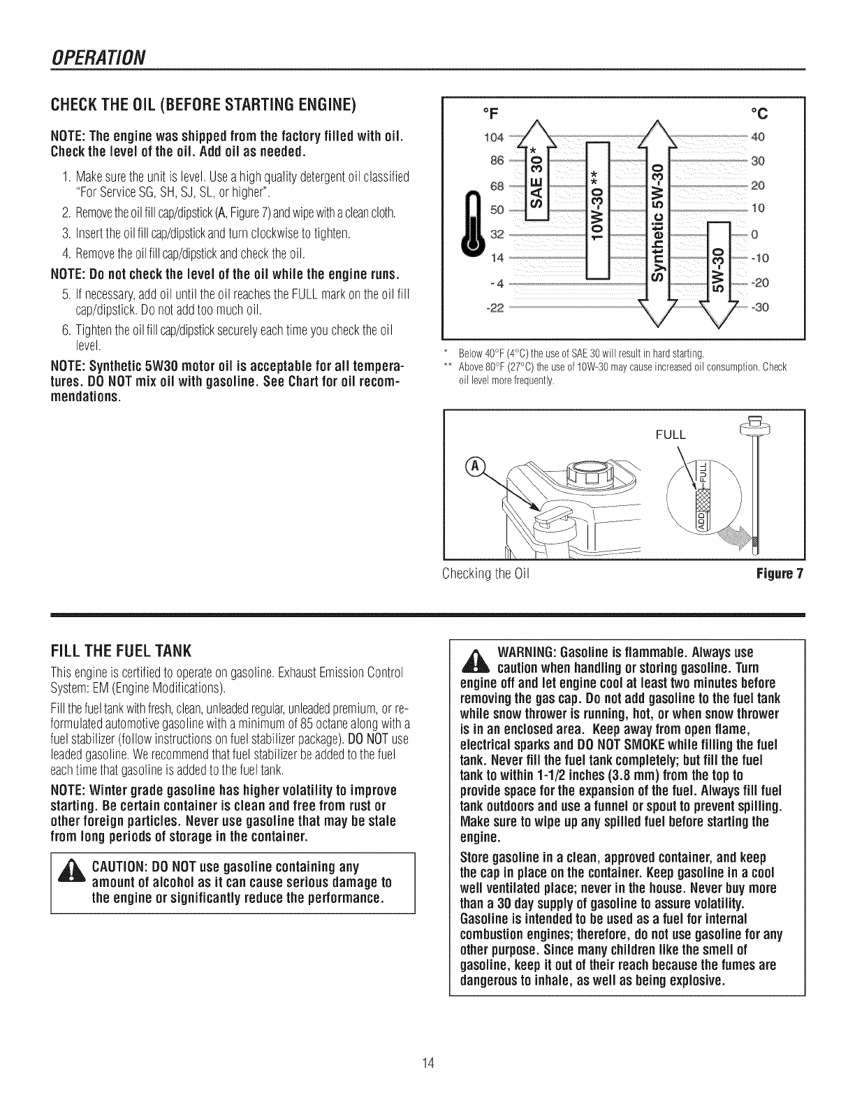
DISCHARGECHUTEANDDEFLECTOR
Discharge Chute Rotation (Left/Right)
1. Pressthechuterotationswitchto theUPpositionandholdto rotate
thechuteto theleft(A,Figure6).
2. Afterthedesiredpositionis obtained,releasetheswitchto theCEN-
TERpositionto turnoff.
3. Presstheswitchto theDOWNpositionandholdto rotateclockwise.
ChuteDeflector(Up/Down)
1. Pressthechutedeflectorswitchto theUPpositionandholdto pro-
videa higherstreamandgreaterdistance(B,Figure6).
2. Afterthedesiredpositionis obtained,releasetheswitchto theCEN-
TERpositionto turnoff.
3. Presstheswitchto theDOWNpositionandholdto providea lower
streamandlessdistance.
Discharge Chuteand Deflector Figure6
13
OPERATION
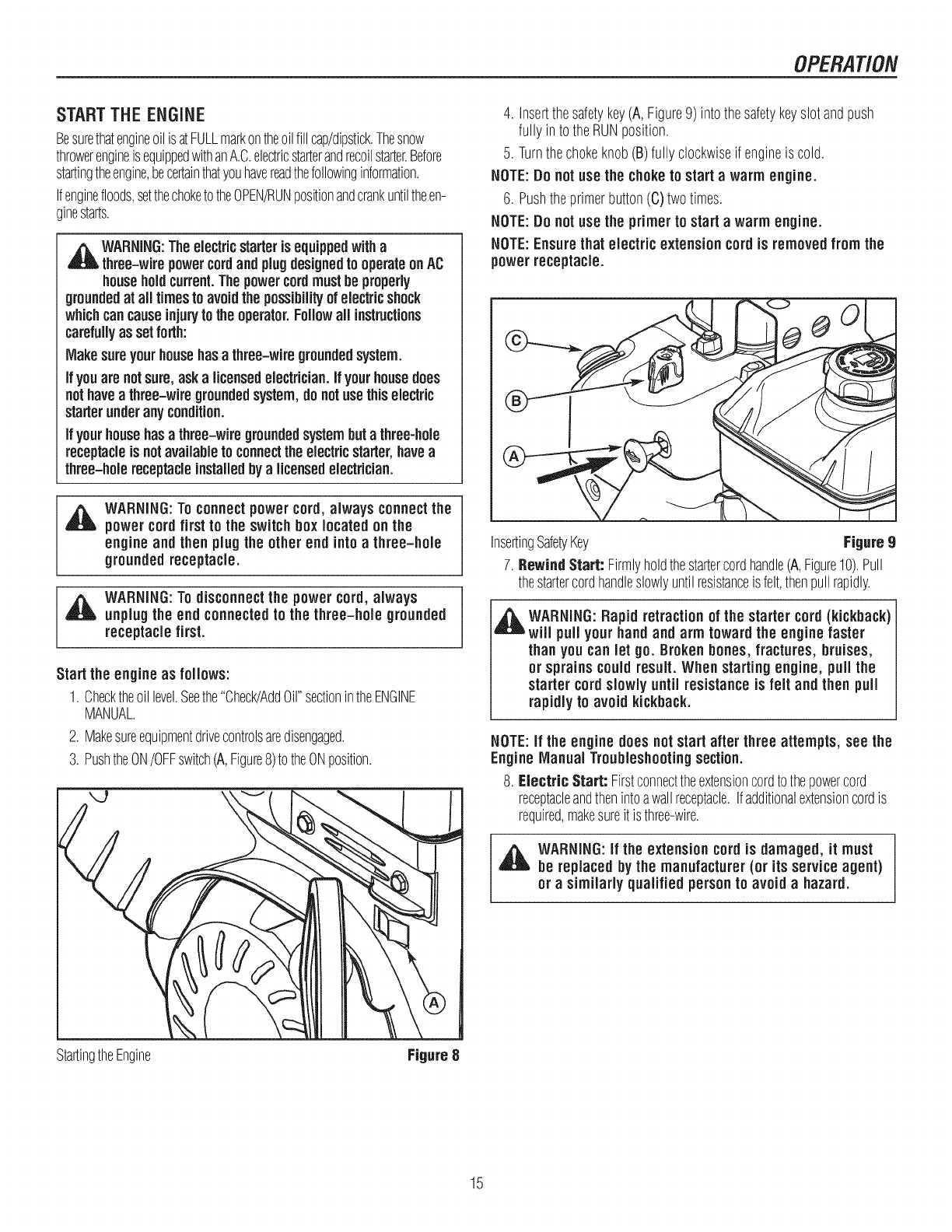
CHECKTHE OiL (BEFORE STARTING ENGINE)
NOTE:The enginewas shipped from the factory filled with oil.
Check the level of the oil. Add oil as needed.
1. Makesuretheunit is level.Useahighqualitydetergentoil classified
"ForServiceSG,SH,SJ, SL,or higher".
2. Removetheoilfill cap/dipstick(A,Figure7)andwipewithacleancloth.
3. Inserttheoilfill cap/dipstickandturn clockwisetotighten.
4. Removetheoilfill cap/dipstickandchecktheoil.
NOTE:Donot checkthe level of the oil while the engine runs.
5. If necessary,addoil untiltheoil reachestheFULLmarkontheoil fill
cap/dipstick.Donotaddtoo muchoil.
6. Tightentheoilfillcap/dipsticksecurelyeachtimeyouchecktheoil
level.
NOTE:Synthetic 5W30 motor oil is acceptable for all tempera-
tures. DONOTmix oil with gasoline. See Chart for oil recom-
mendations.
oF
i 04
68 0
5o
i 32
14
o4
°22
°C
Below40°F(4°C)the useofSAE30will resultin hardstarling.
** Above80°F (27°C)the useof 10W-30maycauseincreasedoil consumption.Check
oil levelmorefrequently.
FULL
Checkingthe Oil Figure 7
FiLL THE FUEL TANK
Thisengineis certifiedto operateongasoline.ExhaustEmissionControl
System:EM(EngineModifications).
Fillthefueltankwithfresh,clean,unleadedregular,unleadedpremium,orre-
formulatedautomotivegasolinewitha minimumof 85octanealongwitha
fuelstabilizer(followinstructionsonfuelstabilizerpackage).DONOTuse
leadedgasoline.Werecommendthatfuelstabilizerbeaddedto thefuel
eachtimethatgasolineis addedtothefueltank.
NOTE:Winter grade gasoline has highervolatility to improve
starting. Be certain containeris clean and free from rustor
other foreign particles. Never use gasoline that may be stale
from longperiodsof storagein the container.
_IL AUTION:DO NOTuse gasoline containingany
amountof alcohol as it cancauseseriousdamageto
the engineor significantlyreducethe performance.
,il_ WARNING:Gasoline is flammable.Always use
cautionwhenhandlingor storinggasoline. Turn
engineoff and let enginecoolat leasttwo minutesbefore
removingthe gas cap. Donotadd gasoline to the fuel tank
whilesnow thrower is running,hot, orwhensnowthrower
is in an enclosedarea. Keepawayfrom open flame,
electricalsparks and DONOTSMOKEwhile filling the fuel
tank. Neverfill the fuel tank completely;but fill the fuel
tanktowithin1-1/2 inches(3.8 ram) fromthe top to
providespace for the expansionof the fuel. Alwaysfiii fuel
tankoutdoorsand use afunnelorspoutto preventspilling.
Make sure to wipe upany spilledfuel beforestartingthe
engine.
Store gasoline in aclean, approved container,and keep
the cap in placeonthe container.Keepgasoline in acool
weftventilatedplace;neverinthe house.Never buy more
thana30 day supply of gasoline to assurevolatility.
Gasolineis intendedto be usedas afuel for internal
combustionengines;therefore, do notuse gasoline for any
other purpose.Since manychildrenlike the smell of
gasoline, keep it out of their reachbecausethe fumes are
dangerousto inhale, as well as beingexplosive.
14
OPERATION
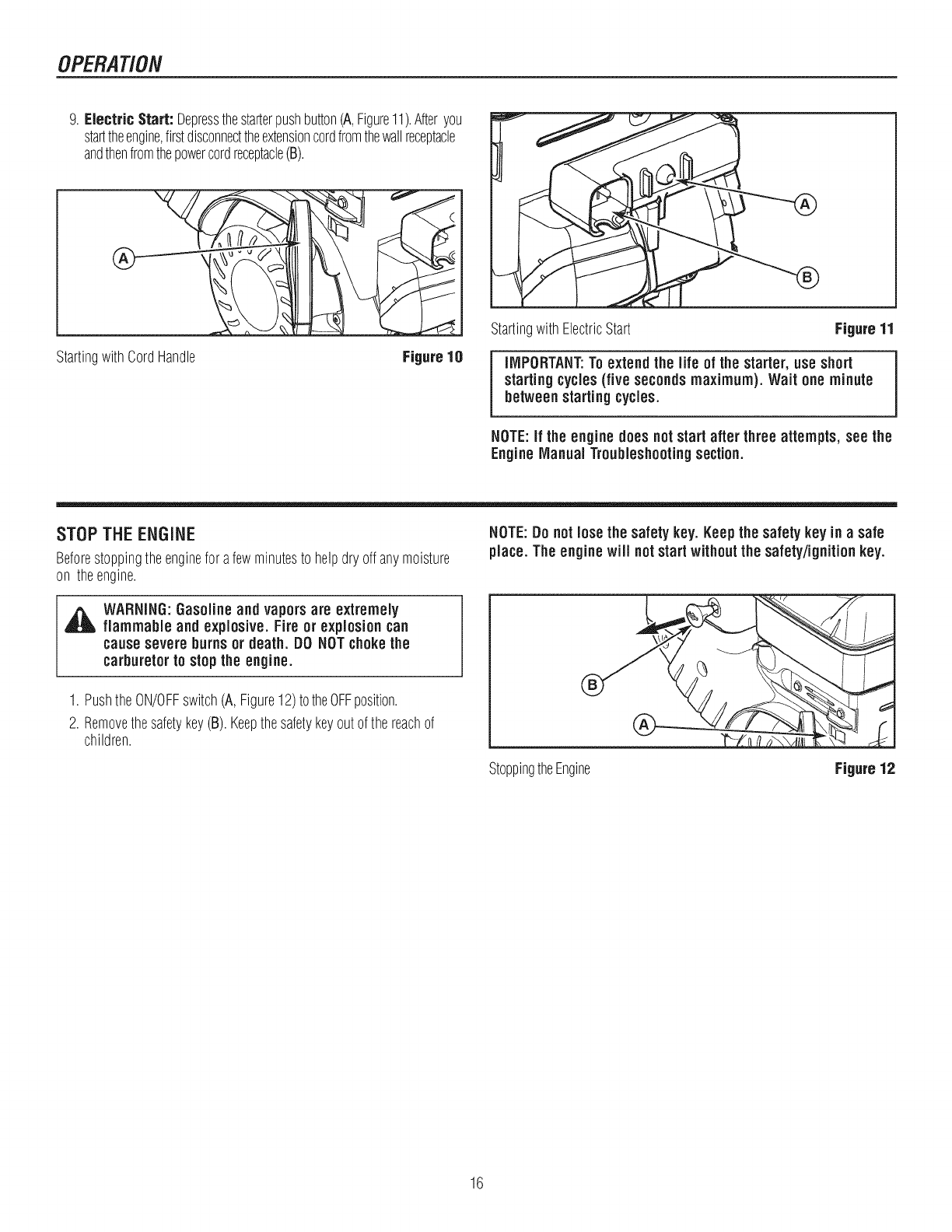
START THE ENGINE
BesurethatengineoilisatFULLmarkontheoilfill cap/dipstick.Thesnow
throwerengineisequippedwithanA.C.electricstarterandrecoilstarter.Before
startingtheengine,becertainthatyouhavereadthefollowinginformation.
Ifenginefloods,setthechoketotheOPEN/RUNpositionandcrankuntiltheen-
ginestarts.
,A_WARNING: Theelectricstarteris equippedwitha
three-wire powercordand plugdesignedto operateonAC
householdcurrent.Thepowercordmust beproperly
groundedat all times to avoidthe possibilityof electricshock
whichcancauseinjurytothe operator.Followall instructions
carefullyas setforth:
Makesureyourhousehasa three=wiregroundedsystem.
Ifyouarenotsure,aska licensedelectrician.If yourhousedoes
nothavea three-wire groundedsystem,do notusethis electric
starterunderanycondition.
Ifyourhousehas athree-wire groundedsystembut a three-hole
receptacleis not availableto connectthe electricstarter,havea
three-hole receptacleinstalledbya licensedelectrician.
,_ WARNING:Toconnectpower cord, always connectthe
power cordfirst to the switch box located on the
engine and then plugthe other end into a three-hole
grounded receptacle.
,_ WARNING:Todisconnectthe power cord, always
unplugthe end connectedto the three-hole grounded
receptacle first.
Start the engineas follows:
1. Checktheoillevel.Seethe"Check/AddOil"sectionintheENGINE
MANUAL.
2. Makesureequipmentdrivecontrolsaredisengaged.
3. PushtheON/OFFswitch(A,Figure8)totheONposition.
StartingtheEngine Figure8
4. Insertthesafetykey(A, Figure9) intothesafetykeyslotandpush
fullyin to theRUNposition.
5. Turnthechokeknob(B)fully clockwiseif engineis cold.
NOTE:Donot use the choke to start a warm engine.
6. Pushtheprimerbutton(C)twotimes.
NOTE:Donot use the primerto start a warm engine.
NOTE:Ensurethat electric extension cordis removedfrom the
power receptacle.
InsertingSafetyKey Figure9
7. BewindStart: Firmlyholdthestartercordhandle(A,Figure10).Pull
thestartercordhandleslowlyuntilresistanceisfelt,thenpullrapidly.
,ll_ WARNING:Rapid retractionof the starter cord (kickback)
will pull your hand and arm toward the engine faster
than youcan let go. Brokenbones,fractures, bruises,
or sprainscouldresult. When starting engine, pull the
starter cordslowly until resistance is felt and then pull
rapidlyto avoid kickback.
NOTE:If the engine does notstart after three attempts, see the
Engine Manual Troubleshootingsection.
8. Electric Start: Firstconnecttheextensioncordtothepowercord
receptacleandthenintoawallreceptacle.Ifadditionalextensioncordis
required,makesureit is three-wire.
_l_ WARNING:if the extension cord is damaged, it must
be replaced bythe manufacturer(or its service agent)
or asimilarly qualified personto avoid a hazard.
15
OPERATION
9. Electric Start: Depressthestarterpushbutton(A,Figure11).Afteryou
starttheengine,firstdisconnecttheextensioncordfromthewallreceptacle
andthenfromthepowercordreceptacle(B).
®
StartingwithCordHandle Figure 10
StartingwithElectricStart Figure 11
IMPORTANT:Toextend the life of the starter, use short
startingcycles(five secondsmaximum). Wait one minute
between startingcycles.
NOTE:If the engine does notstart after three attempts, see the
Engine Manual Troubleshootingsection.
STOPTHEENGINE
Beforestoppingtheenginefor afewminutesto helpdry offanymoisture
on theengine.
NOTE:Donot lose the safety key. Keepthe safety key in asafe
place. The enginewill notstart withoutthe safety/ignitionkey.
_ARNING:Gasolineand vaporsare extremely
flammable and explosive. Fire or explosion can
cause severe burnsor death. DO NOTchokethe
carburetorto stopthe engine.
1. PushtheON/OFFswitch(A,Figure12)totheOFFposition.
2. Removethesafetykey(B).Keepthesafetykeyoutof the reachof
children.
StoppingtheEngine Figure 12
16
OPERATION
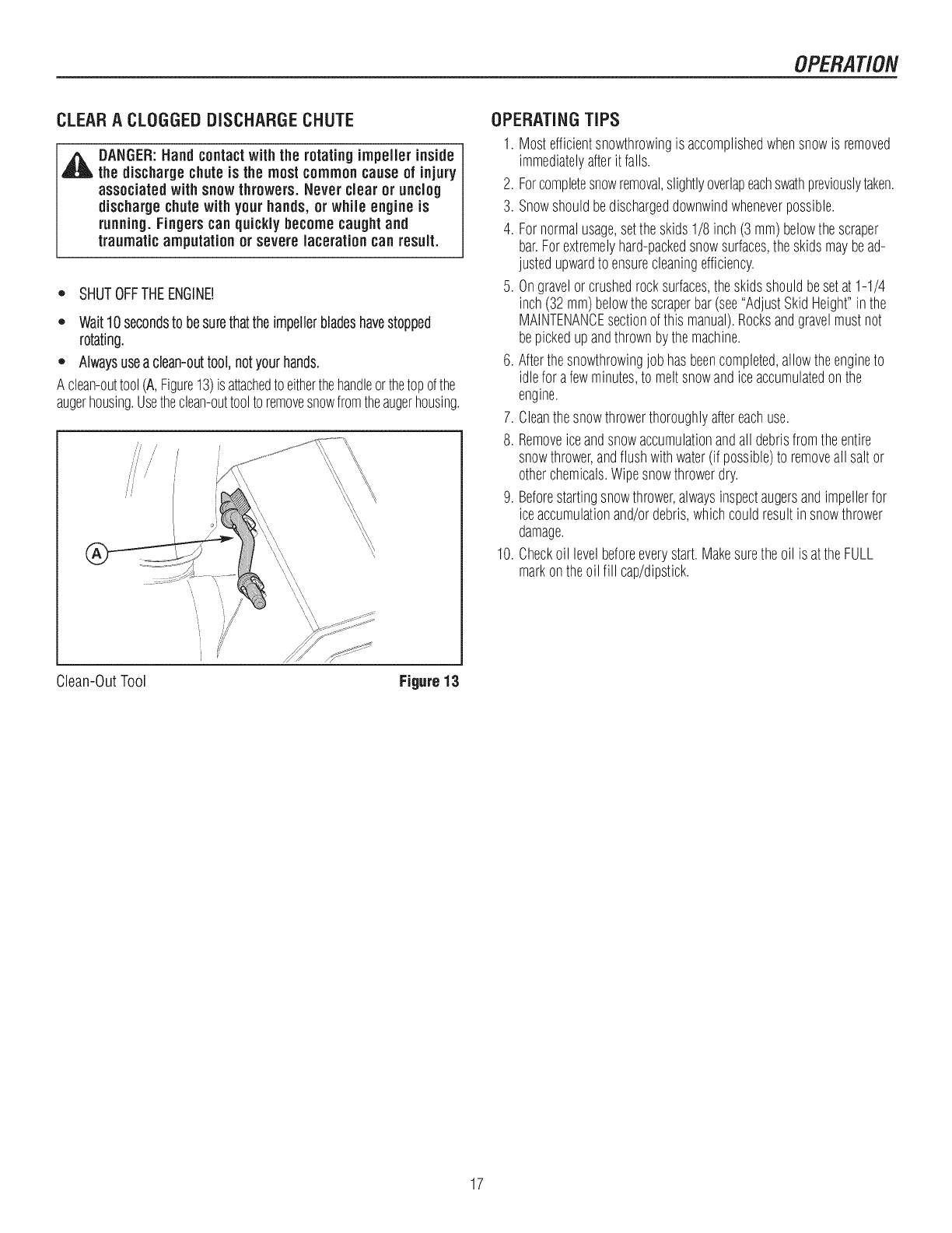
CLEARA CLOGGEDDISCHARGECHUTE
_k ANGER:Hand contactwith the rotating impeJlerinside
the dischargechuteis the most commoncause of injury
associated with snowthrowers. Never dear or unclog
dischargechute with your hands, or while engine is
running.Fingerscan quickly becomecaught and
traumatic amputation or severe lacerationcan result.
_' SHUTOFFTHEENGINE!
,, Wait10secondsto besurethattheimpellerbladeshavestopped
rotating.
,' Alwaysusea clean-outtool,notyourhands.
A clean-outtool(A,Figure13)isattachedtoeitherthehandleorthetopofthe
augerhousing.Usetheclean-outtoolto removesnowfromtheaugerhousing.
\\\,\
\i
\\ \
Clean-OutTool Figure 13
OPERATINGTiPS
1. Mostefficientsnowthrowingis accomplishedwhensnowis removed
immediatelyafterit falls.
2. Forcompletesnowremoval,slightlyoverlapeachswathpreviouslytaken.
3. Snowshouldbedischargeddownwindwheneverpossible.
4. Fornormalusage,setthe skids1/8 inch(3 mm)belowthe scraper
bar.Forextremelyhard-packedsnowsurfaces,the skidsmaybead-
justedupwardto ensurecleaningefficiency.
5. Ongravelorcrushedrocksurfaces,theskidsshouldbesetat 1-1/4
inch(32mm)belowthescraperbar(see"AdjustSkidHeight"inthe
MAINTENANCEsectionof this manual).Rocksandgravelmustnot
bepickedupandthrownbythemachine.
6. Afterthesnowthrowingjobhasbeencompleted,allowtheengineto
idlefor afewminutes,to meltsnowandiceaccumulatedonthe
engine.
7. Cleanthesnowthrowerthoroughlyaftereachuse.
8. Removeiceandsnowaccumulationandall debrisfromtheentire
snowthrower,andflushwithwater(if possible)toremoveall saltor
otherchemicals.Wipesnowthrowerdry.
9. Beforestartingsnowthrower,alwaysinspectaugersandimpellerfor
iceaccumulationand/ordebris,whichcouldresultin snowthrower
damage.
10. Checkoil levelbeforeeverystart.Makesurethe oil is attheFULL
markontheoil fill cap/dipstick.
17
MAINTENANCE
SERVICERECOMMENDATIONS
FIRST BEFORE AFTER EVERY EVERY EVERY BEGINNING BEFORE
PROCEDURE 2 EACH EACH 5 10 25 EACH STORAGE
HOURS USE USE HOURS HOURS HOURS SEASON
Checkto MakeSure
AugerBladeStopsWithin
5 SecondsAfterRight ,/
SAFETY ControlLeveris Released
LubricateControlLevers ,/ ,/ ,/
andLinkages
CheckSnowThrowerfor
LooseHardware "/ '/
LubricateHexShaftand
Chains '/ '/
LubricateAugerShaft
Fittings ,/ ,/
SNOWTHROWER LubricateChuteRotation
GearandDeflector ,/
Mechanism
RemoveAll Snowand
SlushoffSnowThrowerto
PreventFreezingof Auger
or Controls
v"
CheckTirePressure ,/
L_______ i i ,,,,, i
Oil,Check ¢ ¢ ¢
OiI,Change ,/ ,/ ,/
ENGINE CheckandReplace
SparkPlug '/
NOTE:The warrantyon this snowthrowerdoes not coveritems
that have beensubjectedto operator abuse or negligence.To
receivefull value from the warranty, operator mustmaintain
snowthrower as instructedinthis manual.
TheaboveService Recommendations aresuppliedto assisttheopera-
torto properlymaintainthesnowthrower.
18
MAINTENANCE
LUBRICATEAUGERGEARBOX
Theaugergearboxis lubricatedatthefactoryandshouldnotrequire
additionallubrication,If for somereasonthelubricantshouldleakout,
or if theaugergearboxhasbeenserviced,addLubriplateGR132Greaseor
equivalent.Maximum3-1/4 ounces,(92grams)shouldbeused.
Removefiller plug(A,Figure14),onceayear.Ifgreaseis visible,donot
add.Ifgreaseis notvisible,usea pieceoffinewire,likeadipstickto check
if thereis greaseinthegearbox.MobiluxEP1andShellAlvaniaEP1are
suitableequivalents.
,,¢
LubricatingControlLeverLinkage Figure 15
LUBRICATEDISCHARGECHUTEAND DEFLECTOR
Lubricatethechuterotationgear(A,Figure16)anddeflectorhinge(B)with
automotivetypeoileverytwenty-five(25)operatinghours.
LubricatingAugerGearBox Figure 14
LUBRICATEAUGERSHAFTFITTINGS
1. Usingahandgreasegun,lubricatetheaugershaftfittings(B,Figure
14)everyten(10)operatinghours.Eachtimea shearpinis replaced,
theaugershaft(C) MUSTbegreased.(See"AugerShearPinReplace-
ment"section.)
2. Forstorageorwhenreplacingshearpins,removeshearpinsand
lubricateaugershaftfittings(B).Rotateaugersseveraltimesonthe
shaftandreinstalltheshearpins.
LUBRICATE CONTROL LEVER LINKAGE
Checkthefunctionof theFree-Handcontrols.Thecontrolsshouldfunction
asdescribedin theOPERATIONsection.
,_ WARNING:It is critical for the safe operation of the
unit that the controlsdisengagewhen released.
Lubricatethe linkagefor thetraction/Free-Handcontrol(A, Figure15),
speedselectcontrol(B),andaugercontrol(C)everyten(10)operating
hours,or asnecessaryto ensuresafeoperation.
NOTICE:Underno circumstancesshould the unit be usedif the
controlsdo notfunction properly.
LubricatingDischargeChuteandDeflector Figure 16
19
MAINTENANCE
ENGINEMAINTENANCE
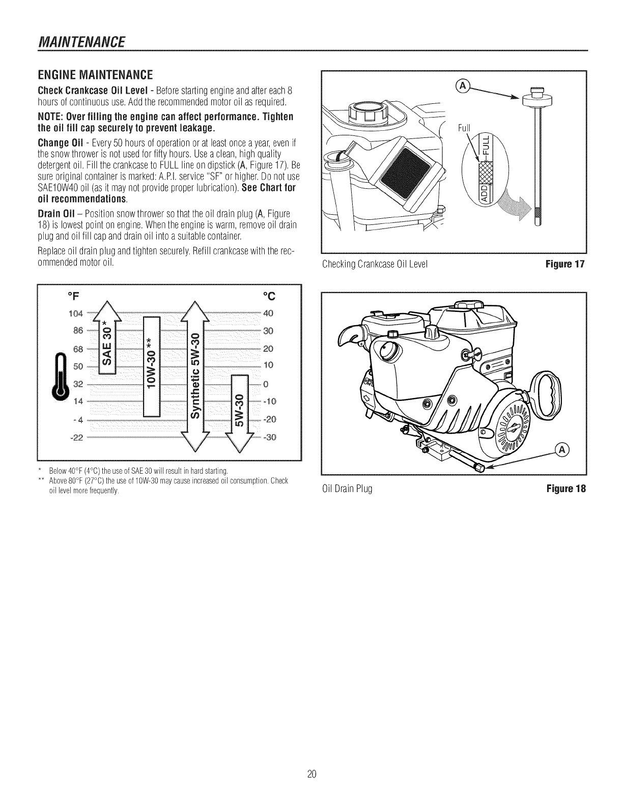
Check Crankcase Oil Level - Beforestartingengineandaftereach8
hoursof continuoususe.Addtherecommendedmotoroil as required.
NOTE:Over filling the engine can affect performance.Tighten
the oil fill cap securely to prevent leakage.
Change Oil - Every50 hoursof operationorat leastonceayear,evenif
thesnowthroweris notusedfor fiftyhours.Useaclean,highquality
detergentoil. Fill thecrankcaseto FULLlineon dipstick(A, Figure17).Be
sureoriginalcontaineris marked:A.P.I.service"SF"orhigher.Do notuse
SAE10W40oil (asit maynotprovideproperlubrication).See Chart for
oil recommendations.
Drain Oil - Positionsnowthrowersothattheoil drainplug(A, Figure
18)is lowestpointonengine.Whentheengineis warm,removeoil drain
plugandoil fill capanddrainoil intoasuitablecontainer.
Replaceoil drainplugandtightensecurely.Refillcrankcasewiththe rec-
ommendedmotoroil.
Full
CheckingCrankcaseOil Level Figure 17
-22
°C
Below40°F (4°C)the useof SAE30will result in hardstarting.
** Above80°F (27°C)the useof 10W-30maycauseincreasedoil consumption=Check
oil levelmorefrequently. Oil DrainPlug Figure 18
2O
MAINTENANCE
CHANGETHESPARKPLUG
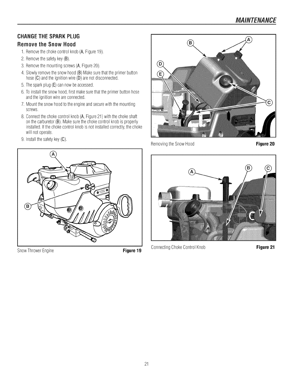
Remove the Snow Hood
1. Removethechokecontrolknob(A,Figure19).
2. Removethesafetykey(B).
3. Removethemountingscrews(A, Figure20).
4. Slowlyremovethesnowhood(B)Makesurethattheprimerbutton
hose(C)andtheignitionwire(D)arenotdisconnected.
5. Thesparkplug(E)cannowbeaccessed.
6. Toinstallthesnowhood,first makesurethattheprimerbuttonhose
andtheignitionwireareconnected.
7. Mountthesnowhoodto theengineandsecurewiththemounting
screws.
8. Connectthechokecontrolknob(A,Figure21)withthechokeshaft
onthecarburetor(B).Makesurethechokecontrolknobis properly
installed.Ifthechokecontrolknobis notinstalledcorrectly,thechoke
will notoperate.
9. Installthesafetykey(C). RemovingtheSnowHood Figure 20
SnowThrowerEngine Figure 19 ConnectingChokeControlKnob Figure 21
21
MAINTENANCE
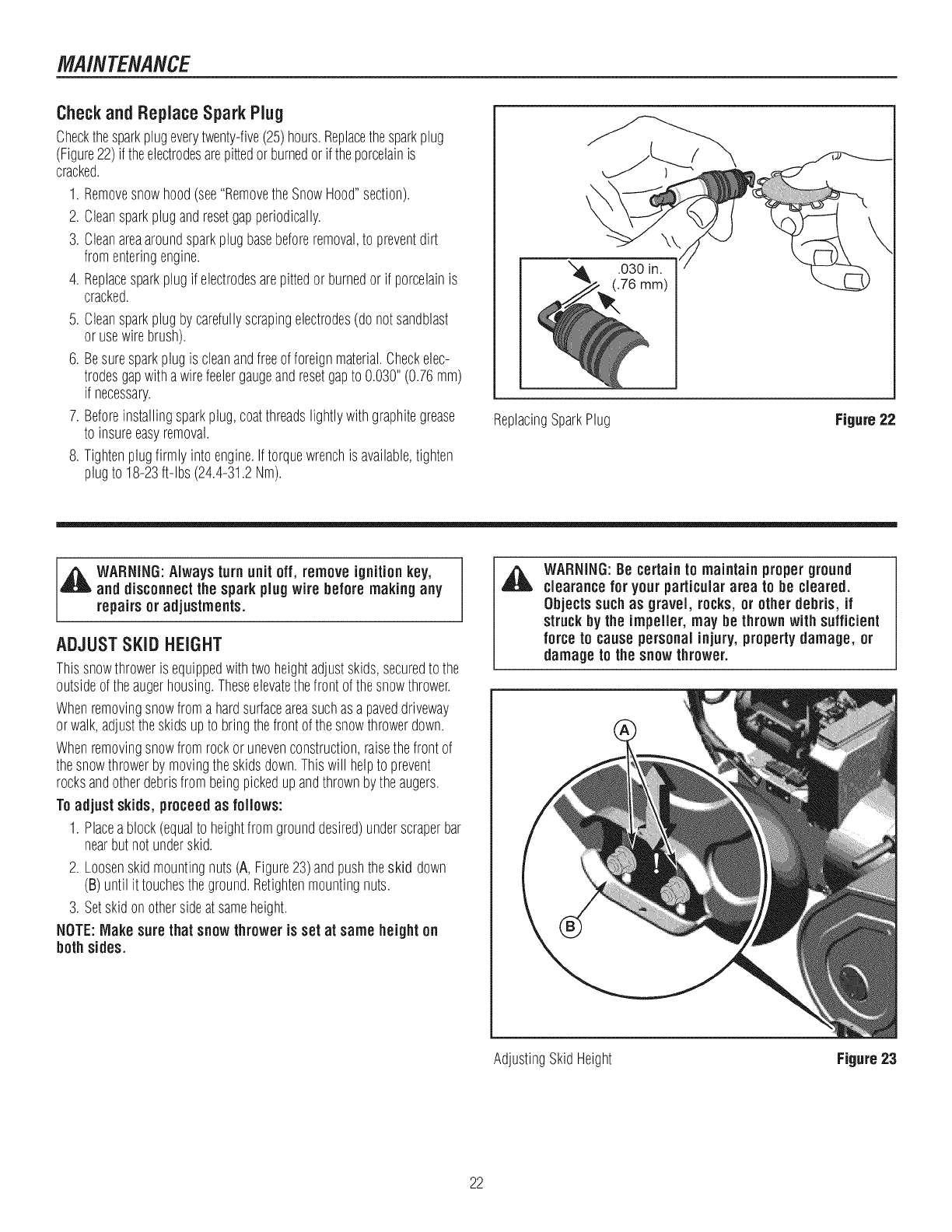
CheckandReplaceSpark Plug
Checkthesparkplugeverytwenty-five(25)hours.Replacethesparkplug
(Figure22)if theelectrodesarepittedorburnedorif theporcelainis
cracked.
1. Removesnowhood(see"RemovetheSnowHood"section).
2. Cleansparkplugandresetgapperiodically.
3. Cleanareaaroundsparkplugbasebeforeremoval,to preventdirt
fromenteringengine.
4. Replacesparkplugif electrodesarepittedor burnedor if porcelainis
cracked.
5. Cleansparkplugby carefullyscrapingelectrodes(donotsandblast
orusewirebrush).
6. Besuresparkplugis cleanandfreeof foreignmaterial.Checkelec-
trodesgapwithawirefeelergaugeandresetgapto 0.030"(0.76ram)
if necessary.
7. Beforeinstallingsparkplug,coatthreadslightlywithgraphitegrease
to insureeasyremoval.
8. Tightenplugfirmlyinto engine.Iftorquewrenchis available,tighten
plugto 18-23ft-lbs (24.4-31.2Nm).
\
ReplacingSparkPlug Figure 22
,_ WARNING:Alwaysturn unit off, remove ignitionkey,
and disconnectthe sparkplugwire before making any
repairs or adjustments.
ADJUSTSKiD HEIGHT
Thissnowthroweris equippedwithtwoheightadjustskids,securedto the
outsideoftheaugerhousing.Theseelevatethefrontofthesnowthrower.
Whenremovingsnowfromahardsurfaceareasuchasa paveddriveway
orwalk,adjusttheskidsupto bringthefrontofthesnowthrowerdown.
Whenremovingsnowfromrockor unevenconstruction,raisethefrontof
thesnowthrowerbymovingtheskidsdown.Thiswill helpto prevent
rocksandotherdebrisfrombeingpickedupandthrownbytheaugers.
Toadjustskids, proceedas follows:
1. Placeablock(equalto heightfromgrounddesired)underscraperbar
nearbutnotunderskid.
2. Loosenskidmountingnuts(A, Figure23)andpushtheskid down
(B)until it touchestheground.Retightenmountingnuts.
3. Setskidonothersideatsameheight.
NOTE:Make surethat snowthroweris set at same heighton
both sides.
WARNING:Be certain to maintainproper ground
clearance for your particulararea to be cleared.
Objects suchas gravel, rocks, or other debris, if
struckby the impeller, may be thrown with sufficient
force to cause personalinjury, propertydamage, or
damageto the snowthrower.
AdjustingSkidHeight Figure 23
22
MAINTENANCE
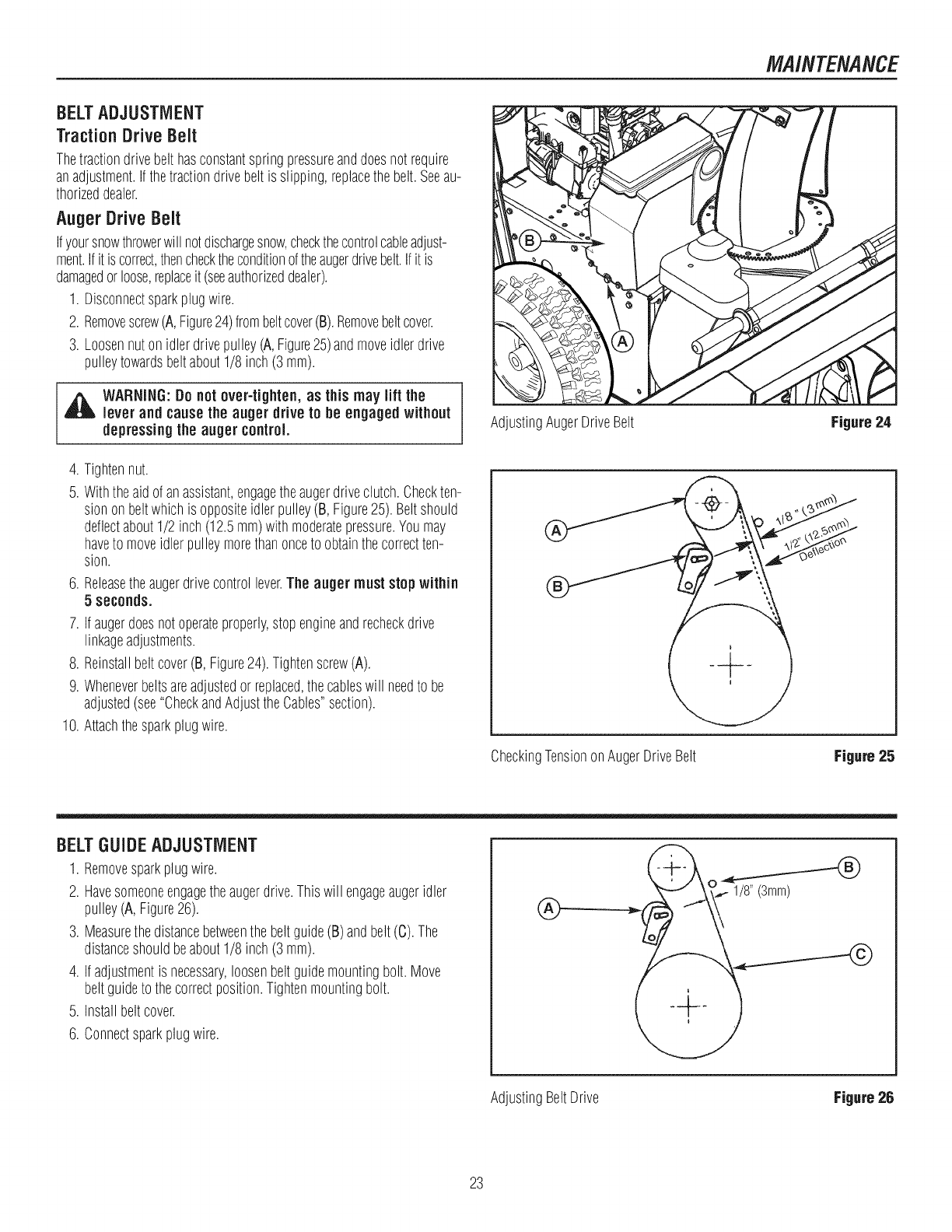
BELTADJUSTMENT
TractionDriveBelt
Thetractiondrivebelthasconstantspringpressureanddoesnotrequire
anadjustment.Ifthetractiondrivebelt is slipping,replacethebelt.Seeau-
thorizeddealer.
AugerDriveBelt
Ifyoursnowthrowerwill notdischargesnow,checkthecontrolcableadjust-
ment.Ifit iscorrect,thenchecktheconditionoftheaugerdrivebelt.Ifit is
damagedor loose,replaceit (seeauthorizeddealer).
1. Disconnectsparkplugwire.
2. Removescrew(A,Figure24)frombeltcover(B).Removebeltcover.
3. Loosennutonidlerdrivepulley(A,Figure25)andmoveidlerdrive
pulleytowardsbeltabout1/8inch(3 mm).
_ARNING:Donot over-tighten, as this may lift the
lever and causethe auger drive to be engagedwithout
depressingthe auger control.
4. Tightennut.
5. Withtheaidof anassistant,engagetheaugerdriveclutch.Checkten-
sionon beltwhichis oppositeidlerpulley(B,Figure25).Beltshould
deflectabout1/2 inch(12.5mm)withmoderatepressure.Youmay
haveto moveidlerpulleymorethanonceto obtainthecorrectten-
sion.
6. Releasetheaugerdrivecontrollever.The auger muststopwithin
5 seconds.
7. Ifaugerdoesnotoperateproperly,stopengineandrecheckdrive
linkageadjustments.
8. Reinstallbeltcover(B, Figure24).Tightenscrew(A).
9. Wheneverbeltsareadjustedor replaced,thecableswill needto be
adjusted(see"CheckandAdjusttheCables"section).
10. Attachthesparkplugwire.
AdjustingAugerDriveBelt Figure24
CheckingTensiononAugerDriveBelt Figure25
BELT GUIDE ADJUSTMENT
1. Removesparkplugwire.
2. Havesomeoneengagetheaugerdrive.Thiswill engageaugeridler
pulley(A, Figure26).
3. Measurethedistancebetweenthe beltguide(B)andbelt(C).The
distanceshouldbeabout1/8inch(3 ram).
4. Ifadjustmentis necessary,loosenbeltguidemountingbolt.Move
beltguideto thecorrectposition.Tightenmountingbolt.
5. Installbeltcover.
6. Connectsparkplugwire.
®1/8"(3mm)
AdjustingBeltDrive Figure 26
23
MAINTENANCE
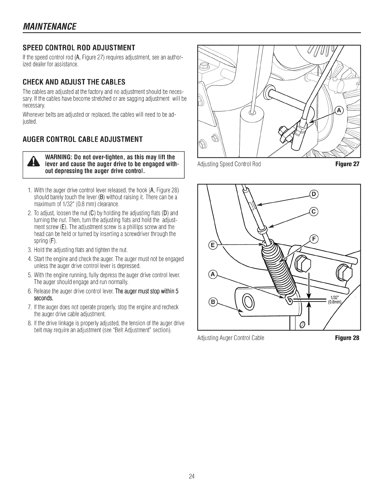
SPEEDCONTROLRODADJUSTMENT
Ifthespeedcontrolrod(A,Figure27)requiresadjustment,seeanauthor-
izeddealerfor assistance.
CHECKANDADJUSTTHECABLES
Thecablesareadjustedatthefactoryandnoadjustmentshouldbeneces-
sary.Ifthecableshavebecomestretchedoraresaggingadjustmentwill be
necessary.
Wheneverbeltsareadjustedor replaced,thecableswill needto bead-
justed.
AUGER CONTROL CABLE ADJUSTMENT
,_ WARNING:Do not over-tighten,as this may lift the
lever and causethe auger drive to be engaged with-
out depressingtheauger drive control.
1. Withtheaugerdrivecontrolleverreleased,thehook(A, Figure28)
shouldbarelytouchthelever(B)withoutraisingit.Therecanbea
maximumof 1/32"(0.8mm)clearance.
2. Toadjust,loosenthenut (C)by holdingtheadjustingflats(D)and
turningthenut.Then,turntheadjustingflatsandholdthe adjust-
mentscrew(E).Theadjustmentscrewis a phillipsscrewandthe
headcanbeheldorturnedby insertingascrewdriverthroughthe
spring(F).
3. Holdtheadjustingflatsandtightenthenut.
4. Starttheengineandchecktheauger.Theaugermustnotbeengaged
unlesstheaugerdrivecontrolleveris depressed.
5. Withtheenginerunning,fully depresstheaugerdrivecontrollever.
Theaugershouldengageandrunnormally.
6. Releasetheaugerdrivecontrollever.Theaugermuststopwithin5
seconds.
7. Iftheaugerdoesnotoperateproperly,stoptheengineandrecheck
theaugerdrivecableadjustment.
8. Ifthedrivelinkageis properlyadjusted,thetensionof theaugerdrive
beltmayrequireanadjustment(see"BeltAdjustment"section).
AdjustingSpeedControlRod
AdjustingAugerControlCable
Figure 27
Figure28
24
MAINTENANCE
TRACTIONCONTROLCABLEADJUSTMENT
1. Removethegasfromthegastank.Standthesnowthrowerupon the
frontendof theaugerhousing.
[_ ARNING:Drainthe gasoline outdoors, away from fire
or flame.
2. Loosenthebolts(A,Figure29)on eachsideof thebottompanel(B).
3. Removethebottompanel.
4. Slidethecableboot(A, Figure30)offthecableadjustmentbracket
(B) I
5. Pushthebottomofthetractiondrivecable(C)throughthecable
adjustmentbracketuntilthe "Z"hook(D)canberemoved.
6. Removethe"Z"hookfromthecableadjustmentbracket.Movethe"Z"
hookdownto thenextadjustmenthole.
7. Pullthetractiondrivecableupthroughthecableadjustmentbracket.
81Putthecablebootoverthecableadjustmentbracketi
9. Tochecktheadjustment,depressthedriveleverandcheckthelength
of thedrivespring(A,Figure31). Incorrectadjustment,thelength
of thedrivespringis aminimum3 inches(76mm)anda maximum
3-3/8 inches(85mm).
10. Installthebottompanel(B,Figure29)1
11. Tightenthebolts(A)oneachsideof thebottompanel.
TractionDriveCable Figure 30
CheckingAdjustmentofTractionDriveCable Figure 31
AdjustingTractionDriveCable Figure 29
25
MAINTENANCE
CHUTEROTATIONMOTORADJUSTMENT
Iftheelectricchuterotatordoesnotfunctionproperly,checktheelectrical
connectionsandthenperformtheprocedurebelow.
1. Removetherotatormotorcover.
2. Lubricatethechuteringgear.
3. Loosenthescrews(A, Figure32)securingtherotatormotorandad-
justso thatthemotorgearandchuteringgearmesh.Tightenthe
capscrews.
4. Reinstallthechuterotationcover.
AdjustingChuteRotationMotor Figure 32
AUGERSHEARPiN REPLACEMENT
Theaugersaresecuredtotheaugershaftwithspecialshearpinsthatare
designedto breakif anobjectbecomeslodgedin theaugerhousing.Use
of a hardergradeshearpinwill reducetheprotectionprovidedbythe
shearpin.
,_WARNING: Donot go nearthe dischargechuteor auger
when the engine is running.Do notrun the engine if
any coveror guard is removed.
Undermostcircumstances,if theaugerstrikesanobjectwhichcould
causedamageto theunit,theshearpinwill break.Thisprotectsthegear
boxandotherpartsfromdamage.
Theshearpins(AandB, Figure33)arelocatedontheaugershaft.Replace
abrokenshearpinasfollows.
1. Tapoutthebrokenshearpinwitha pinpunch.
2. Installa newshearpinandcotterpin.Bendtheendsofthecotterpin
down.
iMPORTANT:Do not replaceshearpins withanything other
thanthe correctgradereplacement shearpin. Useof bolts,
screws,or hardergrade shearpins can result in equipment
damage.
ReplacingBrokenShearPin Figure 33
26
MAINTENANCE
CHECKTHETIRES
Checktiresfor damage.Checktheair pressureinthetireswith an
accurategauge(seeFigure34).
_ AUTION:Avoidinjury! ExpJosiveseparationof tire
and rim parts is possible when they are serviced
incorrectly.
= Donotattempt to mountatire without the proper
equipment and experience to perform the job.
= Donot inflate the tires above the recommendedpressure.
= Donotweld or heat a wheel and tire assembly. Heat can
cause an increase in air pressure resultingin an
explosion. Welding can structurallyweaken or deform the
wheel.
• Do not standin front or over the tire assembly when
inflating. Use appropriate tool that allows youto standto
one side.
NOTICE:Check side of tire for maximum tire pressure. DO
NOTexceed maximum.
CheckingTire Air Pressure Figure 34
27
STORAGE
OFFSEASONSTORAGE
,A WARNING:Never storethe engine, withfuel in the tank,
indoorsor in apoorventilated enclosurewhere fuel
fumes couldreachan openflame, sparkor pilot light
as on a furnace,water heater, clothes dryer,etc.
Handle gasoline carefully. It is highlyflammable and
carelessuse could result in seriousfire damage to your
personand/or property.
Drain fuel into approvedcontainersoutdoors, away from
open flame.
If thesnowthrowerwill bestoredforthirty (30)daysor moreatthe endof
thesnowseason,thefollowingstepsarerecommendedto prepareyour
snowthrowerfor storage.
NOTE:Gasoline must be removedor treated to prevent gum
depositsfrom forming inthe tank, filter, hose, and carburetor
duringstorage.
1. Removegasoline,by runningengineuntil tankis emptyandengine
stops.Ifyoudonotwantto removethegasoline,addfuelstabilizer
to anygasolineleftinthetankto minimizegumdepositsandacids.
Ifthetankis almostempty,mixstabilizerwithfreshgasolinein a
separatecontainerandaddsomeofthemixtureto thetank.ALWAYS
FOLLOWINSTRUCTIONSONSTABILIZERCONTAINER.THENRUN
ENGINEATLEAST10MINUTESAFTERSTABILIZERISADDEDTO
ALLOWMIXTURETOREACHCARBURETOR.STORESNOW
THROWERINSAFEPLACE.
2. Youcanhelpkeepyourengine(4-cyclesonly)in goodoperating
conditionby changingoil beforestorage.
3. Lubricatethe piston/cylinderarea.Thiscanbedonebyfirst removing
thesparkplugandsquirtingcleanengineoil intothe sparkplughole.
Thencoverthesparkplugholewitharagto absorboil spray.Next,
rotatetheengineby pullingthestartertwoorthreetimes.Finally,
reinstallsparkplugandattachsparkplugwire.
4. Thoroughlycleanthe snowthrower.
5. Lubricateall lubricationpoints(see"Lubrication"topicsinthe
MAINTENANCEsection).
6. Makesureall nuts,bolts,andscrewsaresecurelyfastened.Inspect
allvisiblemovingpartsfor damage,breakage,andwear.Replaceif
necessary.
7. Touchupall rustedorchippedpaintsurfaces;sandlightlybefore
painting.
8. Coverthebaremetalpartsof thesnowthrowerhousingauger,and
theimpellerwithrustpreventative.
9. If possible,storeyoursnowthrowerindoorsandcoverit to give
protectionfromdustanddirt.
10. Onmodelswithfolding handles,loosentheknobsthatsecurethe
upperhandle.Rotatetheupperhandleback.
11. Ifthemachinemustbestoredoutdoors,blockupthesnowthrower
andensuretheentiremachineis offtheground.Coverthesnow
throwerwithaheavytarpaulin.
LUBRICATEHEXSHAFTANDCHAINS
,& CAUTION:Do not allow grease or oil to contactthe
rubberfrictionwheel or the discdrive plate, if the
discdrive plate or friction wheel come in contactwith
greaseor oil damageto rubberfriction wheel will
result.
NOTICE:If greaseor oil comesinto contactwith the discdrive
plate or frictionwheel, makesureto clean plate and wheel
thoroughlywith an alcohol basesolvent.
1. Positionspeedselectlever(E,Figure4) infirst forwardgear.
2. Drainfuelto anapprovedcontainer.
3. Standthesnowthrowerupontheaugerhousingend.
NOTE:When the crankcaseis filled with oil, do not leave
the snowthrowerstandingup on the auger housingfor an
extended period of time.
4. Removethebottompanel.
5. Lubricatethechains(A, Figure35)witha chaintypelubricant.
6. Wipethehexshaft(B)andsprockets(C)with5W30motoroil, before
storageandatthebeginningof eachseason.
7. Installthebottompanel.
LubricatingHexShaftandChains Figure35
REMOVEFROMSTORAGE
1. Puttheupperhandleintheoperatingposition,tightentheknobsthat
securetheupperhandle.
2. Fill thefueltankwithafreshfuel.
3. Checkthesparkplug.Makesurethegapis correct.Ifthesparkplug
is wornordamaged,replacebeforeusing.
4. Makesureall fastenersaretight.
5. Makesureall guards,shields,andcoversarein place.
6. Makesureall adjustmentsarecorrect.
28
TROUBLESHOOTING
PROBLEM LOOKFOR REMEDY
Free-HandTM controlisACTIVE. ReleasebothaugercontrolandFree-HandTM controlto stopauger.
lAuger does not stopwithin
5 secondsafter right
controllever is released. Augerdrivebeltout of Adjustaugerbelt.
adjustment.
Augerbeltguideoutof Adjustaugerbeltguide.
adjustment.
Discharge chuteor Electricalfailure. Seeauthorizeddealer.
deflectordoes notwork
(electric).
Discharge chute or Dischargechuteor deflectorout Adjustand/orlubricatecontrollinkage.
i deflectordoes notwork ofadjustmentor needs
i(remote-manual). lubrication.
Drive fails to move snow Tractioncontrolout of Readjustdrive,orselectspeedleversettingonespeedfaster.
throwerat slowspeeds, adjustment.
Keyis off. Pushkeyinto theONposition.
Failureto primea coldengine. Pressprimerbuttontwiceandrestart.
Fuelshut-offvalveis in CLOSEDTurnvalveto OPENposition.
Enginefails to start, position.
Outof fuel. Fill fueltank.
ChokeOFF- coldengine. TurnchokeON,setthrottleto FAST.
Engineflooded. Turnchoketo OFF;try starting.
Nospark. Checkgap.Gapsparkplug,cleanelectrode,or replaceplugas necesary.
Waterin fuel,oroldfuel. Draintank.(Disposeof fuel atanauthorizedhazardouswastefacility.)Fillwith
freshfuel.
Enginestarts hard or runs Fuelmixturetoo rich. Movechoketo OFFposition.
poorly.
Sparkplugfaulty,fouled,or Cleanandgapsparkplug,or replace.
gappedimproperly.
Fuelcapventis blocked. Clearvent.
Excessivevibration. Loosepartsordamaged Stopengineimmediately.Tightenall hardware.Ifvibrationcontinues,havethe unit
impeller, servicedby anauthorizeddealer.
Snow throwerdoes not Tractioncontrolout of Adjusttractioncontrollinkage.
stopwhen tractioncontrol adjustment.
lever is released.
Tirepressurenotequal. Checktire pressure.
Snow throwerveers to Onewheelis setinfree- Makesurethelefttractionlockpinis in theINNERholes(to engagethetraction
one side. wheelingmode.(Tractionlock drive).
pinis in theOUTERhole.)
29
TROLIBLESHOOT/NG
PROBLEM LOOKFOR REMEDY
Scraper bar doesnot clean Skidshoesimproperlyadjusted. Raiseor lowerskidshoes.
hard surface.
Drivebelt looseor damaged. Replacedrivebelt.Seeauthorizeddealer.
Unit fails to propel itself. Incorrectadjustmentof traction Adjusttractiondrivecable.Referto "CableAdjustment"inthe MAINTENANCE
drivecable, sectionof thismanual.
Wornordamagedfrictiondisc. Replacefrictiondisc.Seeauthorizeddealer.
Augerdrivebelt looseor Replaceoradjustaugerdrivebelt.Referto "DriveBeltAdjustment"in the
damaged. MAINTENANCEsectionof this manual,or seeauthorizeddealer.
Unit fails to discharge Augercontrolcablenotadjusted Adjustaugercontrolcable.Referto "CableAdjustment"in theMAINTENANCE
snow. correctly, sectionof thismanual.
Brokenshearpin. Replaceshearpin.Referto "AugerShearPinReplacement"inthe MAINTENANCE
sectionof thismanual.
Dischargechuteclogged. Stopengineimmediately.Alwaysusetheclean-outtoolto cleara clogged
dischargechute,notyour hands.Cleandischargechuteandinsideof auger
housing.Referto WARNINGSin OPERATORSAFETYsection.
Foreignobjectlodgedinauger. Stopengineimmediately.Alwaysusetheclean-outtoolto cleara cloggedchute,
notyourhands.Removeobjectfromauger.Referto WARNINGSin OPERATOR
SAFETYsection.
30
Briggs & Stratton Power Products Group, LLC will repair and/or replace, free dcharge, any part(s) of the equipment that is
defective in material or workmanship or both. Briggs & Stratton Corporation will repair and/or replace, free of charge, any
part(s) dthe Briggs and Stratton engine* (if equipped) that is defective in material or workmanship or both. Transportation
charges on product submitted for repair or replacement under this warranty must be borne by purchaser. This warranty is
effective for the time periods and subject to the conditions stated below. For warranty service, find the nearest Authorized
Service Dealer using our dealer locator at www.BriggsandStratton.com.
There is no other express warranty. Implied warranties, including those of merchantability and fitness for a particular
purpose, are limited to one year from purchase or to the extent permitted by taw. Liability for incidental or consequential
damages are excluded to the extent exclusion is permitted by taw.
Some states or countries do not allow limitations on how long an implied warranty lasts, and some states or countries do
not allow the exclusion or limitation of incidental or consequential damages, so the above limitation and exclusion may not
apply to you. This warranty gives you specific legal rights and you may also have other rights which vary from state to state
or country to country.
The warranty period begins on the date of purchase by the first retail consumer or commercial end user, and continues for the
period of time stated above. "Consumer use" means personal residential household use by a retail consumer. "Commercial
use" means all other uses, including use for commercial, income producing or rental purposes. Once product has experienced
commercial use, it shall thereafter be considered as commercial use for purposes of this warranty.
No warranty registration is necessary to obtain warranty on Briggs & Stratton products. Save your proof of purchase receipt. If you
do not provide proof of the initial purchase date at the time warranty service is requested, the manufacturing date of the product will
be used to determine warranty eligibility.
We welcome warranty repair and apologize to you for being inconvenienced. Warranty service is available only through servicing
dealers authorized by Briggs & Stratton or BSPPG, LLC.
Most warranty repairs are handled routinely, but sometimes requests for warranty service may not be appropriate. This warranty
only covers defects in materials or workmanship. It does not cover damage caused by improper use or abuse, improper
maintenance or repair, normal wear and tear, or stale or unapproved fuel.
Improper Use and Abuse - The proper, intended use dthis product is described in the Operator's Manual. Using the product in
a way not described in the Operator's Manual or using the product after it has been damaged will void your warranty. Warranty is
not allowed if the serial number on the product has been removed or the product has been altered or modified in any way, or if the
product has evidence of abuse such as impact damage, or water/chemical corrosion damage.
Improper Maintenance or Repair - This product must be maintained according to the procedures and schedules provided in the
Operator's Manual, and serviced or repaired using genuine Briggs & Stratton parts. Damage caused by lack of maintenance or use
of non-original parts is not covered by warranty.
Normal Wear - Like all mechanical devices, your unit is subject to wear even when properly maintained. This warranty does not
cover repairs when normal use has exhausted the life of a part or the equipment. Maintenance and wear items such as filters,
belts, cutting blades, and brake pads (engine brake pads are covered) are not covered by warranty due to wear characteristics
alone, unless the cause is due to defects in material or workmanship.
Stale Fuel - In order to function correctly, this product requires fresh fuel that conforms to the criteria specified in the Operator's
Manual. Damage caused by stale fuel (carburetor leaks, clogged fuel tubes, sticking valves, etc) is not covered by warranty.
* Applies to Briggs and Stratton engines only. Warranty coverage of non-Briggs and Stratton engines is provided by the engine manufacturer.
1737660 Rev B
Effective November 2008
The California Air Resources Board, U.S. EPA, and Briggs & Stratton (B&S)
are pleased to explain the emissions control system warranty on your Model
Year 2008 and later engine/equipment. In California, new small off-road engines
must be designed, built, and equipped to meet the State's stringent anti-smog
standards. B&S must warrant the emissions control system on your engine/
equipment for the periods of time listed below provided there has been no abuse,
neglect, or improper maintenance of your small off-road engine.
Your emissions control system may include parts such as the carburetor or
fuel injection system, fuel tank, ignition system, and catalytic converter. Also
included may be hoses, belts, connectors, sensors, and other emissions-related
assemblies. Where a warrantable condition exists, B&S will repair your engine/
equipment at no cost to you including diagnosis, parts, and labor.
Manufacturer's Warranty Coverage:
Small off-road engines are warranted for two years. If any emissions-related part
on your engine/equipment is defective, the part wil! be repaired or replaced by
B&S.
Owner's Warranty Responsibilities:
*As the small engine/equipment owner, you are responsible for the performance
of the required maintenance listed in your owner's manual. B&S recommends that
you retain all receipts covering maintenance on your engine/equipment, but B&S
cannot deny warranty solely for the tack of receipts or your failure to ensure the
performance of all scheduled maintenance.
*As the engine/equipment owner, you should however be aware that B&S may
deny you warranty coverage if your engine/equipment or a part has failed due to
abuse, neglect, improper maintenance, or unapproved modifications.
*You are responsible for presenting your engine/equipment to a B&S distribution
center, servicing dealer, or other equivalent entity, as applicable, as soon as a
problem exists. The warranty repairs should be completed in a reasonable amount
of time, not to exceed 30 days. If you have any questions regarding your warranty
rights and responsibilities, you should contact B&S at (414) 259-5262.
The following are specific provisions relative to your Emissions Control Warranty
Coverage. It is in addition to the B&S engine warranty for non-regulated engines
found in the Operator's Manual.
1. Warranted Emissions Parts
Coverage under this warranty extends onty to the parts listed below (the
emissions control systems parts) to the extent these parts were present on
the engine purchased.
a. Fue! Metering System
Cold start enrichment system (soft choke)
Carburetor and internal parts
Fuel pump
Fuel line, fuel line fittings, clamps
Fuel tank, cap and tether
Carbon canister
b. Air Induction System
Air cleaner
Intake manifold
Purge and vent line
c. Ignition System
Spark plug(s)
Magneto ignition system
d. Catalyst System
Catalytic converter
Exhaust manifold
Air injection system or pulse valve
e. Miscellaneous Items Used in Above Systems
Vacuum, temperature, position, time sensitive valves and
switches
Connectors and assemblies
2. Length of Coverage
For a period of two years from date of original purchase, B&S warrants to
the original purchaser and each subsequent purchaser that the engine is
designed, built, and equipped so as to conform with all applicable regulations
adopted by the Air Resources Board; that it is free from defects in material
and workmanship that could cause the failure of a warranted part; and
that it is identical in all material respects to the engine described in the
manufacturer's application for certification. The warranty period begins on the
date the engine is originally purchased.
The warranty on emissions-related parts is as follows:
Any warranted part that is not scheduled for replacement as required
maintenance in the owner's manual supplied, is warranted for the
warranty period stated above. If any such part fails during the period
of warranty coverage, the part will be repaired or replaced by B&S at
no charge to the owner. Any such part repaired or replaced under the
warranty will be warranted for the remaining warranty period.
Any warranted part that is scheduled only for regular inspection in the
owner's manual supplied, is warranted for the warranty period stated
above. Any such part repaired or replaced under warranty will be
warranted for the remaining warranty period.
Any warranted part that is scheduled for replacement as required
maintenance in the owner's manual supplied, is warranted for the
period of time prior to the first scheduled replacement point for that
part. If the part fails prior to the first scheduled replacement, the part
will be repaired or replaced by B&S at no charge to the owner. Any
such part repaired or replaced under warranty wilt be warranted for the
remainder of the period prior to the first scheduled replacement point
for the part.
Add on or modified parts that are not exempted by the Air Resources
Board may not be used. The use of any non exempted add on or
modified parts by the owner will be grounds for disallowing a warranty
claim. The manufacturer will not be liable to warrant failures of
warranted parts caused by the use of a non exempted add on or
modified part.
3. Consequential Coverage
Coverage shall extend to the failure of any engine components caused by
the failure of any warranted emissions parts.
4. Claims and Coverage Exclusions
Warranty claims shall be filed according to the provisions of the B&S engine
warranty policy. Warranty coverage does not apply to failures of emissions
parts that are not original equipment B&S parts or to parts that fail due to
abuse, neglect, or improper maintenance as set forth in the B&S engine
warranty policy. B&S is not liable for warranty coverage of failures of
emissions parts caused by the use of add-on or modified parts.
Engines that are certified to meet the California Air Resources Board (CARB)
Emissions Standard must display information regarding the Emissions Durability
Period and the Air Index. Briggs & Stratton makes this information available to
the consumer on our emissions labels. The engine emissions label will indicate
certification information.
The Emissions Durability Period describes the number of hours of actual
running time for which the engine is certified to be emissions compliant, assuming
proper maintenance in accordance with the Operating & Maintenance Instructions.
The following categories are used:
Moderate:
Engine is certified to be emissions compliant
for 125 hours of actual engine running time.
Intermediate:
Engine is certified to be emissions compliant
for 250 hours of actual engine running time.
Extended:
Engine is certified to be emissions compliant
for 500 hours of actual engine running time.
For example, a typical walk-behind lawn mower is used 20 to 25 hours per year.
Therefore, the Emissions Durability Period of an engine with an intermediate
rating would equate to 10 to 12 years.
Briggs & Stratton engines are certified to meet the United States Environmental
Protection Agency (USEPA) Phase 2 emissions standards. For Phase 2 certified
engines, the Emissions Compliance Period referred to on the Emissions
Compliance label indicates the number of operating hours for which the engine
has been shown to meet Federal emissions requirements.
For engines less than 225 cc displacement:
Category C = 125 hours
Category B = 250 hours
Category A = 500 hours
For engines of 225 cc or more displacement:
Category C = 250 hours
Category B = 500 hours
Category A = 1000 hours 1737660 Rev B
SPECIFICAT/ONS
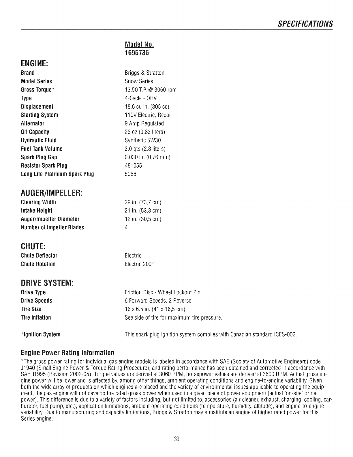
ENGINE:
Brand
Model Series
GrossTorque*
Type
Displacement
Starting System
Alternator
Oil Capacity
Hydraulic Fluid
Fuel TankVolume
Spark Plug Gap
ResistorSpark Plug
LongLife Piatinium Spark Plug
IViodeiNo.
1695735
Briggs & Stratton
Snow Series
13.50 T.R @3060 rpm
4-Cycle - OHV
18.6 cu in. (305 cc)
110V Electric, Recoil
9 Amp Regulated
28 oz (0,83 liters)
Synthetic 5W30
3.0 qts (2.8 liters)
0.030 in. (0,76 mm)
481055
5066
AUGER/IMPELLER:
Clearing Width
intake Height
Auger/Impeller Diameter
Number of Impeller Blades
29 in. (73,7 cm)
21 in. (53,3 cm)
12 in. (30,5 cm)
4
CHUTE:
Chute Deflector
Chute Rotation
Electric
Electric 200°
DRIVESYSTEM:
Drive Type
Drive Speeds
Tire Size
Tire Inflation
*ignition System
Friction Disc - Wheel Lockout Pin
6 ForwardSpeeds,2 Reverse
16 x 6.5 in. (41 x 16,5 cm)
Seeside of tire for maximum tire pressure.
This spark plug ignition system complies with Canadianstandard ICES-002.
EnginePower Rating information
*The gross power rating for individual gas engine models is labeledin accordancewith SAE(Society of Automotive Engineers) code
J1940 (Small Engine Power & Torque Rating Procedure),and rating performancehas beenobtained and corrected in accordance with
SAEJ1995 (Revision 2002-05). Torquevalues are derived at 3060 RPM; horsepower valuesare derived at 3600 RPM. Actual gross en-
gine power will be lower and is affected by,among other things, ambient operating conditions and engine-to-engine variability. Given
both the wide array of products on which engines are placed and the variety of environmental issuesapplicable to operating the equip-
ment, the gas enginewill not develop the rated gross powerwhen used in a given piece of power equipment (actual"on-site" or net
power). This difference is due to a variety of factors including, but not limited to, accessories (air cleaner,exhaust,charging, cooling, car-
buretor, fuel pump, etc.), application limitations, ambient operating conditions (temperature, humidity, altitude), and engine-to-engine
variability. Dueto manufacturing and capacity limitations, Briggs & Stratton maysubstitute an engine of higher rated power for this
Series engine.
33

34

35

Briggs & Stratton Power Products Group, LLC.
Copyright © 2009 Briggs & Stratton Corporation
Milwaukee, WI USA. All Rights Reserved
www. BRIGGSandSTRATTON.com
www.snapper.com
36
