Sno Way 96106472 Joystick Snow Plow Controller User Manual Manual

Sno-Way International, Inc. Joystick Snow Plow Controller Manual
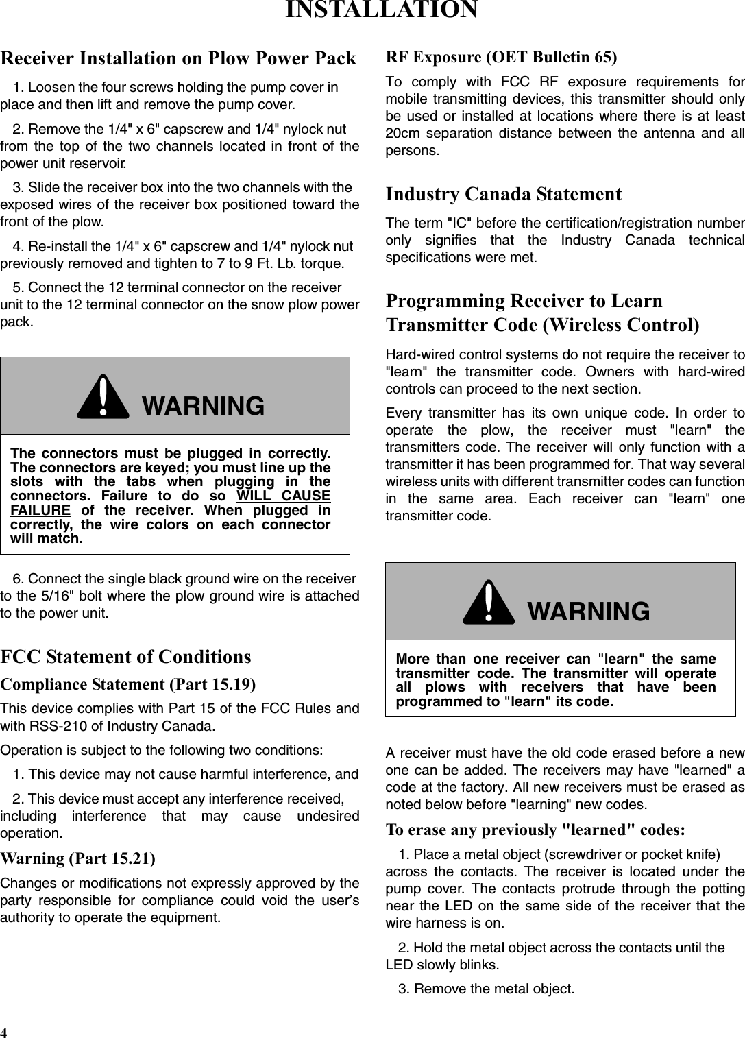
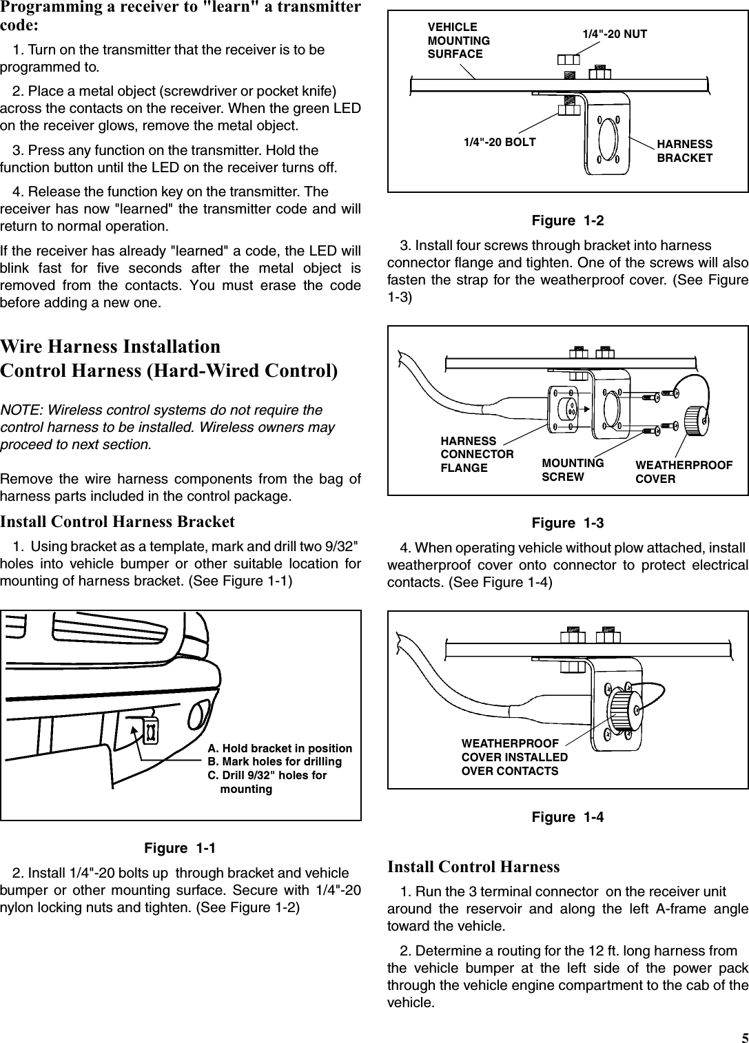
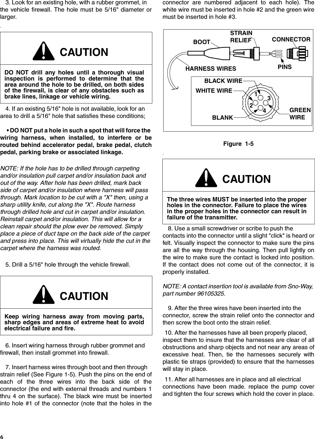
Manual

 OWNER’SINSTALLATIONAND OPERATION MANUAL©2004  Sno-Way® InternationalPLOW CONTROL PACKAGEFOR PLOW SERIAL NUMBERS AFTERSTD200000, STG20000MTD200000, MTG20000HTD200000, HTG20000HTV200000, HTVG1000032C100000, 32D10000, 32G1000026D10000, 26G1000028V10000, 28VG1000097100737F
1TABLE OF CONTENTSTABLE OF CONTENTS .............................................................................................  1INTRODUCTION ......................................................................................................   2SAFETY ..................................................................................................................... 3INSTALLATION .........................................................................................................  4Receiver Installation on Plow Power Pack .....................................................  4FCC Statement of Conditions........................................................................... 4Industry Canada Statement .............................................................................. 4Programming Receiver to Learn Transmitter Code (Wireless Control)........ 4Wire Harness Installation, Control Harness (Hard-Wired Control)...............  5   Install Control Harness Bracket .................................................................... 5   Install Control Harness................................................................................... 5OPERATION................................................................................................................ 7        Theory of Operation .........................................................................................  7        Controller Operation.........................................................................................  7   Switches and Functions - Straight Blade ....................................................  7   Switches and Functions - V Plow.................................................................. 7   Start / Stop Procedure for Hand Held Controller ......................................... 8   Power Saving Mode ........................................................................................ 8Using the Controller to Aid in Mounting and Removing the Snow Plow.....  8WIRING SCHEMATIC (STRAIGHT BLADE - DOWN PRESSURE SYSTEM)  .......... 9WIRING SCHEMATIC (STRAIGHT BLADE - GRAVITY DOWN SYSTEM) ............. 10WIRING SCHEMATIC (V PLOW).............................................................................. 11WARRANTY.......................................................................................... BACK COVERTABLE OF CONTENTSPage
2This manual was written for the assembly, installation andmaintenance of your new Sno-Way plow. Mostimportantly, this manual provides an operating plan forsafe use. Refer to the Table of Contents for an outline ofthis manual.Please keep this manual with your machine at all times asreference material and so it can be passed on to the nextowner if the machine is sold.We require that you read and understand the contents ofthis manual COMPLETELY, especially the chapter onSAFETY, before attempting any procedure contained inthis manual.The Society of Automotive Engineers has adoptedthis SAFETY ALERT SYMBOL to pinpoint characteris-tics that, if NOT carefully followed, can create a safetyhazard. When you see this symbol in this manual oron the machine itself, BE ALERT!, your personalsafety and the safety of others, is involved.• Defined in the next column, are the SAFETY ALERT messages and how they will appear in this manual.NOTE: Additional information concerning the equipment or the procedure that may or may not be contained elsewhere in this manual.BE AWARE! It is illegal to remove, deface or otherwisealter the safety decals mounted on this equipment.Record the Controller Serial Number And The ReceiverSerial Number in the space provided below as a handyrecord for quick reference. The Controller Serial Number islocated on the bottom side of the controller, the Receiverserial number is located on the upper edge of the receiver.This plate contains information that your Dealer needs toanswer questions or to order replacement parts, if needed,for your unit.We reserve the right to make changes or improve thedesign or construction of any part(s) without incurring theobligation to install such parts or make any changes onany unit previously delivered.WARNINGFAILURE TO HEED CAN RESULT IN SERIOUS INJURY OR DEATH.CAUTIONInformation, that if not carefully followed, cancause minor injury or damage to equipment!DEALERNAMEPHONE (         ) –ADDRESSCITY STATE ZIP(FILL IN)ORIGINAL PURCHASERNAMEPHONE (           ) –ADDRESSCITY STATE ZIP(FILL IN)NAME PLATE DATA(FILL IN)CONTROLLER SERIAL NUMBERRECEIVER SERIAL NUMBERINTRODUCTION
SAFETYBEFORE ATTEMPTING ANY PROCEDURE IN THISBOOK, READ AND UNDERSTAND ALL THE SAFETYINFORMATION CONTAINED IN THIS SECTION. INADDITION, ENSURE ALL INDIVIDUALS WORKINGWITH YOU ARE ALSO FAMILIAR WITH THESESAFETY PRECAUTIONS.For your safety Warning and Information Decals havebeen placed on this product to remind the operatorto take safety precautions. It is important that thesedecals are in place and are legible before operationbegins. New decals can be obtained from Sno-Way oryour local dealer.REMEMBER  The careful operator is the bestoperator. Most accidents are caused by human error.Certain precautions must be observed to prevent thepossibility of injury to operator or bystanders and/ordamage to equipment.NEVER  operate plow when under the influence ofalcohol, drugs or other medications that could hamperyour judgement and reactions. An accident may result inserious injury or death to other persons or yourself.ALWAYS operate vehicle in a well-ventilated area. Thecarbon monoxide in exhaust gas is highly toxic and cancause serious injury or death.NEVER  allow hands, hair or clothing to get near anymoving parts such as fan blades, belts and pulleys. Neverwear neckties or loose clothing when working on thevehicle.NEVER wear wrist watches, rings or other jewelry whenworking on the vehicle or individual equipment. Thesethings can catch on moving parts or cause an electricalshort circuit that could result in serious personal injury.ALWAYS  wear safety goggles when working on thevehicle to protect your eyes from battery acid, gasoline,and dust or dirt from flying off of moving engine parts.ALWAYS  be aware of and avoid contact with hotsurfaces such as engine, radiator, and hoses.ALWAYS  wear safety glasses with side shields whenstriking metal against metal! In addition, it isrecommended that a softer (non-chipable) metal materialbe used to cushion the blow. Failure to heed could resultin serious injury to the eye(s) or other parts of the body.NEVER  allow children or unauthorized person tooperate this unit.NEVER exceed 45 m.p.h. when snow plow is attachedto vehicle. Braking distances may be reduced andhandling characteristics may be impaired at speedsabove 45 m.p.h.ALWAYS  lock the vehicle when unattended to preventunauthorized operation of the plow.ALWAYS  check the job site for terrain hazards,obstructions and people.NEVER  exceed 10 m.p.h. when plowing. Excessivespeed may cause serious injury and damage ofequipment and property if an unseen obstacle isencountered while plowing.ALWAYS  position blade so it does not block path ofheadlamps beam. Do not change blade positions whiletraveling. An incorrect plow position blocking headlampbeam may result in an accident.ALWAYS  check surrounding area for hazardousobstacles before operating this unit.ALWAYS inspect the unit periodically for defects. Partsthat are broken, missing or plainly worn must be replacedimmediately. The unit, or any part of it should not bealtered without prior written approval of the manufacturer.ALWAYS  insert the cylinder lock when plow is not inuse. If the cylinder lock is not installed, the plow bladecould inadvertently drop and cause serious injury.ALWAYS  shut off the vehicle engine, place thetransmission in Neutral or Park, turn the ignition switch tothe “OFF” position, firmly apply the parking brake of thevehicle and turn "OFF" the plow controller beforeattaching or detaching the blade from the vehicle or whenmaking adjustments to the blade.ALWAYS  inspect lift system bolts and pins wheneverattaching or detaching the plow, and before traveling.Worn or damaged components could result in the plowdropping to the pavement while driving, causing anaccident.ALWAYS  keep hands and feet clear of blade andA-Frame when attaching or detaching plow.NEVER place fingers in A-frame or mount lug holes tocheck alignment when attaching snow plow. Suddenmotion of the plow could severely injure a finger.NEVER stand between the vehicle and blade or directlyin front of blade when it is being raised, lowered orangled. Clearance between vehicle and blade decreasesas blade is operated and serious injury or death canresult from blade striking a body or dropping on hands orfeet.NEVER  work on the vehicle without having a fullyserviced fire extinguisher available. A 5 lb or larger CO2or dry chemical unit specified for gasoline, chemical orelectrical fires, is recommended.NEVER  smoke while working on the vehicle. Gasolineand battery acid vapors are extremely flammable andexplosive.NEVER  use your hands to search for hydraulic fluidleaks; escaping fluid under pressure can be invisible andcan penetrate the skin and cause a serious injury! If anyfluid is injected into the skin, see a doctor at once!Injected fluid MUST be surgically removed by a doctorfamiliar with this type of injury or gangrene may result.REMEMBER  it is the owner’s responsibility forcommunicating information on the safe use andproper maintenance of this machine.3
4Receiver Installation on Plow Power Pack1. Loosen the four screws holding the pump cover in place and then lift and remove the pump cover.2. Remove the 1/4" x 6" capscrew and 1/4" nylock nut from the top of the two channels located in front of thepower unit reservoir.3. Slide the receiver box into the two channels with the exposed wires of the receiver box positioned toward thefront of the plow.4. Re-install the 1/4" x 6" capscrew and 1/4" nylock nut previously removed and tighten to 7 to 9 Ft. Lb. torque.5. Connect the 12 terminal connector on the receiver unit to the 12 terminal connector on the snow plow powerpack.6. Connect the single black ground wire on the receiver to the 5/16" bolt where the plow ground wire is attachedto the power unit.FCC Statement of ConditionsCompliance Statement (Part 15.19)This device complies with Part 15 of the FCC Rules andwith RSS-210 of Industry Canada.Operation is subject to the following two conditions:1. This device may not cause harmful interference, and2. This device must accept any interference received, including interference that may cause undesiredoperation.Warning (Part 15.21)Changes or modifications not expressly approved by theparty responsible for compliance could void the user’sauthority to operate the equipment.RF Exposure (OET Bulletin 65)To comply with FCC RF exposure requirements formobile transmitting devices, this transmitter should onlybe used or installed at locations where there is at least20cm separation distance between the antenna and allpersons.Industry Canada StatementThe term "IC" before the certification/registration numberonly signifies that the Industry Canada technicalspecifications were met.Programming Receiver to Learn Transmitter Code (Wireless Control)Hard-wired control systems do not require the receiver to"learn" the transmitter code. Owners with hard-wiredcontrols can proceed to the next section.Every transmitter has its own unique code. In order tooperate the plow, the receiver must "learn" thetransmitters code. The receiver will only function with atransmitter it has been programmed for. That way severalwireless units with different transmitter codes can functionin the same area. Each receiver can "learn" onetransmitter code.A receiver must have the old code erased before a newone can be added. The receivers may have "learned" acode at the factory. All new receivers must be erased asnoted below before "learning" new codes.To erase any previously "learned" codes:1. Place a metal object (screwdriver or pocket knife) across the contacts. The receiver is located under thepump cover. The contacts protrude through the pottingnear the LED on the same side of the receiver that thewire harness is on.2. Hold the metal object across the contacts until the LED slowly blinks.3. Remove the metal object.WARNINGThe connectors must be plugged in correctly.The connectors are keyed; you must line up theslots with the tabs when plugging in theconnectors. Failure to do so WILL CAUSEFAILURE of the receiver. When plugged incorrectly, the wire colors on each connectorwill match.WARNINGMore than one receiver can "learn" the sametransmitter code. The transmitter will operateall plows with receivers that have beenprogrammed to "learn" its code.INSTALLATION
5Programming a receiver to "learn" a transmittercode:1. Turn on the transmitter that the receiver is to be programmed to.2. Place a metal object (screwdriver or pocket knife) across the contacts on the receiver. When the green LEDon the receiver glows, remove the metal object.3. Press any function on the transmitter. Hold the function button until the LED on the receiver turns off.4. Release the function key on the transmitter. The receiver has now "learned" the transmitter code and willreturn to normal operation.If the receiver has already "learned" a code, the LED willblink fast for five seconds after the metal object isremoved from the contacts. You must erase the codebefore adding a new one.Wire Harness Installation Control Harness (Hard-Wired Control)NOTE: Wireless control systems do not require the control harness to be installed. Wireless owners may proceed to next section.Remove the wire harness components from the bag ofharness parts included in the control package.Install Control Harness Bracket1.  Using bracket as a template, mark and drill two 9/32" holes into vehicle bumper or other suitable location formounting of harness bracket. (See Figure 1-1)Figure  1-12. Install 1/4"-20 bolts up  through bracket and vehicle bumper or other mounting surface. Secure with 1/4"-20nylon locking nuts and tighten. (See Figure 1-2)Figure  1-23. Install four screws through bracket into harness connector flange and tighten. One of the screws will alsofasten the strap for the weatherproof cover. (See Figure1-3)Figure  1-34. When operating vehicle without plow attached, install weatherproof cover onto connector to protect electricalcontacts. (See Figure 1-4)Figure  1-4Install Control Harness1. Run the 3 terminal connector  on the receiver unit around the reservoir and along the left A-frame angletoward the vehicle.2. Determine a routing for the 12 ft. long harness from the vehicle bumper at the left side of the power packthrough the vehicle engine compartment to the cab of thevehicle.A. Hold bracket in positionB. Mark holes for drillingC. Drill 9/32" holes for    mountingVEHICLEMOUNTING SURFACEHARNESSBRACKET1/4"-20 BOLT1/4"-20 NUTHARNESSCONNECTORFLANGE WEATHERPROOFCOVERMOUNTINGSCREWWEATHERPROOFCOVER INSTALLEDOVER CONTACTS
63. Look for an existing hole, with a rubber grommet, in the vehicle firewall. The hole must be 5/16" diameter orlarger..4. If an existing 5/16" hole is not available, look for an area to drill a 5/16" hole that satisfies these conditions; • DO NOT put a hole in such a spot that will force the wiring harness, when installed, to interfere or berouted behind accelerator pedal, brake pedal, clutchpedal, parking brake or associated linkage.NOTE: If the hole has to be drilled through carpeting and/or insulation pull carpet and/or insulation back and out of the way. After hole has been drilled, mark back side of carpet and/or insulation where harness will pass through. Mark location to be cut with a "X" then, using a sharp utility knife, cut along the "X". Route harness through drilled hole and cut in carpet and/or insulation. Reinstall carpet and/or insulation. This will allow for a clean repair should the plow ever be removed. Simply place a piece of duct tape on the back side of the carpet and press into place. This will virtually hide the cut in the carpet where the harness was routed.5. Drill a 5/16" hole through the vehicle firewall.6. Insert wiring harness through rubber grommet and firewall, then install grommet into firewall.7. Insert harness wires through boot and then through strain relief (See Figure 1-5). Push the pins on the end ofeach of the three wires into the back side of theconnector (the end with external threads and numbers 1thru 4 on the surface). The black wire must be insertedinto hole #1 of the connector (note that the holes in theconnector are numbered adjacent to each hole). Thewhite wire must be inserted in hole #2 and the green wiremust be inserted in hole #3.Figure  1-5.8. Use a small screwdriver or scribe to push the contacts into the connector until a slight "click" is heard orfelt. Visually inspect the connector to make sure the pinsare all the way through the housing. Then pull lightly onthe wire to make sure the contact is locked into position.If the contact does not come out of the connector, it isproperly installed.NOTE: A contact insertion tool is available from Sno-Way, part number 96105325.9. After the three wires have been inserted into the connector, screw the strain relief onto the connector andthen screw the boot onto the strain relief.10. After the harnesses have all been properly placed, inspect them to insure that the harnesses are clear of allobstructions and sharp objects and not near any areas ofexcessive heat. Then, tie the harnesses securely withplastic tie straps (provided) to ensure that the harnesseswill stay in place.11. After all harnesses are in place and all electrical connections have been made. replace the pump coverand tighten the four screws which hold the cover in place.CAUTIONDO NOT drill any holes until a thorough visualinspection is performed to determine that thearea around the hole to be drilled, on both sidesof the firewall, is clear of any obstacles such asbrake lines, linkage or vehicle wiring.CAUTIONKeep wiring harness away from moving parts,sharp edges and areas of extreme heat to avoidelectrical failure and fire.CAUTIONThe three wires MUST be inserted into the properholes in the connector. Failure to place the wiresin the proper holes in the connector can result infailure of the transmitter.1243BLACK WIREWHITE WIREBLANKGREENWIREHARNESS WIRESBOOTSTRAINCONNECTORPINSRELIEF
7Theory of Operation1. The Sno-Way Snow Plow Control System includes a hand held controller. When a switch is actuated, thecontroller sends a signal out to the snow plow through theplow control harness indicating which operation is to beperformed, such as ’Raise’, ’Swing Right’ and ’DP On’.2. The second key part of the Control System is the receiver on the plow. It receives the signal from the handheld controller and processes the signal to open or closethe proper electrical switches to turn solenoids andvalves on or off so that the hydraulic system of the plowpower unit will perform the required operations.3. 12V DC power is fed into the receiver from the battery terminal of the start solenoid. 12V DC power is then fedout of the receiver to the start solenoid primary circuitand to the coils of the valve solenoids. The ground wiresfor the start solenoid primary circuit and the coils of thevalve solenoids return to the circuit board of the receiverwhere switches on the circuit board open or close theground to complete or break the circuit to each coil andsolenoid.4. A low voltage power circuit leads from the receiver to the hand held controller. This powers the circuit board ofthe hand held controller and supplies the low voltagepower needed to process the signal from the switches onthe hand held unit and send a signal back to the receiveron the plow.Controller OperationFunctions - Handheld Straight BladeThe hand held controller contains all of the controlfunctions necessary for the operation of your Sno-Waysnow plow. The curved rocker switch in the center of thetouchpad controls the ’Raise’ and ’Lower’ functions.Pressing the forward portion of the rocker switch will’Raise’ the plow. Pressing the rearward portion of therocker switch will ’Lower’ the plow. Pressing the raisedswitch on the right side of the touchpad will swing theblade to the right. Pressing the raised switch on the leftside of the touchpad will swing the blade to the left. Theround button in the lower center is the ’Down Pressure’switch. Pressing the switch will turn on the down pressure,and a red indicator light in the center of the switch willglow. Pressing the switch again will turn the downpressure off. The round button in the lower right is the’On-Off’ switch. A green indicator light in the center of theswitch will glow when the controller is ’On’. The roundbutton in the lower left has no function at this time, andwas designed into the controller for possible future use.Functions - Joystick Straight BladeThe joystick controller contains all of the control functionsnecessary for the operation of your Sno-Way snowplow.The joystick on the top of the controller controls the’Raise’, ’Lower’, and ’Angle’ functions. Pulling the joysticktoward you will ’Raise’ the plow. Pushing the joystickaway from you will ’Lower’ the plow. Moving the joystick tothe right will swing the blade to the right. Moving thejoystick to the left will swing the blade to the left. There aretwo buttons on the front of the controller. The button onthe right is the ’Down Pressure’ button. Pressing the downpressure button will turn on the down pressure, and a redindicator on the top right corner of the controller will glow.Pressing the button again will turn the down pressure off.The button on the left is the power button. A yellowindicator light on the top left of the controller will glowwhen the controller is ’On’.Functions - Handheld V PlowThe hand held controller contains all of the controlfunctions necessary for the operation of your Sno-Waysnow plow. The curved rocker switch in the center of thetouchpad controls the ‘Raise’ and ‘Lower’ functions.Pressing the forward portion of the rocker switch will‘Raise’ the plow. Pressing the rearward portion of therocker switch will ‘Lower’ the plow. There are four raisedswitches that surround the ‘Raise-Lower’ rockers switch.To move the plow so both wings angle right press the tworight switches at the same time. To move the plow so bothwings angle left, press the two left switches at the sametime. To ‘Scoop’ or ‘Vee Forward’ press the top two leftand right switches at the same time. To ‘Vee Backward’press the bottom two left and right switches at the sametime. Either wing can be moved independently. To movethe right wing forward, press the top right button. To movethe right wing backward, press the bottom right button.The left side operation is just the opposite of the right side.The round button in the lower center is the ‘DownPressure’ switch. Pressing the switch will turn on thedown pressure, and a red indicator light in the center ofthe switch will glow. Pressing the switch again will turn thedown pressure off and return the plow into float mode. Theround button in the lower right is the ‘On-Off’ switch. Agreen indicator light in the center of the switch will glowwhen the controller is ‘On’. The round button in the lowerleft has no function at this time, and was designed into thecontroller for possible future useFunctions - Joystick V PlowThe joystick controller contains all of the control functionsnecessary for the operation of your Sno-Way snowplow.The joystick on the top left side of the controller controlsthe ’Raise’ and ’Lower’ functions. Pulling the joysticktoward you will ’Raise’ the plow. Pushing the joystickaway from you will ’Lower’ the plow. The joystick on theOPERATION
8top right side controls the wings. To move the plow soboth wings angle right, move the joystick to the right. Tomove the plow so both wings angle left, move the joystickto the left. To ’Scoop’ or ’Vee Forward’, push the joystickaway from you. To ’Vee Backward’, pull the joysticktoward you. Either wing can be moved independently.Pushing the joystick forward and to the left will move theleft wing forward. Pulling the joystick back and to the leftwill move the left wing backward. Pushing the joystickforward and to the right will move the right wing forward.Pulling the joystick back and to the right will move the rightwing backward. There are two buttons on the front of thecontroller. The button on the right is the ’Down Pressure’button. Pressing the down pressure button will turn on thedown pressure and a red indicator on the top right of thecontroller will glow. Pressing the switch again will turn thedown pressure off. The button on the left is the powerbutton. A yellow indicator light on the top left of thecontroller will glow when the controller in ’On’.Start/Stop Procedure for ControllersTo prevent the controller from inadvertently andaccidentally being switched on or off, a sequence isrequired to turn the controller on or off.To turn the controller ’On’, press the ’On-Off’ or ’Power’button and ’Down Pressure’ button at the same time. Agreen or yellow indicator will glow to indicate that thecontroller is ’On’.To turn the controller ’Off’, press and hold the ’On-Off’ or’Power’ button for one second. The controller will turn offand the yellow or green indicator will stop glowing.Power Saving ModeThe hand held controller uses a very small amount ofelectrical current anytime it is ’On’. To minimize currentuse when the controller is inactive, the system has a’Sleep’ mode to shut itself down. If no control function ispressed for a time period of approximately 60 minutes, thecontroller will shut down by itself. When this happens, thestart sequence procedure must be used to re-start thecontroller.Using the Controller to Aid in Mounting andRemoving the Snow PlowThe hand held controller can be used near the snow plowwhen mounting or removing the plow with the aid of thepower jackstand. NOTE: For proper procedure in mounting and removal of the snow plow, refer to your Sno-Way plow Owner’s Manual.For Hard-Wired UnitsDisconnect the cable for the hand held controller at theharness connection inside the vehicle cab and take thecontroller to the front of the vehicle. Disconnect the plowcontrol harness from the vehicle control harness at theconnector at the front of the vehicle. Connect the handheld controller harness to the plow control harness. Thehand held controller can now be used just as it is normallyused in the cab of the vehicle.For Wireless UnitsRemove the hand held controller from the cab, carry it tothe front of the truck and use normally.When plow mounting or removal is completed, disconnectthe hand held controller and, if the plow is being mounted,reconnect the harness of the hand held controller to thevehicle harness connector in the cab.WARNINGWhen using the hand held controller near theplow, be especially careful of the movement ofany plow components when any switch on thecontroller is actuated. Stand clear of the snowplow at all times to avoid being struck by anyplow parts.FAILURE TO HEED CAN RESULT IN SERIOUSINJURY OR DEATH.
9WIRING SCHEMATIC(STRAIGHT BLADE - DOWN PRESSURE SYSTEM)
10WIRING SCHEMATIC(STRAIGHT BLADE - GRAVITY DOWN SYSTEM)
11WIRING SCHEMATIC(V PLOW)
SNO-WAY PLOWS - LIMITED WARRANTYFIVE YEAR STRUCTURAL LIMITED WARRANTY COVERAGEThe Sno-Way snow plow structural elements are warranted to be free from defects in materials and workmanship for a period of five years from date ofdelivery from an authorized Sno-Way Dealer. The Sno-Way Warranty Registration card for the product must be properly filled out and mailed toSno-Way within 30 days of date of purchase to obtain benefits of this section of warranty. Structural elements are defined for this warranty as: Blade frames, A-frames, Swing Frames, vehicle sub frames, and structural components(weldments) of Sno-Way snow plows.TWO YEAR STANDARD LIMITED WARRANTY COVERAGEThe Sno-Way snow plow nonstructural components are warranted to be free from defects in workmanship for a period of two years from date of deliveryfrom an authorized Sno-Way Dealer. The Sno-Way Warranty Registration card for the product must be properly filled out and mailed to Sno-Way within30 days of date of purchase to obtain the benefits of this section of warranty.Nonstructural product components are defined for this warranty as: Blade inserts (Lexan/Hyzod or steel) and the SM01 Hydraulic power systemand control module.ONE YEAR STANDARD LIMITED WARRANTYACCESORIES / SERVICE PARTS / COMPONENTS.Sno-Way International, Inc. Warrants accessories, service parts and components purchased separately for a period of one year after original purchaseto be free from defects in material and workmanship.DEFINITION OF PRODUCT:Product as used throughout this warranty means the Sno-Way line of Predator snow plows, straight blades ans "V" blades and components thereof.EXCLUSIONS UNDER THIS WARRANTY PROGRAM:1. The installation of product must be an approved installation in accordance with the Sno-Way Vehicle Application Guide, Installation InstructionsManual and the Owner’s Manual.2. The "use" of the Sno-Way product must be in conformity with the operating and maintenance instructions as set forth in the Owner’s Manual.3. Damage as a result of accident, misuse and/or negligence is not covered.4. The polycarbonate moldboard under the two year warranty does not cover: Puncture, Hazing, Abrasion, Yellowing, Scratching or Chemical Damage.5. Normal wear items are excluded (Without limitation): Paint finish-corrosion/contamination, Bushings and bearings, Plow shoes, Plow cutting edges,Blade markers/pins/clips, Accessory items and non-standard attachments - or any damage caused by the addition of non-standard attachments notsold by Sno-Way.6. Specific exclusions relating to items covered under the Two Year Warranty: Fasteners and damage caused by failure to retighten fasteners, Electriccontact corrosion - damage or abrasion of wiring harness, Control key pads/contacts, Any damage resulting from a failure to properly service andmaintain the product as prescribed in the Owner’s Manual.7. General exclusions:(A) Any and all damage from the improper installation of product, misapplication of product, abusive use of vehicle and/or product, failure to properlymaintain and service, improper repair, service or alteration of product, and any damage as a result of accident or misuse.(B) Sno-Way will not be liable for any expense not related to defects in materials and workmanship. The attachment of product to or upon a vehicle,including any necessary modification of product or vehicle, is entirely at the purchasers risk and expense, and compliance with applicable motor vehiclerules and regulations is the responsibility of the installer.(C) This Warranty when applicable applies to the "first" purchaser of product installed in accordance with Sno-Way Application Guides, Installation andOwner’s Manuals, and to the transfer of the product by the "first" purchaser to another approved vehicle application by an authorized Sno-Way Dealer.(D) The "repair" and/or replacement of any part or component is at the option of Sno-Way.(E) Indirect costs incurred while "product" is being repaired during the warranty period are excluded such as; lost time, equipment rental, transportationcharges, and similar incidental charges incurred.OBTAINING WARRANTY SERVICETo obtain warranty service, promptly return the product or any defective part at your expense to any authorized Sno-Way Dealer during the warrantyperiod. Replacement or repair of defective or inadequate parts shall be performed without charge for labor or materials by such Dealer at his regularplace of business during regular business hours after inspection and determination that the warranty applies.Purchaser shall prepay all freight charges for returning Product or component to Dealer, Sno-Way or any other location designated by Sno-Way.Note: The Sno-Way Technical Services help line is designed to service Sno-Way Dealers. Sno-Way Technical and Customer Service will help youlocate your nearest Sno-Way Dealer.Please also use the Sno-Way web site with the Dealer locator: www.snoway.comDISCLAIMERS:1. Sno-Way warrants it’s Products only as set forth in this warranty. Sno-Way makes no other warranties, express or implied, and disclaims all otherwarranties, including any implied warranty of merchantability or fitness for any particular purpose.2. Sno-Way’s obligations under this warranty are limited to those expressed in this warranty, and Sno-Way shall not be liable to the purchaser or anythird party for any direct or indirect, incidental or consequential damage or loss.3. No person is authorized to modify or add to this warranty in any manner.4. If any Sno-Way product is improperly installed, altered, misused, damaged or otherwise tampered with, this warranty shall lapse and become null andvoid.LEGAL RIGHTS:Some states do not allow limitations on how long an implied warranty lasts or exclusions or limitations of incidental or consequential damages, so theabove limitations or exclusions may not apply fully to you. This w arranty gives you specific legal rights, and you may also have other rights which varyfrom state to state. All "other" provisions and "limitations" not altered by local law shall continue to apply.ENFORCEMENT/CONSTRUCTIONThis Warranty shall be enforced and construed under the laws of the State of Wisconsin.SNO-WAY INTERNATIONAL, INC.SNO-WAY® INTERNATIONAL, INC.Hartford, WI 53027 USAWebsite: www.snoway.com©2004 Sno-Way® International

Navigation menu