Sno Way 96106472 Joystick Snow Plow Controller User Manual Manual
Sno-Way International, Inc. Joystick Snow Plow Controller Manual
Sno Way >
Manual

OWNER’S
INSTALLATION
AND OPERATION MANUAL
©2004 Sno-Way® International
PLOW CONTROL PACKAGE
FOR PLOW SERIAL NUMBERS AFTER
STD200000, STG20000
MTD200000, MTG20000
HTD200000, HTG20000
HTV200000, HTVG10000
32C100000, 32D10000, 32G10000
26D10000, 26G10000
28V10000, 28VG10000
97100737F

1
TABLE OF CONTENTS
TABLE OF CONTENTS ............................................................................................. 1
INTRODUCTION ...................................................................................................... 2
SAFETY ..................................................................................................................... 3
INSTALLATION ......................................................................................................... 4
Receiver Installation on Plow Power Pack ..................................................... 4
FCC Statement of Conditions........................................................................... 4
Industry Canada Statement .............................................................................. 4
Programming Receiver to Learn Transmitter Code (Wireless Control)........ 4
Wire Harness Installation, Control Harness (Hard-Wired Control)............... 5
Install Control Harness Bracket .................................................................... 5
Install Control Harness................................................................................... 5
OPERATION................................................................................................................ 7
Theory of Operation ......................................................................................... 7
Controller Operation......................................................................................... 7
Switches and Functions - Straight Blade .................................................... 7
Switches and Functions - V Plow.................................................................. 7
Start / Stop Procedure for Hand Held Controller ......................................... 8
Power Saving Mode ........................................................................................ 8
Using the Controller to Aid in Mounting and Removing the Snow Plow..... 8
WIRING SCHEMATIC (STRAIGHT BLADE - DOWN PRESSURE SYSTEM) .......... 9
WIRING SCHEMATIC (STRAIGHT BLADE - GRAVITY DOWN SYSTEM) ............. 10
WIRING SCHEMATIC (V PLOW).............................................................................. 11
WARRANTY.......................................................................................... BACK COVER
TABLE OF CONTENTS
Page
2
This manual was written for the assembly, installation and
maintenance of your new Sno-Way plow. Most
importantly, this manual provides an operating plan for
safe use. Refer to the Table of Contents for an outline of
this manual.
Please keep this manual with your machine at all times as
reference material and so it can be passed on to the next
owner if the machine is sold.
We require that you read and understand the contents of
this manual COMPLETELY, especially the chapter on
SAFETY, before attempting any procedure contained in
this manual.
The Society of Automotive Engineers has adopted
this SAFETY ALERT SYMBOL to pinpoint characteris-
tics that, if NOT carefully followed, can create a safety
hazard. When you see this symbol in this manual or
on the machine itself, BE ALERT!, your personal
safety and the safety of others, is involved.
• Defined in the next column, are the SAFETY ALERT
messages and how they will appear in this manual.
NOTE: Additional information concerning the equipment
or the procedure that may or may not be contained
elsewhere in this manual.
BE AWARE! It is illegal to remove, deface or otherwise
alter the safety decals mounted on this equipment.
Record the Controller Serial Number And The Receiver
Serial Number in the space provided below as a handy
record for quick reference. The Controller Serial Number is
located on the bottom side of the controller, the Receiver
serial number is located on the upper edge of the receiver.
This plate contains information that your Dealer needs to
answer questions or to order replacement parts, if needed,
for your unit.
We reserve the right to make changes or improve the
design or construction of any part(s) without incurring the
obligation to install such parts or make any changes on
any unit previously delivered.
WARNING
FAILURE TO HEED CAN RESULT IN SERIOUS
INJURY OR DEATH.
CAUTION
Information, that if not carefully followed, can
cause minor injury or damage to equipment!
DEALER
NAME
PHONE ( ) –
ADDRESS
CITY STATE ZIP
(FILL IN)
ORIGINAL PURCHASER
NAME
PHONE ( ) –
ADDRESS
CITY STATE ZIP
(FILL IN)
NAME PLATE DATA
(FILL IN)
CONTROLLER SERIAL NUMBER
RECEIVER SERIAL NUMBER
INTRODUCTION

SAFETY
BEFORE ATTEMPTING ANY PROCEDURE IN THIS
BOOK, READ AND UNDERSTAND ALL THE SAFETY
INFORMATION CONTAINED IN THIS SECTION. IN
ADDITION, ENSURE ALL INDIVIDUALS WORKING
WITH YOU ARE ALSO FAMILIAR WITH THESE
SAFETY PRECAUTIONS.
For your safety Warning and Information Decals have
been placed on this product to remind the operator
to take safety precautions. It is important that these
decals are in place and are legible before operation
begins. New decals can be obtained from Sno-Way or
your local dealer.
REMEMBER The careful operator is the best
operator. Most accidents are caused by human error.
Certain precautions must be observed to prevent the
possibility of injury to operator or bystanders and/or
damage to equipment.
NEVER operate plow when under the influence of
alcohol, drugs or other medications that could hamper
your judgement and reactions. An accident may result in
serious injury or death to other persons or yourself.
ALWAYS operate vehicle in a well-ventilated area. The
carbon monoxide in exhaust gas is highly toxic and can
cause serious injury or death.
NEVER allow hands, hair or clothing to get near any
moving parts such as fan blades, belts and pulleys. Never
wear neckties or loose clothing when working on the
vehicle.
NEVER wear wrist watches, rings or other jewelry when
working on the vehicle or individual equipment. These
things can catch on moving parts or cause an electrical
short circuit that could result in serious personal injury.
ALWAYS wear safety goggles when working on the
vehicle to protect your eyes from battery acid, gasoline,
and dust or dirt from flying off of moving engine parts.
ALWAYS be aware of and avoid contact with hot
surfaces such as engine, radiator, and hoses.
ALWAYS wear safety glasses with side shields when
striking metal against metal! In addition, it is
recommended that a softer (non-chipable) metal material
be used to cushion the blow. Failure to heed could result
in serious injury to the eye(s) or other parts of the body.
NEVER allow children or unauthorized person to
operate this unit.
NEVER exceed 45 m.p.h. when snow plow is attached
to vehicle. Braking distances may be reduced and
handling characteristics may be impaired at speeds
above 45 m.p.h.
ALWAYS lock the vehicle when unattended to prevent
unauthorized operation of the plow.
ALWAYS check the job site for terrain hazards,
obstructions and people.
NEVER exceed 10 m.p.h. when plowing. Excessive
speed may cause serious injury and damage of
equipment and property if an unseen obstacle is
encountered while plowing.
ALWAYS position blade so it does not block path of
headlamps beam. Do not change blade positions while
traveling. An incorrect plow position blocking headlamp
beam may result in an accident.
ALWAYS check surrounding area for hazardous
obstacles before operating this unit.
ALWAYS inspect the unit periodically for defects. Parts
that are broken, missing or plainly worn must be replaced
immediately. The unit, or any part of it should not be
altered without prior written approval of the manufacturer.
ALWAYS insert the cylinder lock when plow is not in
use. If the cylinder lock is not installed, the plow blade
could inadvertently drop and cause serious injury.
ALWAYS shut off the vehicle engine, place the
transmission in Neutral or Park, turn the ignition switch to
the “OFF” position, firmly apply the parking brake of the
vehicle and turn "OFF" the plow controller before
attaching or detaching the blade from the vehicle or when
making adjustments to the blade.
ALWAYS inspect lift system bolts and pins whenever
attaching or detaching the plow, and before traveling.
Worn or damaged components could result in the plow
dropping to the pavement while driving, causing an
accident.
ALWAYS keep hands and feet clear of blade and
A-Frame when attaching or detaching plow.
NEVER place fingers in A-frame or mount lug holes to
check alignment when attaching snow plow. Sudden
motion of the plow could severely injure a finger.
NEVER stand between the vehicle and blade or directly
in front of blade when it is being raised, lowered or
angled. Clearance between vehicle and blade decreases
as blade is operated and serious injury or death can
result from blade striking a body or dropping on hands or
feet.
NEVER work on the vehicle without having a fully
serviced fire extinguisher available. A 5 lb or larger CO2
or dry chemical unit specified for gasoline, chemical or
electrical fires, is recommended.
NEVER smoke while working on the vehicle. Gasoline
and battery acid vapors are extremely flammable and
explosive.
NEVER use your hands to search for hydraulic fluid
leaks; escaping fluid under pressure can be invisible and
can penetrate the skin and cause a serious injury! If any
fluid is injected into the skin, see a doctor at once!
Injected fluid MUST be surgically removed by a doctor
familiar with this type of injury or gangrene may result.
REMEMBER it is the owner’s responsibility for
communicating information on the safe use and
proper maintenance of this machine.
3
4
Receiver Installation on Plow Power Pack
1. Loosen the four screws holding the pump cover in
place and then lift and remove the pump cover.
2. Remove the 1/4" x 6" capscrew and 1/4" nylock nut
from the top of the two channels located in front of the
power unit reservoir.
3. Slide the receiver box into the two channels with the
exposed wires of the receiver box positioned toward the
front of the plow.
4. Re-install the 1/4" x 6" capscrew and 1/4" nylock nut
previously removed and tighten to 7 to 9 Ft. Lb. torque.
5. Connect the 12 terminal connector on the receiver
unit to the 12 terminal connector on the snow plow power
pack.
6. Connect the single black ground wire on the receiver
to the 5/16" bolt where the plow ground wire is attached
to the power unit.
FCC Statement of Conditions
Compliance Statement (Part 15.19)
This device complies with Part 15 of the FCC Rules and
with RSS-210 of Industry Canada.
Operation is subject to the following two conditions:
1. This device may not cause harmful interference, and
2. This device must accept any interference received,
including interference that may cause undesired
operation.
Warning (Part 15.21)
Changes or modifications not expressly approved by the
party responsible for compliance could void the user’s
authority to operate the equipment.
RF Exposure (OET Bulletin 65)
To comply with FCC RF exposure requirements for
mobile transmitting devices, this transmitter should only
be used or installed at locations where there is at least
20cm separation distance between the antenna and all
persons.
Industry Canada Statement
The term "IC" before the certification/registration number
only signifies that the Industry Canada technical
specifications were met.
Programming Receiver to Learn
Transmitter Code (Wireless Control)
Hard-wired control systems do not require the receiver to
"learn" the transmitter code. Owners with hard-wired
controls can proceed to the next section.
Every transmitter has its own unique code. In order to
operate the plow, the receiver must "learn" the
transmitters code. The receiver will only function with a
transmitter it has been programmed for. That way several
wireless units with different transmitter codes can function
in the same area. Each receiver can "learn" one
transmitter code.
A receiver must have the old code erased before a new
one can be added. The receivers may have "learned" a
code at the factory. All new receivers must be erased as
noted below before "learning" new codes.
To erase any previously "learned" codes:
1. Place a metal object (screwdriver or pocket knife)
across the contacts. The receiver is located under the
pump cover. The contacts protrude through the potting
near the LED on the same side of the receiver that the
wire harness is on.
2. Hold the metal object across the contacts until the
LED slowly blinks.
3. Remove the metal object.
WARNING
The connectors must be plugged in correctly.
The connectors are keyed; you must line up the
slots with the tabs when plugging in the
connectors. Failure to do so WILL CAUSE
FAILURE of the receiver. When plugged in
correctly, the wire colors on each connector
will match.
WARNING
More than one receiver can "learn" the same
transmitter code. The transmitter will operate
all plows with receivers that have been
programmed to "learn" its code.
INSTALLATION
5
Programming a receiver to "learn" a transmitter
code:
1. Turn on the transmitter that the receiver is to be
programmed to.
2. Place a metal object (screwdriver or pocket knife)
across the contacts on the receiver. When the green LED
on the receiver glows, remove the metal object.
3. Press any function on the transmitter. Hold the
function button until the LED on the receiver turns off.
4. Release the function key on the transmitter. The
receiver has now "learned" the transmitter code and will
return to normal operation.
If the receiver has already "learned" a code, the LED will
blink fast for five seconds after the metal object is
removed from the contacts. You must erase the code
before adding a new one.
Wire Harness Installation
Control Harness (Hard-Wired Control)
NOTE: Wireless control systems do not require the
control harness to be installed. Wireless owners may
proceed to next section.
Remove the wire harness components from the bag of
harness parts included in the control package.
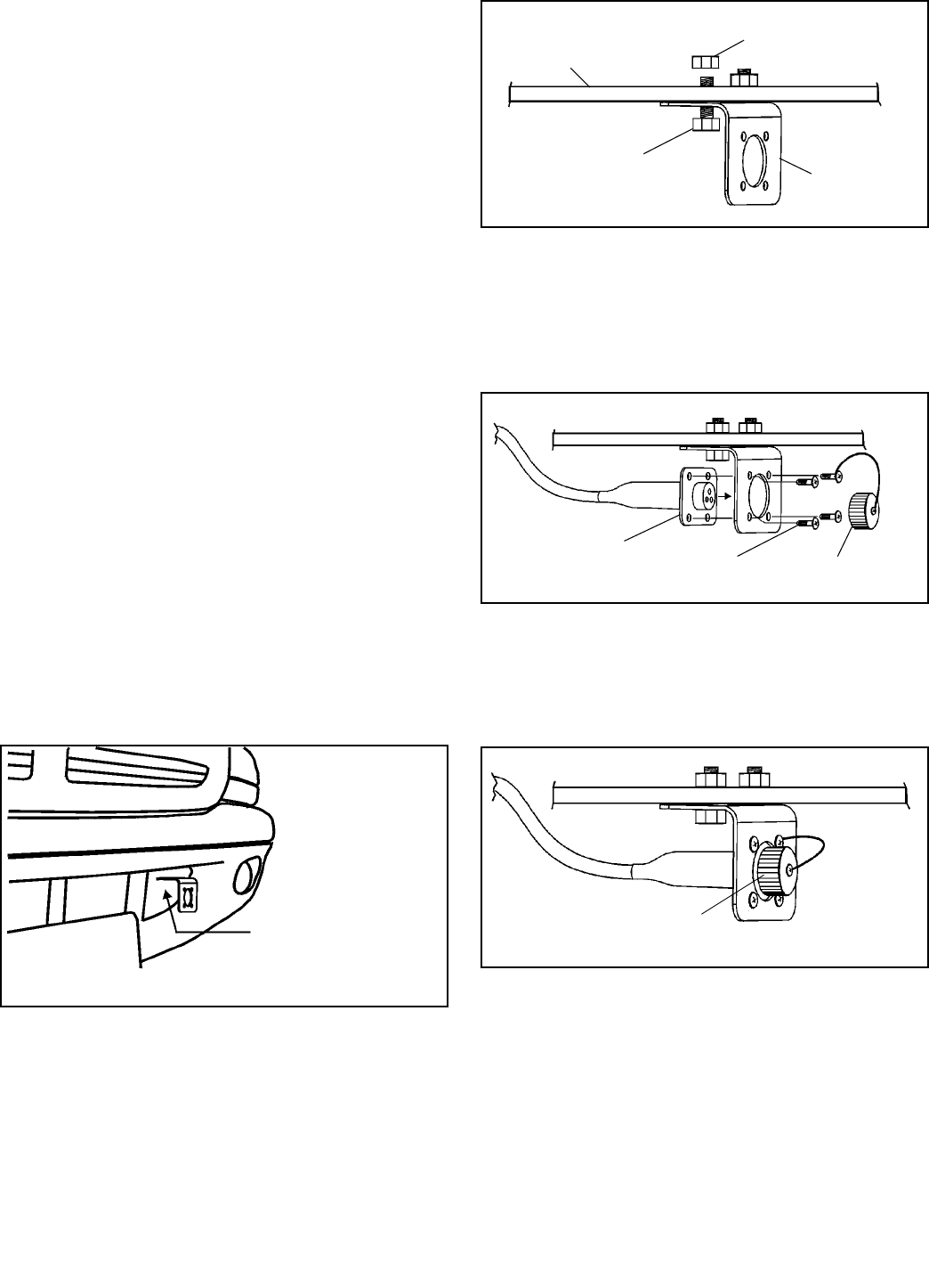
Install Control Harness Bracket
1. Using bracket as a template, mark and drill two 9/32"
holes into vehicle bumper or other suitable location for
mounting of harness bracket. (See Figure 1-1)
Figure 1-1
2. Install 1/4"-20 bolts up through bracket and vehicle
bumper or other mounting surface. Secure with 1/4"-20
nylon locking nuts and tighten. (See Figure 1-2)
Figure 1-2
3. Install four screws through bracket into harness
connector flange and tighten. One of the screws will also
fasten the strap for the weatherproof cover. (See Figure
1-3)
Figure 1-3
4. When operating vehicle without plow attached, install
weatherproof cover onto connector to protect electrical
contacts. (See Figure 1-4)
Figure 1-4
Install Control Harness
1. Run the 3 terminal connector on the receiver unit
around the reservoir and along the left A-frame angle
toward the vehicle.
2. Determine a routing for the 12 ft. long harness from
the vehicle bumper at the left side of the power pack
through the vehicle engine compartment to the cab of the
vehicle.
A. Hold bracket in position
B. Mark holes for drilling
C. Drill 9/32" holes for
mounting
VEHICLE
MOUNTING
SURFACE
HARNESS
BRACKET
1/4"-20 BOLT
1/4"-20 NUT
HARNESS
CONNECTOR
FLANGE WEATHERPROOF
COVER
MOUNTING
SCREW
WEATHERPROOF
COVER INSTALLED
OVER CONTACTS
6
3. Look for an existing hole, with a rubber grommet, in
the vehicle firewall. The hole must be 5/16" diameter or
larger.
.
4. If an existing 5/16" hole is not available, look for an
area to drill a 5/16" hole that satisfies these conditions;
• DO NOT put a hole in such a spot that will force the
wiring harness, when installed, to interfere or be
routed behind accelerator pedal, brake pedal, clutch
pedal, parking brake or associated linkage.
NOTE: If the hole has to be drilled through carpeting
and/or insulation pull carpet and/or insulation back and
out of the way. After hole has been drilled, mark back
side of carpet and/or insulation where harness will pass
through. Mark location to be cut with a "X" then, using a
sharp utility knife, cut along the "X". Route harness
through drilled hole and cut in carpet and/or insulation.
Reinstall carpet and/or insulation. This will allow for a
clean repair should the plow ever be removed. Simply
place a piece of duct tape on the back side of the carpet
and press into place. This will virtually hide the cut in the
carpet where the harness was routed.
5. Drill a 5/16" hole through the vehicle firewall.
6. Insert wiring harness through rubber grommet and
firewall, then install grommet into firewall.
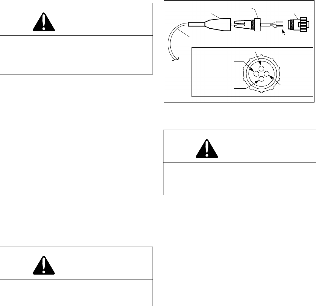
7. Insert harness wires through boot and then through
strain relief (See Figure 1-5). Push the pins on the end of
each of the three wires into the back side of the
connector (the end with external threads and numbers 1
thru 4 on the surface). The black wire must be inserted
into hole #1 of the connector (note that the holes in the
connector are numbered adjacent to each hole). The
white wire must be inserted in hole #2 and the green wire
must be inserted in hole #3.
Figure 1-5
.
8. Use a small screwdriver or scribe to push the
contacts into the connector until a slight "click" is heard or
felt. Visually inspect the connector to make sure the pins
are all the way through the housing. Then pull lightly on
the wire to make sure the contact is locked into position.
If the contact does not come out of the connector, it is
properly installed.
NOTE: A contact insertion tool is available from Sno-Way,
part number 96105325.
9. After the three wires have been inserted into the
connector, screw the strain relief onto the connector and
then screw the boot onto the strain relief.
10. After the harnesses have all been properly placed,
inspect them to insure that the harnesses are clear of all
obstructions and sharp objects and not near any areas of
excessive heat. Then, tie the harnesses securely with
plastic tie straps (provided) to ensure that the harnesses
will stay in place.
11. After all harnesses are in place and all electrical
connections have been made. replace the pump cover
and tighten the four screws which hold the cover in place.
CAUTION
DO NOT drill any holes until a thorough visual
inspection is performed to determine that the
area around the hole to be drilled, on both sides
of the firewall, is clear of any obstacles such as
brake lines, linkage or vehicle wiring.
CAUTION
Keep wiring harness away from moving parts,
sharp edges and areas of extreme heat to avoid
electrical failure and fire.
CAUTION
The three wires MUST be inserted into the proper
holes in the connector. Failure to place the wires
in the proper holes in the connector can result in
failure of the transmitter.
1
24
3
BLACK WIRE
WHITE WIRE
BLANK
GREEN
WIRE
HARNESS WIRES
BOOT
STRAIN
CONNECTOR
PINS
RELIEF

7
Theory of Operation
1. The Sno-Way Snow Plow Control System includes a
hand held controller. When a switch is actuated, the
controller sends a signal out to the snow plow through the
plow control harness indicating which operation is to be
performed, such as ’Raise’, ’Swing Right’ and ’DP On’.
2. The second key part of the Control System is the
receiver on the plow. It receives the signal from the hand
held controller and processes the signal to open or close
the proper electrical switches to turn solenoids and
valves on or off so that the hydraulic system of the plow
power unit will perform the required operations.
3. 12V DC power is fed into the receiver from the battery
terminal of the start solenoid. 12V DC power is then fed
out of the receiver to the start solenoid primary circuit
and to the coils of the valve solenoids. The ground wires
for the start solenoid primary circuit and the coils of the
valve solenoids return to the circuit board of the receiver
where switches on the circuit board open or close the
ground to complete or break the circuit to each coil and
solenoid.
4. A low voltage power circuit leads from the receiver to
the hand held controller. This powers the circuit board of
the hand held controller and supplies the low voltage
power needed to process the signal from the switches on
the hand held unit and send a signal back to the receiver
on the plow.
Controller Operation
Functions - Handheld Straight Blade
The hand held controller contains all of the control
functions necessary for the operation of your Sno-Way
snow plow. The curved rocker switch in the center of the
touchpad controls the ’Raise’ and ’Lower’ functions.
Pressing the forward portion of the rocker switch will
’Raise’ the plow. Pressing the rearward portion of the
rocker switch will ’Lower’ the plow. Pressing the raised
switch on the right side of the touchpad will swing the
blade to the right. Pressing the raised switch on the left
side of the touchpad will swing the blade to the left. The
round button in the lower center is the ’Down Pressure’
switch. Pressing the switch will turn on the down pressure,
and a red indicator light in the center of the switch will
glow. Pressing the switch again will turn the down
pressure off. The round button in the lower right is the
’On-Off’ switch. A green indicator light in the center of the
switch will glow when the controller is ’On’. The round
button in the lower left has no function at this time, and
was designed into the controller for possible future use.
Functions - Joystick Straight Blade
The joystick controller contains all of the control functions
necessary for the operation of your Sno-Way snowplow.
The joystick on the top of the controller controls the
’Raise’, ’Lower’, and ’Angle’ functions. Pulling the joystick
toward you will ’Raise’ the plow. Pushing the joystick
away from you will ’Lower’ the plow. Moving the joystick to
the right will swing the blade to the right. Moving the
joystick to the left will swing the blade to the left. There are
two buttons on the front of the controller. The button on
the right is the ’Down Pressure’ button. Pressing the down
pressure button will turn on the down pressure, and a red
indicator on the top right corner of the controller will glow.
Pressing the button again will turn the down pressure off.
The button on the left is the power button. A yellow
indicator light on the top left of the controller will glow
when the controller is ’On’.
Functions - Handheld V Plow
The hand held controller contains all of the control
functions necessary for the operation of your Sno-Way
snow plow. The curved rocker switch in the center of the
touchpad controls the ‘Raise’ and ‘Lower’ functions.
Pressing the forward portion of the rocker switch will
‘Raise’ the plow. Pressing the rearward portion of the
rocker switch will ‘Lower’ the plow. There are four raised
switches that surround the ‘Raise-Lower’ rockers switch.
To move the plow so both wings angle right press the two
right switches at the same time. To move the plow so both
wings angle left, press the two left switches at the same
time. To ‘Scoop’ or ‘Vee Forward’ press the top two left
and right switches at the same time. To ‘Vee Backward’
press the bottom two left and right switches at the same
time. Either wing can be moved independently. To move
the right wing forward, press the top right button. To move
the right wing backward, press the bottom right button.
The left side operation is just the opposite of the right side.
The round button in the lower center is the ‘Down
Pressure’ switch. Pressing the switch will turn on the
down pressure, and a red indicator light in the center of
the switch will glow. Pressing the switch again will turn the
down pressure off and return the plow into float mode. The
round button in the lower right is the ‘On-Off’ switch. A
green indicator light in the center of the switch will glow
when the controller is ‘On’. The round button in the lower
left has no function at this time, and was designed into the
controller for possible future use
Functions - Joystick V Plow
The joystick controller contains all of the control functions
necessary for the operation of your Sno-Way snowplow.
The joystick on the top left side of the controller controls
the ’Raise’ and ’Lower’ functions. Pulling the joystick
toward you will ’Raise’ the plow. Pushing the joystick
away from you will ’Lower’ the plow. The joystick on the
OPERATION

8
top right side controls the wings. To move the plow so
both wings angle right, move the joystick to the right. To
move the plow so both wings angle left, move the joystick
to the left. To ’Scoop’ or ’Vee Forward’, push the joystick
away from you. To ’Vee Backward’, pull the joystick
toward you. Either wing can be moved independently.
Pushing the joystick forward and to the left will move the
left wing forward. Pulling the joystick back and to the left
will move the left wing backward. Pushing the joystick
forward and to the right will move the right wing forward.
Pulling the joystick back and to the right will move the right
wing backward. There are two buttons on the front of the
controller. The button on the right is the ’Down Pressure’
button. Pressing the down pressure button will turn on the
down pressure and a red indicator on the top right of the
controller will glow. Pressing the switch again will turn the
down pressure off. The button on the left is the power
button. A yellow indicator light on the top left of the
controller will glow when the controller in ’On’.
Start/Stop Procedure for Controllers
To prevent the controller from inadvertently and
accidentally being switched on or off, a sequence is
required to turn the controller on or off.
To turn the controller ’On’, press the ’On-Off’ or ’Power’
button and ’Down Pressure’ button at the same time. A
green or yellow indicator will glow to indicate that the
controller is ’On’.
To turn the controller ’Off’, press and hold the ’On-Off’ or
’Power’ button for one second. The controller will turn off
and the yellow or green indicator will stop glowing.
Power Saving Mode
The hand held controller uses a very small amount of
electrical current anytime it is ’On’. To minimize current
use when the controller is inactive, the system has a
’Sleep’ mode to shut itself down. If no control function is
pressed for a time period of approximately 60 minutes, the
controller will shut down by itself. When this happens, the
start sequence procedure must be used to re-start the
controller.
Using the Controller to Aid in Mounting and
Removing the Snow Plow
The hand held controller can be used near the snow plow
when mounting or removing the plow with the aid of the
power jackstand.
NOTE: For proper procedure in mounting and removal of
the snow plow, refer to your Sno-Way plow Owner’s
Manual.
For Hard-Wired Units
Disconnect the cable for the hand held controller at the
harness connection inside the vehicle cab and take the
controller to the front of the vehicle. Disconnect the plow
control harness from the vehicle control harness at the
connector at the front of the vehicle. Connect the hand
held controller harness to the plow control harness. The
hand held controller can now be used just as it is normally
used in the cab of the vehicle.
For Wireless Units
Remove the hand held controller from the cab, carry it to
the front of the truck and use normally.
When plow mounting or removal is completed, disconnect
the hand held controller and, if the plow is being mounted,
reconnect the harness of the hand held controller to the
vehicle harness connector in the cab.
WARNING
When using the hand held controller near the
plow, be especially careful of the movement of
any plow components when any switch on the
controller is actuated. Stand clear of the snow
plow at all times to avoid being struck by any
plow parts.
FAILURE TO HEED CAN RESULT IN SERIOUS
INJURY OR DEATH.
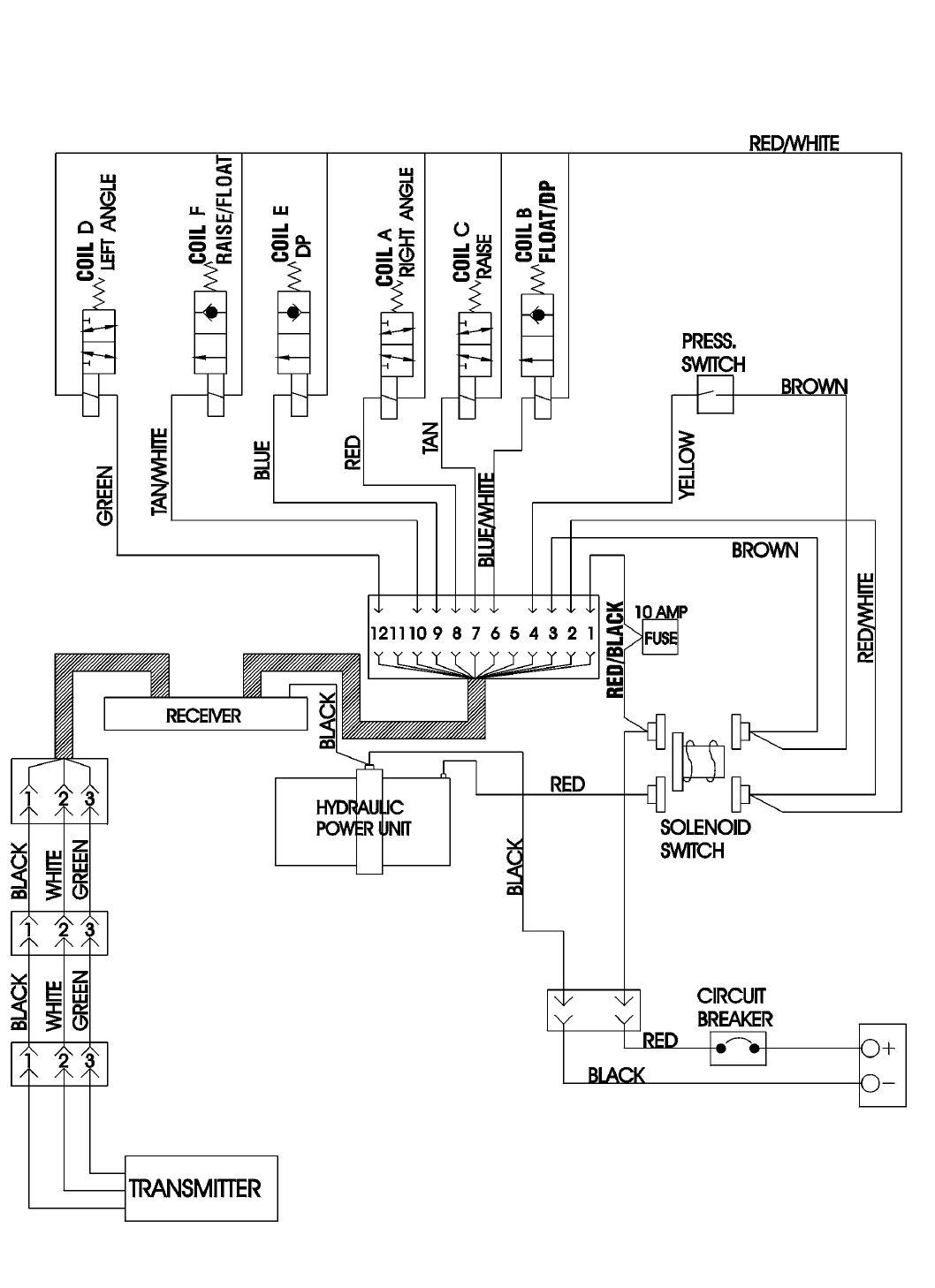
9
WIRING SCHEMATIC
(STRAIGHT BLADE - DOWN PRESSURE SYSTEM)
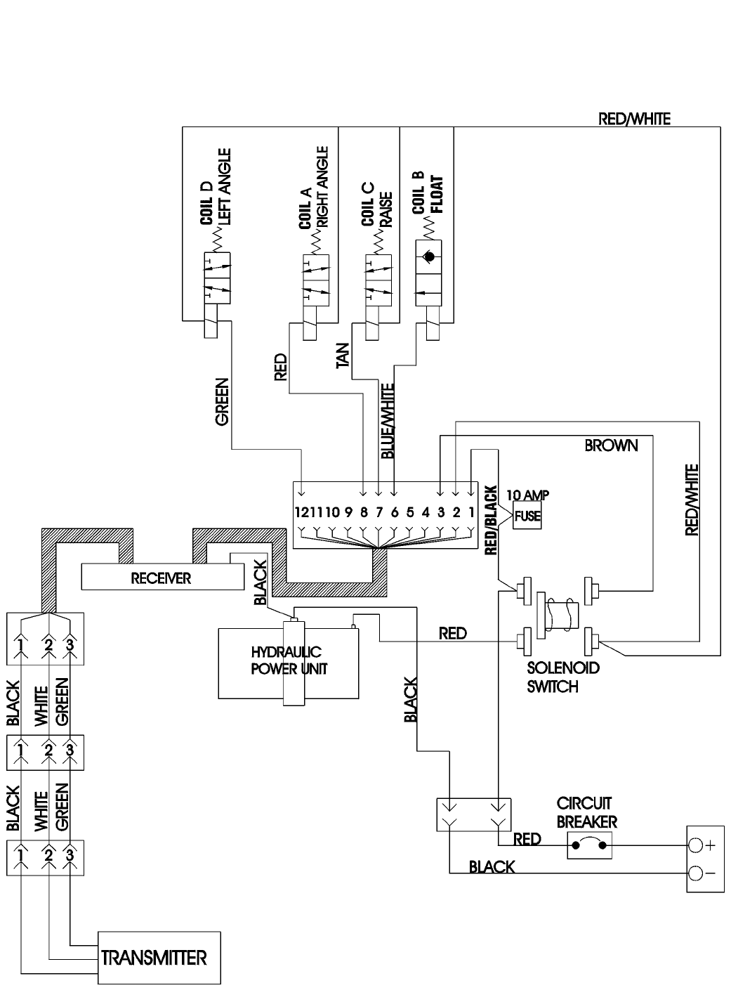
10
WIRING SCHEMATIC
(STRAIGHT BLADE - GRAVITY DOWN SYSTEM)
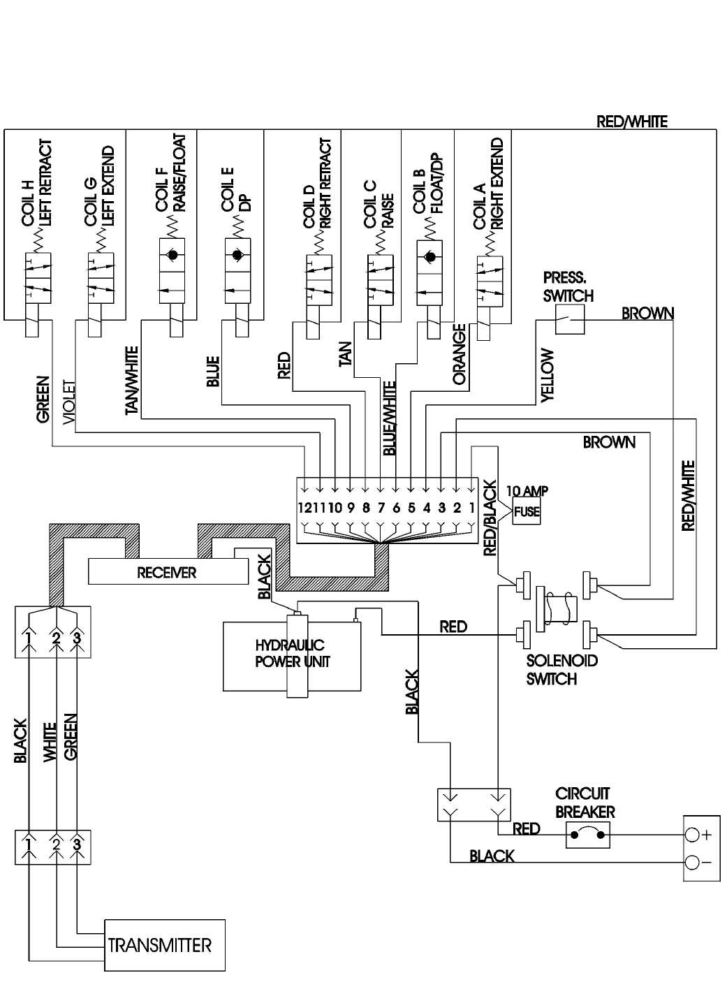
11
WIRING SCHEMATIC
(V PLOW)

SNO-WAY PLOWS - LIMITED WARRANTY
FIVE YEAR STRUCTURAL LIMITED WARRANTY COVERAGE
The Sno-Way snow plow structural elements are warranted to be free from defects in materials and workmanship for a period of five years from date of
delivery from an authorized Sno-Way Dealer. The Sno-Way Warranty Registration card for the product must be properly filled out and mailed to
Sno-Way within 30 days of date of purchase to obtain benefits of this section of warranty.
Structural elements are defined for this warranty as: Blade frames, A-frames, Swing Frames, vehicle sub frames, and structural components
(weldments) of Sno-Way snow plows.
TWO YEAR STANDARD LIMITED WARRANTY COVERAGE
The Sno-Way snow plow nonstructural components are warranted to be free from defects in workmanship for a period of two years from date of delivery
from an authorized Sno-Way Dealer. The Sno-Way Warranty Registration card for the product must be properly filled out and mailed to Sno-Way within
30 days of date of purchase to obtain the benefits of this section of warranty.
Nonstructural product components are defined for this warranty as: Blade inserts (Lexan/Hyzod or steel) and the SM01 Hydraulic power system
and control module.
ONE YEAR STANDARD LIMITED WARRANTY
ACCESORIES / SERVICE PARTS / COMPONENTS.
Sno-Way International, Inc. Warrants accessories, service parts and components purchased separately for a period of one year after original purchase
to be free from defects in material and workmanship.
DEFINITION OF PRODUCT:
Product as used throughout this warranty means the Sno-Way line of Predator snow plows, straight blades ans "V" blades and components thereof.
EXCLUSIONS UNDER THIS WARRANTY PROGRAM:
1. The installation of product must be an approved installation in accordance with the Sno-Way Vehicle Application Guide, Installation Instructions
Manual and the Owner’s Manual.
2. The "use" of the Sno-Way product must be in conformity with the operating and maintenance instructions as set forth in the Owner’s Manual.
3. Damage as a result of accident, misuse and/or negligence is not covered.
4. The polycarbonate moldboard under the two year warranty does not cover: Puncture, Hazing, Abrasion, Yellowing, Scratching or Chemical Damage.
5. Normal wear items are excluded (Without limitation): Paint finish-corrosion/contamination, Bushings and bearings, Plow shoes, Plow cutting edges,
Blade markers/pins/clips, Accessory items and non-standard attachments - or any damage caused by the addition of non-standard attachments not
sold by Sno-Way.
6. Specific exclusions relating to items covered under the Two Year Warranty: Fasteners and damage caused by failure to retighten fasteners, Electric
contact corrosion - damage or abrasion of wiring harness, Control key pads/contacts, Any damage resulting from a failure to properly service and
maintain the product as prescribed in the Owner’s Manual.
7. General exclusions:
(A) Any and all damage from the improper installation of product, misapplication of product, abusive use of vehicle and/or product, failure to properly
maintain and service, improper repair, service or alteration of product, and any damage as a result of accident or misuse.
(B) Sno-Way will not be liable for any expense not related to defects in materials and workmanship. The attachment of product to or upon a vehicle,
including any necessary modification of product or vehicle, is entirely at the purchasers risk and expense, and compliance with applicable motor vehicle
rules and regulations is the responsibility of the installer.
(C) This Warranty when applicable applies to the "first" purchaser of product installed in accordance with Sno-Way Application Guides, Installation and
Owner’s Manuals, and to the transfer of the product by the "first" purchaser to another approved vehicle application by an authorized Sno-Way Dealer.
(D) The "repair" and/or replacement of any part or component is at the option of Sno-Way.
(E) Indirect costs incurred while "product" is being repaired during the warranty period are excluded such as; lost time, equipment rental, transportation
charges, and similar incidental charges incurred.
OBTAINING WARRANTY SERVICE
To obtain warranty service, promptly return the product or any defective part at your expense to any authorized Sno-Way Dealer during the warranty
period. Replacement or repair of defective or inadequate parts shall be performed without charge for labor or materials by such Dealer at his regular
place of business during regular business hours after inspection and determination that the warranty applies.
Purchaser shall prepay all freight charges for returning Product or component to Dealer, Sno-Way or any other location designated by Sno-Way.
Note: The Sno-Way Technical Services help line is designed to service Sno-Way Dealers. Sno-Way Technical and Customer Service will help you
locate your nearest Sno-Way Dealer.
Please also use the Sno-Way web site with the Dealer locator: www.snoway.com
DISCLAIMERS:
1. Sno-Way warrants it’s Products only as set forth in this warranty. Sno-Way makes no other warranties, express or implied, and disclaims all other
warranties, including any implied warranty of merchantability or fitness for any particular purpose.
2. Sno-Way’s obligations under this warranty are limited to those expressed in this warranty, and Sno-Way shall not be liable to the purchaser or any
third party for any direct or indirect, incidental or consequential damage or loss.
3. No person is authorized to modify or add to this warranty in any manner.
4. If any Sno-Way product is improperly installed, altered, misused, damaged or otherwise tampered with, this warranty shall lapse and become null and
void.
LEGAL RIGHTS:
Some states do not allow limitations on how long an implied warranty lasts or exclusions or limitations of incidental or consequential damages, so the
above limitations or exclusions may not apply fully to you. This w arranty gives you specific legal rights, and you may also have other rights which vary
from state to state. All "other" provisions and "limitations" not altered by local law shall continue to apply.
ENFORCEMENT/CONSTRUCTION
This Warranty shall be enforced and construed under the laws of the State of Wisconsin.
SNO-WAY INTERNATIONAL, INC.
SNO-WAY® INTERNATIONAL, INC.
Hartford, WI 53027 USA
Website: www.snoway.com
©2004 Sno-Way® International