Socket Mobile BTM-2 KwikBlue Bluetooth Module User Manual HIS 2 ASIC Specification
Socket Mobile, Inc. KwikBlue Bluetooth Module HIS 2 ASIC Specification
UserManual.wiki
>
Socket Mobile
>
BTM 2 User Manual
Manual revised
Navigation menu
Upload a User Manual
Namespaces
Wiki Guide
HTML
PDF
Info
Views
User Manual
Discussion / Help
Navigation


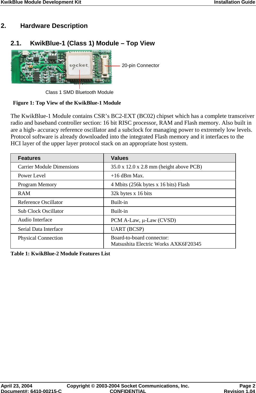
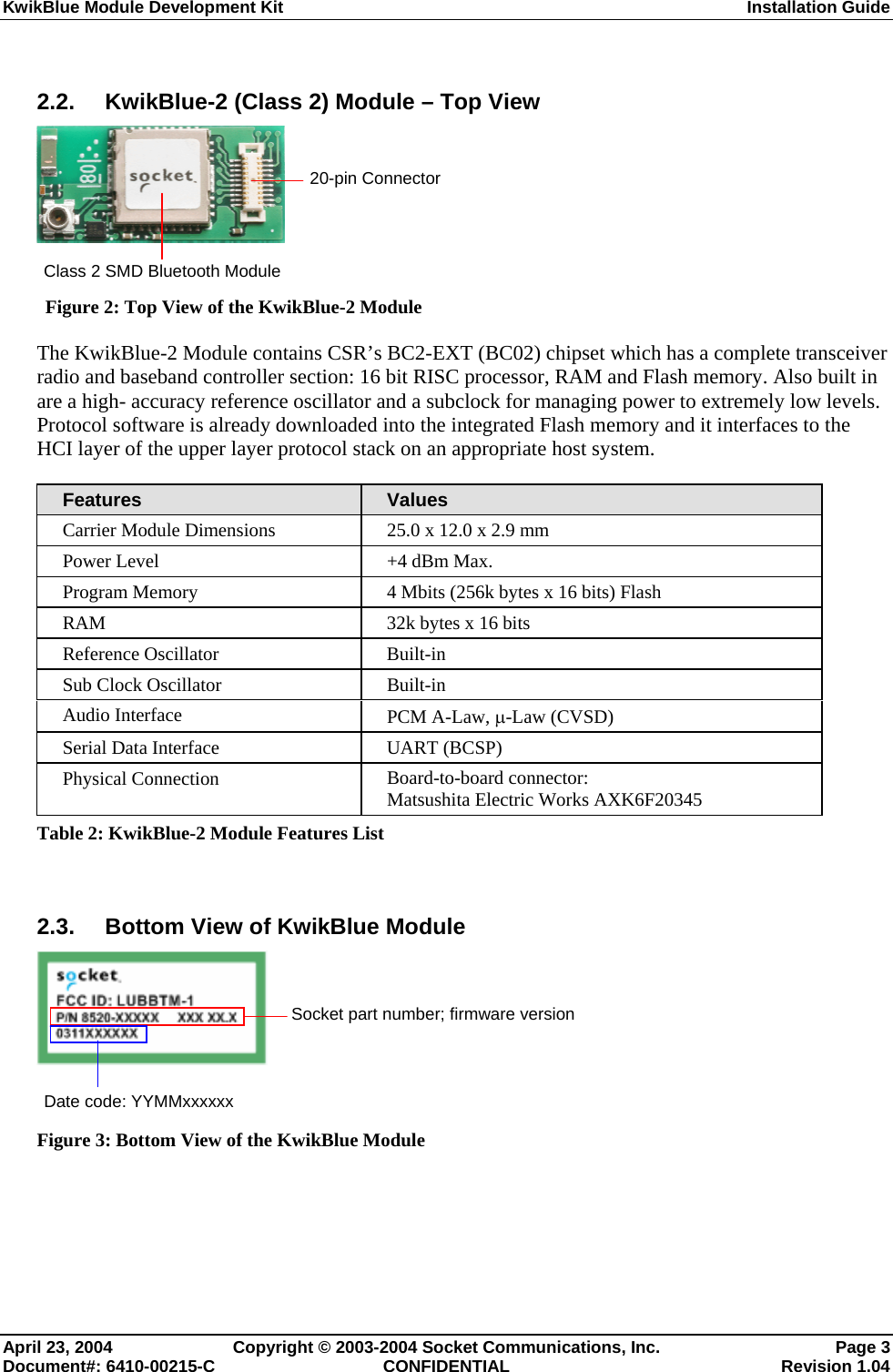
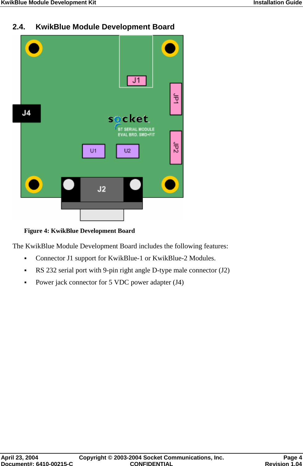
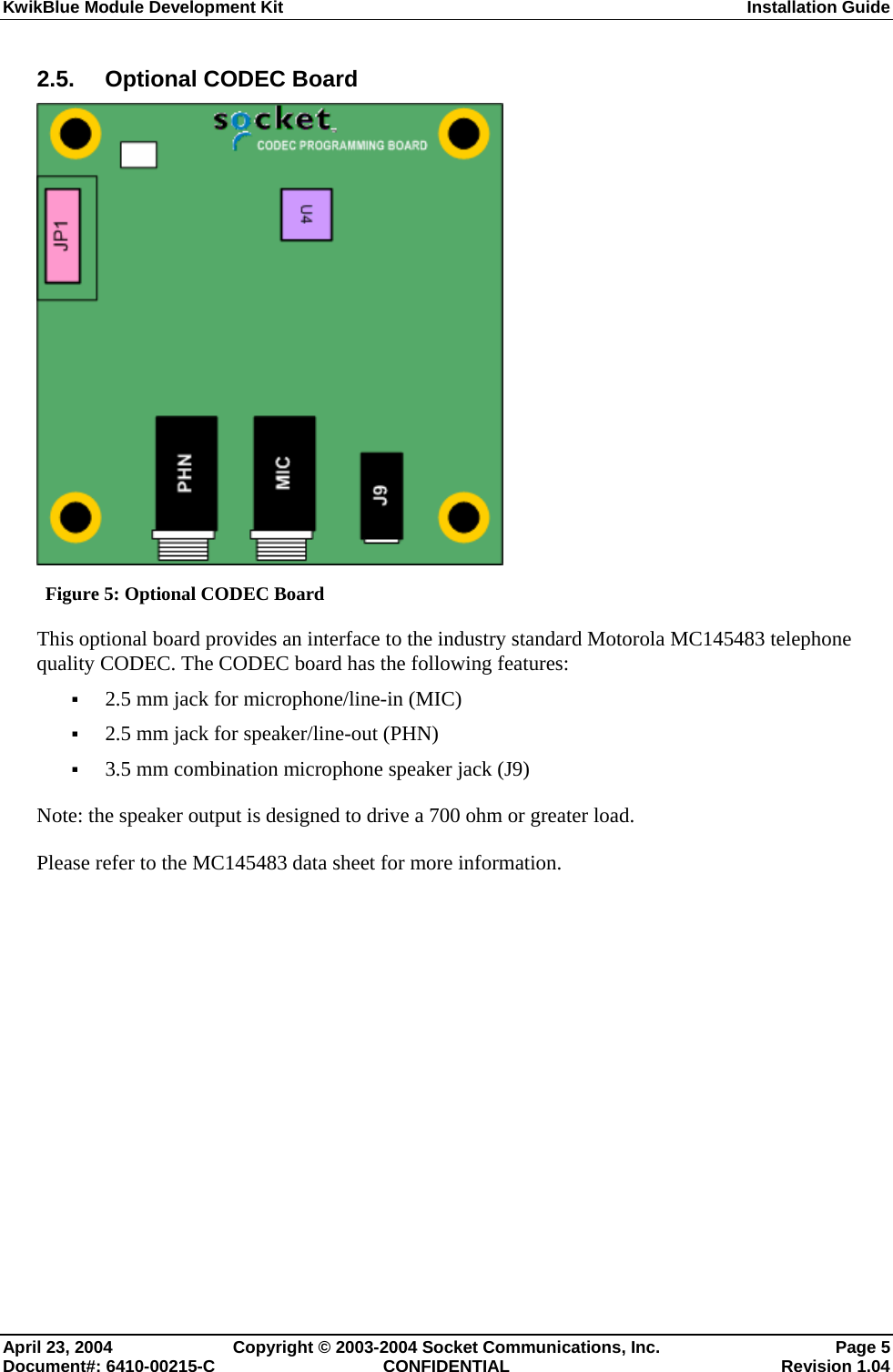
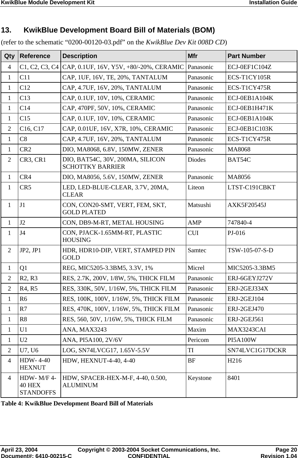
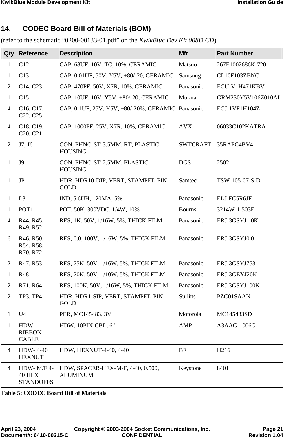
![KwikBlue Module Development Kit Installation Guide c) There is a program on the KwikBlue Dev Kit 008D CD that can be used to open a COM port on your device and verify the module is connected correctly. The program is called PrintDemo.exe and is under the “\Utilities\Print Demo” folder. i) The KwikBlue Module sends out a repeating sequence of connection bytes “C0 00 41 00 BE DA DC ED ED C0” every 250 ms. These bytes indicate to the Bluetooth drivers running on the WinCE device that the module is ready to be used. When the COM port that the module is connected to is opened, the bytes can be displayed. This indicates that the module is connected correctly and ready to be used by the Bluetooth drivers. The baud rate for opening the port is specified in Port.c and must be set: PortDCB.BaudRate = 921600; PortDCB.BaudRate = 115200; (default module baud) ii) The PrintDemo.exe has a menu selection called 'Load Stack'. This is a one line ActivateDevice() call to the registry to which loads the stack. The code is provided below for reference. The ActivateDevice() call loads BCSPStack.dll. HANDLE g_hBCSP; case IDC_LOAD_BCSP: g_hBCSP = ActivateDevice (TEXT("SOFTWARE\\Socket Communications\\Bluetooth\\Bt Device"), 0); if(g_hBCSP == NULL) { MessageBox(hDlg, TEXT("ActivateDevice (BCSP) Failed"), TEXT("Error BCSP Load"), MB_OK); } break; d) BCSPStack.dll in turn loads BtDevMan.exe. BtDevMan.exe appears as a Bluetooth icon running in the screen tray task bar. e) Virtual COM Port configurations: BtDevMan.exe loads BTVCOMM.dll. All Bluetooth COM ports that are used by the stack come from BTVCOMM.dll. Bluetooth needs at least one default COM port to function. For industrial type applications where the remote device being connected to expects to be a printer or GPS device, the default COM port is usually configured to be the "Bluetooth COM Port" (Serial Profile). For more commercial applications where the remote device is expected to be a phone, the default COM port is configured to be the "Bluetooth Phone Port" (this is the standard retail release configuration). The following registries enable a Virtual COM port for use. f) HKEY_LOCAL_MACHINE\SOFTWARE\Socket Communications\BtDevMan\1.0 [TYPE_DWORD] COMEnabled=1 (Bluetooth COM Port (Serial Profile)) [TYPE_DWORD] FaxEnabled=0 [TYPE_DWORD] DesktopEnabled=0 [TYPE_DWORD] LapEnabled=0 [TYPE_DWORD] PrinterEnabled=0 [TYPE_DWORD] PhoneEnabled=0 April 23, 2004 Copyright © 2003-2004 Socket Communications, Inc. Page 15 Document#: 6410-00215-C CONFIDENTIAL Revision 1.04](https://usermanual.wiki/Socket-Mobile/BTM-2/User-Guide-417889-Page-22.png)